EP0528830B1 - Vorrichtung zum unterscheiden von münzen - Google Patents
Vorrichtung zum unterscheiden von münzen Download PDFInfo
- Publication number
- EP0528830B1 EP0528830B1 EP91908200A EP91908200A EP0528830B1 EP 0528830 B1 EP0528830 B1 EP 0528830B1 EP 91908200 A EP91908200 A EP 91908200A EP 91908200 A EP91908200 A EP 91908200A EP 0528830 B1 EP0528830 B1 EP 0528830B1
- Authority
- EP
- European Patent Office
- Prior art keywords
- coin
- window
- width
- signals
- coins
- Prior art date
- Legal status (The legal status is an assumption and is not a legal conclusion. Google has not performed a legal analysis and makes no representation as to the accuracy of the status listed.)
- Revoked
Links
- 238000009826 distribution Methods 0.000 claims abstract description 28
- 230000001939 inductive effect Effects 0.000 claims abstract description 8
- 230000008878 coupling Effects 0.000 claims description 4
- 238000010168 coupling process Methods 0.000 claims description 4
- 238000005859 coupling reaction Methods 0.000 claims description 4
- 230000004044 response Effects 0.000 claims description 2
- 238000000034 method Methods 0.000 claims 3
- 230000006870 function Effects 0.000 description 4
- 230000008859 change Effects 0.000 description 3
- 230000008901 benefit Effects 0.000 description 1
- 238000010586 diagram Methods 0.000 description 1
- 230000003993 interaction Effects 0.000 description 1
- 238000004519 manufacturing process Methods 0.000 description 1
- 238000012544 monitoring process Methods 0.000 description 1
Images


Classifications
-
- G—PHYSICS
- G07—CHECKING-DEVICES
- G07D—HANDLING OF COINS OR VALUABLE PAPERS, e.g. TESTING, SORTING BY DENOMINATIONS, COUNTING, DISPENSING, CHANGING OR DEPOSITING
- G07D5/00—Testing specially adapted to determine the identity or genuineness of coins, e.g. for segregating coins which are unacceptable or alien to a currency
- G07D5/08—Testing the magnetic or electric properties
Definitions
- This invention relates to coin discrimination apparatus with improved discrimination between true and fraudulent coins and has particular but not exclusive application to a multi-coin validator.
- a number of sensor means in the form of a coils which are energised to produce an inductive coupling with the coin.
- the degree of interaction between the coin and the coil is a function of the relative size of the coin and coil, the material from which the coin is made and also its surface characteristics.
- data indicative of the coin under test can be provided. The data can be compared with information stored in a memory to determine coin denomination and authenticity.
- Our UK Specification 2 169 429 discloses coin discrimination apparatus utilising a plurality of inductive sensor coils which are each included in a respective resonant circuit.
- the resonant circuits are driven by a variable frequency oscillator through a multiplexer.
- the natural resonant frequency of the resonant circuit is altered due to the inductive coupling between the coin and the coil.
- the circuit is maintained at its natural resonant frequency by means of a phase locked loop which alters the frequency of the oscillator so as to track the natural resonant frequency of the resonant circuit during passage of the coin passed the coil.
- the amplitude of the oscilatory signal developed across the resonant circuit varies substantially on a transitory basis.
- the amplitude deviation produced by passage of the coin past the coil is a function of the coin denomination. It has been found that by using three coils of different sizes and configurations, three coin signals can be provided which uniquely characterise coins of a particular coin set e.g. the UK coin set.
- the amplitude deviations produced by the three coils are digitised to produce the coin signals and are then compared with reference values stored in a programmable memory in order to discriminate between coins of different denominations, and frauds.
- the data stored in the programmable memory is arranged to define windows of acceptable values for the coin signals.
- the windows are required because true coins of a particular denomination exhibit minor deviations in the values of the coin signals from coin to coin and the windows are selected so as to encompass the range of values normally expected from coins of a particular denomination.
- a coin is determined to be acceptable if the coin signals produced from the respective sensor coils each lie within the range of values defined by the windows stored in the memory.
- first and second window widths are stored for each of first and second windows associated with the coin signals from first and second of the sensor means, the first window width corresponding to the width of a distribution of coin signals associated with acceptable coins of a particular denomination, and the second window width corresponding to the width of the distribution but excluding therefrom a range of values corresponding to fraudulent coins, and a coin under test is deemed to be acceptable upon the coin signals falling within the either a first or a second acceptance condition, wherein for the first acceptance condition, the value of the first coin signal falls within the first window width of the first window, and the value of the second coin signal falls within the second window width of the second window, and for the second acceptance condition, the value of the first coin signal falls within the second window width of the first window, and the value of the second coin signal falls within the first window width of the second window.
- two independent acceptance conditions are permitted, wherein for the first condition, the range of values of coin signal corresponding to a fraudulent coin is excluded from the second window and, for the second acceptance condition, the range of coin values for fraudulent coins for the second coin signal are excluded from the width of the first window.
- a substantially improved rejection rate of fraudulent coins is achieved.
- the invention may include a third sensor means which in operation produces a coin signal within a window width which is substantially the same both for fraudulent coins and for acceptable coins of the particular denomination.
- the apparatus consists of a coin path 1 along which coins under test roll edgewise past first, second and third sensor coils C1, C2, C3. If the coin detected by the sensor coils is identified to be a true coin, a solenoid operated accept gate 2 is opened to allow the coin to pass along path la down an accept chute 3. If the coin is identified to have non-acceptable characteristics such as a fraudulent coin, the gate 2 is not opened and the coin passes along path 1b to reject chute 4.
- An accept coil C4 is provided in the accept chute 3, which is energised in such a manner as to detect the presence of acceptable coins.
- Sensor coils C1, and C3 are disposed on opposite sides of the coin path 1 and the coil C2 is arranged to wrap around the path such that its axis is parallel to the length thereof.
- the three coils are energised at different but relatively close frequencies F1, F2, F3 in the KHz range.
- the coils C1, C2, C3 are shown schematically, energised at their respective different frequencies F1, F2, F3 by means of drive circuitry 5.
- Each of the coils is connected in a respective resonant circuit and as the coin rolls passed the coil, eddy type inductive coupling occurs between the coin and the coil, so as to alter the impedence of the resonant circuit. This produces a change in frequency and/or amplitude of the signal developed in the resonant circuit and this change is a function of the coin under test.
- circuitry for frequency tracking is indicated generally by the circuit 5, which provides outputs c1, c2, c3 indicative of the amplitude developed by the coils C1, C2, C3 during passage of a coin under test, which are fed to a microprocessor 6.
- the microprocessor operates in an idle mode in the absence of a coin under test so as to determine base values c01, c02, c03, of the signals c1, c2, c3.
- the microprocessor switches to a coin sensing mode in which the values of the signals c are repetitively sampled as the coin passes the coils.
- the microprocessor can compute the peak deviations of the signals c1, c2, c3 from the respective base values c01, c02, c03 whilst the coin passes the coils.
- these peak deviation signals substantially uniquely characterise the coin under test and will be referred to herein as coin signals x1, x2, x3 for the coils C1, C2, C3 respectively.
- An EEPROM 7 contains stored values indicative of acceptable coins.
- the information is stored in terms of acceptance ranges or windows for the signals x1, x2, x3 and an individual set of windows is provided for each coin denomination. It is necessary to provide windows because the characteristics of individual coins of a particular denomination vary slightly from coin to coin. Thus, for an individual coin denomination, stored windows W1, W2, W3 are provided for comparison with the coin signals x1, x2, x3 respectively. If the coin signals x each fall within the respective windows W the microprocessor determines that the coin is of a particular denomination and energises the solenoid operated accept gate 2 such that the coin is directed to the accept chute 3 ( Figure 1).
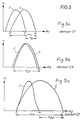
- this shows the distribution of values of the coin signals x1, x2, x3 produced for a distribution of coins of a particular denomination fed through the validator.
- the distribution of the values of the coin signals x1, x2, x3 as a function of coin number n is shown by the distribution curves referenced T.
- the windows W stored in the EEPRON 7 should have window widths W1 1, W2 1, W3 1. These window widths are substantially coextensive with the width of the distributions T of values of x1, x2, x3.
- the microprocessor 6 determines whether the respective signals from a particular coin under test x1, x2, x3 fall within the window ranges W1 1, W2 1 and W3 1. If all three conditions are satisfied the coin is accepted to be of a particular denomination corresponding to the stored window widths but otherwise is determined not to be of the particular denomination. Further sets of windows may be stored in the EEPROM corresponding to different denominations and the microprocessor may be arranged to check against all sets of windows. If the coin is found not to be of a stored denomination, it is rejected due to the fact that the microprocessor does not operate the accept gate 2 and consequently, the coin passes to the reject chute 4 ( Figure 1).
- two alternative acceptance conditions are provided. This is achieved by programming two window widths in association with the windows W1, and W2.
- the window W1 for this coil has a first window width W1 1 and a second window width W1 2. These window widths are shown schematically in Figure 3a.
- the first window width W1 1 corresponds to the width of the true coin distribution T and is stored in the EEPROM 7 as lower and upper limits a, b respectively.
- the second window width W1 2 corresponds to the range of values of x1 for which the distributions F, T do not overlap, i.e. values which are unambiguously associated with a true coin.
- the window width W1 2 is stored as lower and upper limits 1, b in the EEPROM 7.
- the second window width W1 2 corresponds to the width of the true coin distribution T but excludes the values associated with the false coin.
- the senor C2 has an associated second window W2 with first and second window widths W2 1, W2 2.
- the first window width W2 1 corresponds to the entire width of the true coin distribution T and is held in EEPROM 7 as lower and upper limits e, f.
- the second window width W2 2 corresponds to the width of the distribution T but excludes therefrom values associated with the false coin distribution F and is stored as lower and upper limit values m, f in the EEPROM 7.
- the characteristic of the sensor coil 3 is such that the true and false coin distributions F, T are substantially similar for the coin signal x3 and consequently, the window W3 is stored with only one window width defined by lower and upper limits c, d corresponding to the width of the true coin distribution.
- the microprocessor tests for a first acceptance condition for a particular set of coin signals x1, x2, x3 as follows: a ⁇ x1 ⁇ b; m ⁇ x2 ⁇ f; c ⁇ x3 ⁇ d
- the microprocessor 6 determines whether the coin signals satisfy a second acceptance condition as follows: 1 ⁇ x1 ⁇ b; e ⁇ x2 ⁇ f; c ⁇ x3 ⁇ d
- condition (2) If the coin signals satisfy condition (2) the coin is accepted as being of the particular denomination; otherwise the coin is determined not to be of the particular denomination.
- the microprocessor may then run through similar tests for different windows corresponding to different coin denominations.
- the various window widths W1 1, W1 2, W2 1, W2 2, W3 can be programmed into the EEPROM, typically, but not necessarily during manufacture of the validator.
- the window widths may be determined during a setup phase during which a number of true coins and false coins are passed through a validator to determine the distribution F and T discussed in relation to Figure 3.
- the advantage of providing the first and second acceptance conditions (1, 2) is that a substantially improved discrimination between true coins and fraudulent coins of similar characteristics is provided.
- the first and second acceptance conditions (1, 2) are so arranged that each includes a window width W1 2, W2 2 which corresponds to a range of values of coin signal unambiguously associated with a true coin.
- the other two requirements of each acceptance condition provide an indication that the coin generally corresponds to the expected distribution T for the particular coin signal. In this way substantially improved coin discrimination between true and fraudulent coins is achieved.
- coin signals x are digitised amplitude deviations, it will be appreciated that they can be produced in other ways e.g. in terms of a frequency deviation. Also, sensors other than inductive coil sensors could be utilised.
Landscapes
- Physics & Mathematics (AREA)
- General Physics & Mathematics (AREA)
- Testing Of Coins (AREA)
- Control Of Vending Devices And Auxiliary Devices For Vending Devices (AREA)
- Noodles (AREA)
Claims (10)
- Münzunterscheidungsvorrichtung, die folgendes aufweist:
eine Einrichtung, die einen Weg (1) definiert, auf dem sich Münzen entlangbewegen, die gerade geprüft werden,
eine erste und eine zweite Sensoreinrichtung (C1, C2), um eine Münze abzutasten, während sie sich auf dem Weg entlangbewegt,
eine Einrichtung (5), die auf die Sensoreinrichtung anspricht, um jeweils für die erste und die zweite Sensoreinrichtung erste und zweite Münzsignale (x₁, x₂) zu erzeugen, wobei die Münzsignalwerte von der Münze abhängen, die gerade geprüft wird,
eine Speichereinrichtung (7), die Daten speichert, um erste und zweite Fenster (W₁, W₂) zu definieren, die jeweils eine Breite für akzeptable Münzsignalwerte aufweisen, und
eine Einrichtung (6), um die Münzsignale mit Daten zu vergleichen, die im Speicher gespeichert sind, um festzustellen, ob die Münzsignale in den Fensterbereich fallen,
dadurch gekennzeichnet, daß
die Daten für die ersten und zweiten Fenster (W₁, W₂) jeweils gespeichert werden, um sowohl eine erste als auch eine zweite Fensterbreite (W₁₁, W₁₂; W₂₁, W₂₂) vorzusehen, wobei die erste Fensterbreite der Breite einer Verteilung von Münzsignalen entspricht, die akzeptablen Münzen eines bestimmten Münzwerts zugeordnet sind, und wobei die zweite Fensterbreite der Breite der Verteilung entspricht, jedoch unter Ausschluß eines Wertebereichs, der Falschmünzen entspricht, und dadurch, daß
eine Münze, die gerade geprüft wird, als akzeptabel angesehen wird, wenn die Münzsignale entweder in eine erste oder in eine zweite Annahmebedingung fallen, wobei
im Fall der ersten Annahmebedingung der Wert des ersten Münzsignals in den Bereich der ersten Fensterbreite des ersten Fensters (W₁₁) und der Wert des zweiten Münzsignals in den Bereich der zweiten Fensterbreite des zweiten Fensters (W₂₂) fällt, und wobei
im Fall der zweiten Annahmebedingung der Wert des ersten Münzsignals in den Bereich der zweiten Fensterbreite des ersten Fensters (W₁₂) und der Wert des zweiten Münzsignals in den Bereich der ersten Fensterbreite des zweiten Fensters (W₂₁) fällt. - Vorrichtung nach Anspruch 1, die eine dritte Sensoreinrichtung (C3) aufweist, um festzustellen, daß sich eine Münze auf dem Weg entlangbewegt, um ein drittes Münzsignal (x₃) zu erzeugen, wobei die Speichereinrichtung Daten speichert, um ein drittes Fenster (W₃) von einer Breite zu definieren, die der Breite einer Verteilung von Münzsignalen entspricht, die akzeptablen Münzen mit dem bestimmten Münzwert zugeordnet sind, und bei der die erste und die zweite Annahmebedingung fordern, daß das dritte Münzsignal im Bereich der Breite des dritten Fensters liegt.
- Vorrichtung nach Anspruch 1 oder 2, bei der die Speichereinrichtung (7) Daten aufweist, um eine Mehrzahl von Fenstersätzen zu definieren, die Münzen von unterschiedlichem Münzwert entsprechen.
- Vorrichtung nach einem der vorhergehenden Ansprüche, bei der die Speichereinrichtung (7) einen EEPROM umfaßt.
- Vorrichtung nach einem der vorhergehenden Ansprüche, bei der die Vergleichseinrichtung (6) einen Mikroprozessor umfaßt.
- Vorrichtung nach einem der vorhergehenden Ansprüche, bei der die Sensoreinrichtung (C) eine Mehrzahl von induktiven Sensorspulen aufweist, die angeordnet sind,um jeweils unterschiedliche induktive Kopplungen mit einer Münze zu erzeugen, die gerade geprüft wird.
- Münzunterscheidungsvorrichtung nach einem der vorhergehenden Ansprüche, die ein Annahmegate (2) aufweist, das so betrieben wird, daß es in Antwort auf die erste oder die zweite Annahmebedingung eine Münze akzeptiert.
- Verfahren zur Münzunterscheidung, das die folgenden Schritte aufweist:
Durchführen eines ersten und eines zweiten Tests an einer Münze, um in Abhängigkeit von der Münze, die gerade getestet wird, erste und zweite Münzsignale (x₁, x₂) zu erzeugen und
Vergleichen der Münzsignale mit Fenstern (W₁, W₂), die jeweils eine Breite für akzeptable Werte der Münzsignale aufweisen,
dadurch gekennzeichnet, daß
die Daten für das erste und das zweite Fenster (W₁, W₂) jeweils gespeichert werden, um sowohl eine erste als auch eine zweite Fensterbreite (W₁₁, W₁₂; W₂₁, W₂₂) vorzusehen, wobei die erste Fensterbreite der Breite einer Verteilung von Münzsignalen entspricht, die akzeptablen Münzen eines bestimmten Münzwerts zugeordnet sind, und wobei die zweite Fensterbreite der Breite der Verteilung entspricht, jedoch unter Ausschluß eines Wertebereichs, der Falschmünzen entspricht, und dadurch, daß
eine Münze, die gerade geprüft wird, als akzeptabel angesehen wird, wenn die Münzsignale entweder unter eine erste oder unter eine zweite Annahmebedingung fallen, wobei
im Fall der ersten Annahmebedingung der Wert des ersten Münzsignals in den Bereich der ersten Fensterbreite des ersten Fensters (W₁₁) und der Wert des zweiten Münzsignals in den Bereich der zweiten Fensterbreite des zweiten Fensters (W₂₂) fällt, und wobei
im Fall der zweiten Annahmebedingung der Wert des ersten Münzsignals in den Bereich der zweiten Fensterbreite des ersten Fensters (W₁₂) und der Wert des zweiten Münzsignals in den Bereich der ersten Fensterbreite des zweiten Fensters (W₂₁) fällt. - Verfahren nach Anspruch 8, das die Durchführung eines dritten Tests an der Münze zur Erzeugung eines dritten Münzsignals (x₃) und den Vergleich des dritten Münzsignals mit einem dritten Fenster (W₃) beinhaltet, und bei dem die erste und die zweite Annahmebedingung fordern, daß das dritte Münzsignal im Bereich der Breite des dritten Fensters liegt.
- Verfahren nach Anspruch 8 oder 9, das den Vergleich der Münzsignale mit einer Mehrzahl von Fenstersätzen beinhaltet, die Münzen mit unterschiedlichen Münzwerten entsprechen.
Applications Claiming Priority (3)
| Application Number | Priority Date | Filing Date | Title |
|---|---|---|---|
| GB9010766 | 1990-05-14 | ||
| GB909010766A GB9010766D0 (en) | 1990-05-14 | 1990-05-14 | Coin discrimination apparatus |
| PCT/GB1991/000685 WO1991018372A1 (en) | 1990-05-14 | 1991-04-30 | Coin discrimination apparatus |
Publications (2)
| Publication Number | Publication Date |
|---|---|
| EP0528830A1 EP0528830A1 (de) | 1993-03-03 |
| EP0528830B1 true EP0528830B1 (de) | 1995-04-26 |
Family
ID=10675958
Family Applications (1)
| Application Number | Title | Priority Date | Filing Date |
|---|---|---|---|
| EP91908200A Revoked EP0528830B1 (de) | 1990-05-14 | 1991-04-30 | Vorrichtung zum unterscheiden von münzen |
Country Status (8)
| Country | Link |
|---|---|
| US (1) | US5379876A (de) |
| EP (1) | EP0528830B1 (de) |
| JP (1) | JPH05508491A (de) |
| AU (1) | AU648557B2 (de) |
| DE (1) | DE69109287T2 (de) |
| ES (1) | ES2073749T3 (de) |
| GB (1) | GB9010766D0 (de) |
| WO (1) | WO1991018372A1 (de) |
Families Citing this family (24)
| Publication number | Priority date | Publication date | Assignee | Title |
|---|---|---|---|---|
| JP3002904B2 (ja) * | 1991-04-16 | 2000-01-24 | 株式会社日本コンラックス | 硬貨処理装置 |
| DE4121034C1 (de) * | 1991-06-26 | 1992-09-10 | National Rejectors Inc. Gmbh, 2150 Buxtehude, De | |
| ES2046119B1 (es) * | 1992-06-01 | 1994-10-16 | Azkoyen Ind Sa | Procedimiento para la verificacion de monedas. |
| JP2948035B2 (ja) * | 1992-11-11 | 1999-09-13 | 株式会社日本コンラックス | コインの判別方法および判別装置 |
| ES2066698B1 (es) * | 1992-12-29 | 1995-08-16 | Azkoyen Ind Sa | Nuevo sistema de programacion de selectores de moneda. |
| GB9419912D0 (en) * | 1994-10-03 | 1994-11-16 | Coin Controls | Optical coin sensing station |
| GB9507257D0 (en) * | 1995-04-07 | 1995-05-31 | Coin Controls | Coin validation apparatus and method |
| DE19524963A1 (de) * | 1995-07-08 | 1997-01-09 | Bosch Gmbh Robert | Schaltnetzteil mit B-Steuerung |
| CA2226617A1 (en) | 1995-07-14 | 1997-02-06 | Coin Controls Ltd. | Coin validator |
| GB9601335D0 (en) | 1996-01-23 | 1996-03-27 | Coin Controls | Coin validator |
| GB9611659D0 (en) | 1996-06-05 | 1996-08-07 | Coin Controls | Coin validator calibration |
| ES2175441T3 (es) | 1996-07-29 | 2002-11-16 | Qvex Inc | Procedimiento y aparato de validacion de monedas. |
| GB2326964B (en) | 1998-03-23 | 1999-06-16 | Coin Controls | Coin changer |
| US6053299A (en) * | 1999-04-15 | 2000-04-25 | Money Controls, Inc. | Apparatus and method for processing coins in a host machine |
| US7635059B1 (en) | 2000-02-02 | 2009-12-22 | Imonex Services, Inc. | Apparatus and method for rejecting jammed coins |
| WO2002067209A2 (en) | 2001-02-20 | 2002-08-29 | Cubic Corporation | Inductive coin sensor with position correction |
| WO2003049044A2 (en) * | 2001-12-05 | 2003-06-12 | Coinstar, Inc. | Methods and systems for detecting coin fraud in coin-counting machines and other devices |
| CN1795470A (zh) * | 2003-05-22 | 2006-06-28 | 日本功勒克斯股份有限公司 | 货币金属处理装置及其控制方法 |
| US7381126B2 (en) * | 2003-11-03 | 2008-06-03 | Coin Acceptors, Inc. | Coin payout device |
| US20050224313A1 (en) * | 2004-01-26 | 2005-10-13 | Cubic Corporation | Robust noncontact media processor |
| US9036890B2 (en) | 2012-06-05 | 2015-05-19 | Outerwall Inc. | Optical coin discrimination systems and methods for use with consumer-operated kiosks and the like |
| CN103713169B (zh) * | 2013-12-23 | 2016-09-21 | 上海金陵智能电表有限公司 | 一种感应式电能表 |
| US9443367B2 (en) | 2014-01-17 | 2016-09-13 | Outerwall Inc. | Digital image coin discrimination for use with consumer-operated kiosks and the like |
| JP6277350B2 (ja) * | 2014-12-16 | 2018-02-14 | 旭精工株式会社 | 硬貨識別装置 |
Family Cites Families (3)
| Publication number | Priority date | Publication date | Assignee | Title |
|---|---|---|---|---|
| GB8500220D0 (en) * | 1985-01-04 | 1985-02-13 | Coin Controls | Discriminating between metallic articles |
| US4845994A (en) * | 1988-02-29 | 1989-07-11 | Automatic Toll Systems, Inc. | Coin testing apparatus |
| IT1232019B (it) * | 1989-02-23 | 1992-01-23 | Urmet Spa | Perfezionamento ai selezionatori di monete |
-
1990
- 1990-05-14 GB GB909010766A patent/GB9010766D0/en active Pending
-
1991
- 1991-04-30 DE DE69109287T patent/DE69109287T2/de not_active Revoked
- 1991-04-30 EP EP91908200A patent/EP0528830B1/de not_active Revoked
- 1991-04-30 US US07/949,241 patent/US5379876A/en not_active Expired - Fee Related
- 1991-04-30 AU AU77657/91A patent/AU648557B2/en not_active Ceased
- 1991-04-30 WO PCT/GB1991/000685 patent/WO1991018372A1/en not_active Ceased
- 1991-04-30 JP JP3508242A patent/JPH05508491A/ja active Pending
- 1991-04-30 ES ES91908200T patent/ES2073749T3/es not_active Expired - Lifetime
Also Published As
| Publication number | Publication date |
|---|---|
| GB9010766D0 (en) | 1990-07-04 |
| JPH05508491A (ja) | 1993-11-25 |
| ES2073749T3 (es) | 1995-08-16 |
| AU7765791A (en) | 1991-12-10 |
| WO1991018372A1 (en) | 1991-11-28 |
| US5379876A (en) | 1995-01-10 |
| EP0528830A1 (de) | 1993-03-03 |
| AU648557B2 (en) | 1994-04-28 |
| DE69109287D1 (de) | 1995-06-01 |
| DE69109287T2 (de) | 1996-01-04 |
Similar Documents
| Publication | Publication Date | Title |
|---|---|---|
| EP0528830B1 (de) | Vorrichtung zum unterscheiden von münzen | |
| EP0399694B1 (de) | Münzprüfvorrichtung mit Kompensation der äusseren Umgebungsbedingungen | |
| US4936435A (en) | Coin validating apparatus and method | |
| US3373856A (en) | Method and apparatus for coin selection | |
| US3952851A (en) | Coin selection method and apparatus | |
| EP0708420B1 (de) | Verfahren und Vorrichtung zur Echtheitsprüfung von Geld | |
| US3918563A (en) | Coin arrival sensor | |
| US3796295A (en) | Electronic metal coin analyser | |
| JPS5927383A (ja) | 学習式硬貨等の選別装置 | |
| JPS59111587A (ja) | 硬貨処理機の検銭装置 | |
| JP4528445B2 (ja) | 貨幣類受入器 | |
| EP0904580B1 (de) | Kalibrierung eines münzprüfers | |
| EP1388822A1 (de) | Geldannahmevorrichtung | |
| AU744618B2 (en) | Coin acceptor | |
| EP1581913B1 (de) | Verbessertes geldannahmegerät | |
| US7549525B2 (en) | Money item acceptor with enhanced security | |
| EP1123537B1 (de) | Verfahren und vorrichtung zum prüfen von bimetallischen münzen | |
| JPS6063691A (ja) | 硬貨判別装置 | |
| JPS59157783A (ja) | 硬貨の選別装置 |
Legal Events
| Date | Code | Title | Description |
|---|---|---|---|
| PUAI | Public reference made under article 153(3) epc to a published international application that has entered the european phase |
Free format text: ORIGINAL CODE: 0009012 |
|
| 17P | Request for examination filed |
Effective date: 19921105 |
|
| AK | Designated contracting states |
Kind code of ref document: A1 Designated state(s): BE CH DE ES FR GB IT LI NL |
|
| 17Q | First examination report despatched |
Effective date: 19940711 |
|
| GRAA | (expected) grant |
Free format text: ORIGINAL CODE: 0009210 |
|
| AK | Designated contracting states |
Kind code of ref document: B1 Designated state(s): BE CH DE ES FR GB IT LI NL |
|
| ITF | It: translation for a ep patent filed | ||
| PG25 | Lapsed in a contracting state [announced via postgrant information from national office to epo] |
Ref country code: LI Effective date: 19950426 Ref country code: CH Effective date: 19950426 |
|
| REF | Corresponds to: |
Ref document number: 69109287 Country of ref document: DE Date of ref document: 19950601 |
|
| ET | Fr: translation filed | ||
| REG | Reference to a national code |
Ref country code: CH Ref legal event code: PL |
|
| REG | Reference to a national code |
Ref country code: ES Ref legal event code: FG2A Ref document number: 2073749 Country of ref document: ES Kind code of ref document: T3 |
|
| PLBI | Opposition filed |
Free format text: ORIGINAL CODE: 0009260 |
|
| 26 | Opposition filed |
Opponent name: MARS INCORPORATED Effective date: 19950928 |
|
| NLR1 | Nl: opposition has been filed with the epo |
Opponent name: MARS INCORPORATED |
|
| PLBF | Reply of patent proprietor to notice(s) of opposition |
Free format text: ORIGINAL CODE: EPIDOS OBSO |
|
| PLBF | Reply of patent proprietor to notice(s) of opposition |
Free format text: ORIGINAL CODE: EPIDOS OBSO |
|
| PGFP | Annual fee paid to national office [announced via postgrant information from national office to epo] |
Ref country code: ES Payment date: 19970411 Year of fee payment: 7 |
|
| RDAH | Patent revoked |
Free format text: ORIGINAL CODE: EPIDOS REVO |
|
| PGFP | Annual fee paid to national office [announced via postgrant information from national office to epo] |
Ref country code: FR Payment date: 19980410 Year of fee payment: 8 |
|
| PGFP | Annual fee paid to national office [announced via postgrant information from national office to epo] |
Ref country code: GB Payment date: 19980416 Year of fee payment: 8 |
|
| PGFP | Annual fee paid to national office [announced via postgrant information from national office to epo] |
Ref country code: BE Payment date: 19980421 Year of fee payment: 8 |
|
| PGFP | Annual fee paid to national office [announced via postgrant information from national office to epo] |
Ref country code: DE Payment date: 19980429 Year of fee payment: 8 |
|
| PGFP | Annual fee paid to national office [announced via postgrant information from national office to epo] |
Ref country code: NL Payment date: 19980430 Year of fee payment: 8 |
|
| RDAG | Patent revoked |
Free format text: ORIGINAL CODE: 0009271 |
|
| STAA | Information on the status of an ep patent application or granted ep patent |
Free format text: STATUS: PATENT REVOKED |
|
| 27W | Patent revoked |
Effective date: 19980222 |
|
| GBPR | Gb: patent revoked under art. 102 of the ep convention designating the uk as contracting state |
Free format text: 980222 |
|
| NLR2 | Nl: decision of opposition |