EP0528656A1 - Liquid heating vessels - Google Patents
Liquid heating vessels Download PDFInfo
- Publication number
- EP0528656A1 EP0528656A1 EP92307446A EP92307446A EP0528656A1 EP 0528656 A1 EP0528656 A1 EP 0528656A1 EP 92307446 A EP92307446 A EP 92307446A EP 92307446 A EP92307446 A EP 92307446A EP 0528656 A1 EP0528656 A1 EP 0528656A1
- Authority
- EP
- European Patent Office
- Prior art keywords
- liquid
- control
- thermally
- vessel
- boiling
- Prior art date
- Legal status (The legal status is an assumption and is not a legal conclusion. Google has not performed a legal analysis and makes no representation as to the accuracy of the status listed.)
- Granted
Links
Images


Classifications
-
- A—HUMAN NECESSITIES
- A47—FURNITURE; DOMESTIC ARTICLES OR APPLIANCES; COFFEE MILLS; SPICE MILLS; SUCTION CLEANERS IN GENERAL
- A47J—KITCHEN EQUIPMENT; COFFEE MILLS; SPICE MILLS; APPARATUS FOR MAKING BEVERAGES
- A47J27/00—Cooking-vessels
- A47J27/21—Water-boiling vessels, e.g. kettles
- A47J27/21008—Water-boiling vessels, e.g. kettles electrically heated
- A47J27/21058—Control devices to avoid overheating, i.e. "dry" boiling, or to detect boiling of the water
-
- H—ELECTRICITY
- H01—ELECTRIC ELEMENTS
- H01H—ELECTRIC SWITCHES; RELAYS; SELECTORS; EMERGENCY PROTECTIVE DEVICES
- H01H37/00—Thermally-actuated switches
- H01H37/02—Details
- H01H37/12—Means for adjustment of "on" or "off" operating temperature
- H01H37/16—Means for adjustment of "on" or "off" operating temperature by varying the proportion of input heat received by the thermal element, e.g. by displacement of a shield
-
- H—ELECTRICITY
- H01—ELECTRIC ELEMENTS
- H01H—ELECTRIC SWITCHES; RELAYS; SELECTORS; EMERGENCY PROTECTIVE DEVICES
- H01H37/00—Thermally-actuated switches
- H01H37/02—Details
- H01H37/12—Means for adjustment of "on" or "off" operating temperature
- H01H37/22—Means for adjustment of "on" or "off" operating temperature by adjustment of a member transmitting motion from the thermal element to contacts or latch
Definitions
- the present invention relates to liquid heating vessels which are required to heat a liquid to its boiling point and also to a lower temperature. It is particularly, but not exclusively, applicable to electric water heating vessels such as kettles and jugs which are used in making hot beverages such as tea and coffee.
- boiling water should be used for making tea
- water used in making coffee should ideally be somewhat below boiling, for example at 80°C to 90°C. Accordingly, it is common when making a coffee beverage to allow a boiled kettle or jug to stand for some time before pouring it on to the coffee. Alternatively, cold water can be added to the boiled water in the kettle or jug prior to pouring to reduce it to approximately the correct temperature. Both of these approaches are clearly inconvenient for the user, and whether or not the desired temperature is achieved can be a hit or miss affair.
- thermostats in some vessels (though typically not household jugs or kettles) to control water temperature at different predetermined temperatures.
- such thermostats can be relatively costly, and are inherently unsuited for use where one of the predetermined temperatures is intended to be the boiling point of the liquid since the boiling point varies depending on atmospheric pressure and altitude and on the hardness of the water, for example.
- liquid heating apparatus comprising a liquid heating vessel having an electric heater, a manually resettable boiling control comprising an actuator exposed to steam or vapour resulting from liquid within the container boiling and coupled to an electrical switch means for interrupting the power supply to said heater when the liquid in said vessel boils, a thermally-sensitive control including an actuator arranged or arrangeable in thermal contact with liquid within said vessel and operable to interrupt the power supply to said heater at a predetermined liquid temperature which is below the boiling point, and means for selectively rendering the thermally-sensitive control inoperable or operable so that the vessel may be adapted to provide liquid at or below its boiling point as desired.
- controls are provided for boiling a liquid, for example water, and for heating the liquid to a predetermined lower temperature.
- the thermally-sensitive control When it is desired to boil liquid in the vessel, which may be a hot water jug or kettle, the thermally-sensitive control is rendered inoperative, and the heater will be disconnected by the manually resettable boiling control in the manner of a traditional electric kettle or jug.
- the thermally-responsive control is rendered operative so that the heater will be disabled by that control at the desired lower temperature.
- Vapour activated boiling controls are well known in the art, and are already used on large numbers of jugs and kettles.
- Such controls may comprise a bimetallic actuator upon which vapour or steam produced by the liquid boiling in the vessel impinges.
- the actuator is heated by the vapour condensing thereon, and when its temperature has risen sufficiently, it will operate to trip an over-centre lever which in turn cooperates with and opens a set of switch contacts in the power supply to the heater.
- Such controls are shown, for example, in our earlier UK Patent Applications GB 2221795, GB2215134, and UK Patent 1470367.
- the thermally-sensitive control may be of any construction which when operable will provide disconnection of the power supply to the heater when the liquid is at the desired temperature.
- control may be such that once it operates, it must be positively reset by a user to reconnect the power supply to the heater, in one embodiment the control resets automatically when the sensed temperature falls below a given value whereby the control will cycle to maintain the liquid in the vessel at approximately the desired predetermined temperature.
- the thermally-sensitive control may be variable so that it may be set to operate at a variable desired liquid temperature. This may be useful if, for example, it is desired to produce white coffee with cold milk or cream which ideally requires non-boiling liquid of a somewhat higher temperature than black coffee, for example.
- the means for rendering the thermally-sensitive control inoperative may vary.
- it may comprise an electrical switch means for effectively bypassing the control.
- a further suitable means is adapted thermally to isolate the actuator of the control from liquid in the vessel, for example by interposing an insulating member between the actuator and the liquid, or by distancing the actuator from the liquid. In this way, although still connected electrically in the power supply to the heater the control will not operate to disconnect the heater before the boiling control operates.
- a mechanical link between the actuator of the thermally-sensitive control and its electrical switch means may selectively be rendered ineffective.
- the actuators of the boiling and thermally-sensitive controls may be located in any suitable position, and the controls may both be mounted to the vessel.
- the actuator of the thermally-sensitive control when operable, may be located in the liquid, or may be in thermal contact therewith eg. via a base or side wall of the vessel. In the case of a plastic vessel, thermal contact between the liquid and the actuator may be improved by including a thinner vessel wall portion, or a metal insert therein, in the vicinity of the actuator.
- the invention may also be readily embodied in so-called "cordless" electrical jugs or kettles wherein the heating vessel, rather than having a power lead directly connected to it, is removably locatable on a base unit to which the power supply is connected, and has an electrical connector for engagement with a corresponding connector on the base unit, to supply power to the heater.
- the boiling control is provided on the vessel itself while the thermally-sensitive control is provided in the base unit.
- the thermally-sensitive control comprises an actuator mounted in an upper part of the base unit so that when the vessel is placed thereon, with the control in its operable condition, the actuator is placed in thermal contact with the base wall of the heating vessel to be responsive to the temperature of the liquid therethrough.
- the actuator may be mounted in the base unit so as to be movable towards and away from the base of the heating vessel, such that when boiling liquid is required the actuator is sufficiently thermally isolated from the base of the heating vessel so that it will not operate before the liquid temperature in the vessel reaches its boiling point.
- the actuator may be moved by a cam connected to an operating lever provided on the base.
- An intermediate position or positions of the actuator may be provided whereby liquid may be heated to more than one predetermined temperatures below the boiling point e.g. for making black or white coffee as discussed above.
- the actuator is mounted within an upward projection in the base unit, and in its raised position directly engages a metal plate at the top of such projection which in turn directly engages the underside of the vessel in use.
- a preferred thermally-sensitive control may be adapted to heat the water to around 80 to 85°C for black coffee, and to around 90°C for white coffee.
- the form of the thermally-sensitive control may vary.
- An electronic control could be used incorporating an actuator in the form of a thermocouple, for example.
- this control also comprises a bimetallic actuator, which at a certain nominal operating temperature displaces, preferably by snap action, to open a set of switch contacts of the control to interrupt the power supply to the heater.
- Controls of this general type are well known. Since the temperature of the bimetallic actuator will lag somewhat behind the actual temperature of the liquid in the vessel, the operating temperature of the bimetal will typically be somewhat below the desired predetermined temperature of the liquid depending on the degree of thermal contact between the liquid and the actuator.
- the bimetallic actuator is preferably arranged to cycle so that the switch contacts open and close and the heater operates intermittently to maintain the liquid at about the predetermined temperature if the vessel is left unattended.
- the actuator of the thermally-sensitive control which in this system preferably is mounted in thermal contact with a side wall of the container, is coupled mechanically to an over-centre lever forming part of the boiling control, whereby in its operable condition the actuator of the thermally-sensitive control is adapted to trip the lever and disable the heater in the same manner as the boiling control.
- the thermally-sensitive control as defined herein shows certain components with the boiling control i.e. the over-centre lever and the associated switch contacts.
- Such system may include a mechanical link between the actuator and the over-centre lever which can be disengaged therefrom by suitable means for making tea, whereupon the over-centre lever will be tripped by the steam sensitive actuator in the normal way upon boiling.
- the actuator of the thermally-sensitive control is coupled to the over-centre lever by means of a lever member which is selectively pivotable about an axis.
- a pivot surface which is selectively engageable with and disengageable from a pivot provided on the lever is provided on a control member.
- the control member is preferably mounted on a support member so as to be slidably movable between the engaged and disengaged positions, and may extend through a suitable slot in a housing of the kettle or jug for operation by a user.
- the support member, lever and actuator are mountable as a unit to the boiling control. This allows a thermally-sensitive control to be added to a standard boiling control which may form part of an integrated control unit comprising also primary overheat and back-up protectors, as is well known in the art.
- the invention also extends to a combined boiling and thermally-sensitive control for a liquid heading vessel having an electric heater, comprising a manually resettable boiling control comprising an actuator exposed, in use, to steam or vapour resulting from liquid within the container boiling, and coupled to an electrical switch means for interrupting the power supply to said heater when the liquid in said vessel boils, and a thermally-sensitive control including an actuator arranged in use in thermal contact with liquid within said vessel and operable to interrupt the power supply to said heater at a predetermined liquid temperature which is below the boiling point, and means for selectively rendering the thermally-sensitive control inoperable or operable so that the vessel may be adapted to provide liquid at or below its boiling point as desired.
- said thermal-sensitive control is adapted to be be mountable to said boiling control as a unit.
- the thermally-sensitive control may be coupled mechanically to an over-centre mechanism of the boiling control whereby operation thereof opens the boiling contacts.
- Other preferred features of the thermally-sensitive control may be as described above.
- the invention also extends to a thermally-sensitive control for a liquid heating vessel, adapted to disconnect the power supply to an electric heater thereof at a temperature below the boiling point of the liquid, comprising a bimetallic actuator for thermal engagement with a wall of the vessel, a lever member acted upon by said actuator when it operates and selectively pivotable about an axis for opening a set of contacts in the power supply to a heater of said vessel and a control member having a pivot surface and which is selectively movable between positions in which said pivot surface is engaged with or disengaged from a pivot surface provided on the lever member, said control being mountable to said vessel or a control thereof.
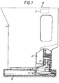
- Fig. 1 shows a cordless hot water jug comprising a jug body 1 placed on a base unit 2.
- An electrical power lead 3 is connected to a female connector socket 4 in the base unit 2.
- a male pin connector 5 projects from the bottom of the jug body 1 for engagement with female socket connector 4 to supply power to the heating element (not shown).
- the jug 1 contains an overheat protection control unit 6 as is standard in the art, and also a vapour activated boiling control 7 (shown schematically) arranged in the upper part of the jug body 1 and which is in fluid communication with the liquid containing space of the jug body 1.
- the boiling control is of the general type previously described, having a snap-acting bimetallic actuator, and is arranged in the power supply to the element such that when it is activated by the steam produced when water in the jug boils, it interrupts the power supply to deactivate the element.
- the boiling control may be arranged as part of the overheat protector, with suitable ducting in the vessel walls to conduct vapour thereto. When it is desired to re-boil the jug, the control is reset manually using the on-off knob 8.
- a thermally sensitive control 20 for de-energising the element when the water in the jug reaches a predetermined temperature below boiling, is arranged in the base unit 2.
- the control 20 is placed electrically in series with the female socket connector, and comprises a bimetallic actuator 21 which is movably mounted beneath a small metal plate 9 provided in the upper part of a tapering, square boss 10 extending from the upper surface 11 of the base 2.
- the metal plate 9 is arranged directly to engage the underside of the base wall of the jug 1 when it is placed on the base unit 2.
- the base wall may include a region of reduced thickness adjacent the point of engagement with the plate 9 or alternatively a metal insert could be provided in the base wall to ensure adequate thermal contact in use between the plate 9 and the liquid within the jug. In the case of a metal jug or kettle, good thermal contact would be achieved in any event.
- the control 20 comprises a cylindrical body portion 22, having a snap-action bimetallic actuator 21 secured on its upper surface by an annular retaining member 23.
- the bimetallic actuator 21 reverses its curvature with a snap-action to push downwardly a push rod 24 to open a set of resiliently biased contacts 25 provided at the respective ends of conductive strips 26,27, provided with connector tabs 28 for connection into the line side of the electrical supply to the connector 4.
- the whole control 20 is movable between a raised position (Fig.
- the unit 20 is movable through cam means by an operating lever 12 slidable in a slot 13 in the wall of the base 2.
- the cam means comprises a pair of diametrically opposed pins 29 extending radially from the cylindrical body portion 22 which engage with helical grooves 30 formed in a skirt 31 depending from the raised boss 10.
- the slot 13 is marked at one end with “black coffee”, at the other end with “tea” and at an intermediate position with “white coffee”, and notches 14 are provided at each location to retain the lever 12 at that location.
- the actuator assumes its raised position (Fig. 5A), in which it directly engages the plate 9 and is in good thermal contact with the base of a jug placed on the base unit 2.
- the thermally-sensitive control disconnects the power supply to the heating element when the desired predetermined water temperature, suitable for black coffee making (typically 80-85°C) is reached.
- the operating temperature of the actuator will vary depending on how good the thermal contact between it and the liquid is. For a metal jug, or one having a metal insert as discussed, the temperature of the actuator may not lag significantly behind that of the liquid during heating, and an operating temperature of about 80°C may be suitable. Where thermal contact between the liquid and actuator is achieved via a plastic jug base, a lower operating temperature of the actuator will be appropriate e.g. around 60°C. In the "tea" position (Fig.
- the actuator is displaced away from the plate 9 and will not, therefore, be in good thermal contact with the liquid in the jug 1. It will therefore not be heated sufficiently to operate the thermally-sensitive control before water boils in the jug 1, at which time the boiling control 7 will operate to de-energise the heating element in the manner of a traditional electric jug or kettle.
- the actuator In the intermediate "white coffee" position (Fig. 5B), the actuator assumes a position intermediate its two extreme positions whereby it will still be heated by the liquid in the jug, but more slowly than when it is in direct engagement with the plate 9, whereby the thermally-sensitive control will operate at a water temperature above the "black coffee" temperature but below boiling point, say at 90°C.
- the thermally-sensitive control illustrated will automatically reset when the sensed temperature falls below the respective predetermined temperature so that in the "black coffee” or “white coffee” conditions, the heater cycles to main water within the jug 1 at about the desired, appropriate temperature.
- a modified base unit may be used with a substantially standard form of jug to render it operable at lower temperatures.
- Figs 6 to 8 show a further embodiment of the invention, applied to a corded hot water jug.
- Fig 6 shows a jug body 100 with its control cover/handle housing 101 removed to expose the jug control 102.
- the control 102 is shown in more detail in Figs. 7 and 8, and comprises a conventional control unit 103 (sold under the applicant's commercial code R72) shown generally in chain lines, which combines the features of a boiling control, a primary overheat protector and a secondary, back-up protector. Such a control is described for example in GB-A-2181598.
- the control unit 103 includes a manually-resettable over-centre spring mechanism 104 which is acted upon by a bimetallic actuator (not shown) mounted at the upper part of the control body 105 and which is exposed, through suitable passageways in the wall of the jug body 100, to steam produced within the jug body when water with the jug body boils.
- the bimetallic actuator When the bimetallic actuator operates it acts upon the upper arm 106 of a sprung, over-centre lever member 107 to cause it to pivot over-centre in the direction of arrow A.
- a lower arm 108 of the over-centre lever member 107 then acts, through a suitable linkage to open a set of electrical contacts in the control, so as to disconnect the power supply to the jug element.
- the over-centre lever member 107 To re-connect the power supply, the over-centre lever member 107 must be pushed back over-centre in the direction of arrow B.
- a further, thermally sensitive control 110 is mounted on the control unit 103.
- the thermally-sensitive control 110 comprises a support body 111, having a mounting bore 112 which fits over a boss 113 formed on the control body 105 of the control unit 103.
- the support body 111 is suitably shaped to conform to the profile of the control body 105 so as to be located thereon in the correct angular orientation.
- a screw (not shown) for mounting the cover housing 101 extend into the boss 113 and the support body 111 will be clamped in position thereby.
- a pivot lever member 114 is mounted to the support body 111 by two clasps 115 (only one shown) arranged on opposite sides of the mounting bore 112.
- One arm 116 of the pivot lever member 114 extends through a slot 117 formed in the rear of a laterally extending lug 118 of the support body 111, and abuts a bimetallic actuator 119 which is mounted in this lug 118 by an annular retaining member 120.
- the actuator 119 is chosen to operate at a desired temperature below 100°C.
- the lug locates in a recess 135 formed in the vessel body wall 100 by local thinning thereof. By thinning the vessel wall in this region, heat transfer to the bimetallic actuator 119 is improved.
- the other arm 121 of the lever member 114 extends to the region of the lower arm 108 of the over-centre lever member 107.
- a pivot surface or block 130 is formed on the arm 121.
- the support body 111 also comprises a bifurcated arm 122 upon which is slidably mounted a control member 123.
- the control member 123 is generally L-shaped and comprises a pivot surface 124 slidable along the back of the arm 122.
- the bifurcated arm 122 exerts a resilient force on the control member 123. When the jug is assembled the control member 123 extends through a slot 125 provided in the control housing 101.
- control member 123 is slidable from a first, tea making, position (Fig 8B) in which the pivot surface 124 is displaced from and does not contact the pivot surface 130 formed on the arm 121 of the lever member 124, and a second, coffee making, position (Fig 8C) in which it does.
- the lever member 114 In the first position, (in which the control member will be positioned at the end of the slot 125 marked "tea") when the bimetallic actuator operates, reversing its curvature with a snap action, the lever member 114 is moved away from the jug body wall without pivoting so that the arm 108 of the over-centre lever member 107 will not be acted upon by the arm 121 of the lever member 114 to cause it to trip.
- the arm 108 will instead be tripped by the action of the steam sensitive bimetallic actuator, when liquid in the vessel boils.
- the pivot surfaces 124, 130 together form a pivot axis P about which the lever member 114 may pivot.
- the lever member 114 will then pivot about the axis P to trip the arm 108, and thus disconnect the power supply to the heater of the jug.
- the thermally-sensitive control of this embodiment does not cycle but rather, to re-connect the power supply to the heater, the over-centre lever member 107 must be reset manually by a user.
- the thermally-sensitive control acts to open a set of contacts also opened by the boiling control, this is of course not essential.
- the thermally-sensitive control may be adapted to open contacts provided within the overheat protector unit through a suitable linkage.
Abstract
Description
- The present invention relates to liquid heating vessels which are required to heat a liquid to its boiling point and also to a lower temperature. It is particularly, but not exclusively, applicable to electric water heating vessels such as kettles and jugs which are used in making hot beverages such as tea and coffee.
- While it is desirable that boiling water should be used for making tea, it is generally considered that water used in making coffee should ideally be somewhat below boiling, for example at 80°C to 90°C. Accordingly, it is common when making a coffee beverage to allow a boiled kettle or jug to stand for some time before pouring it on to the coffee. Alternatively, cold water can be added to the boiled water in the kettle or jug prior to pouring to reduce it to approximately the correct temperature. Both of these approaches are clearly inconvenient for the user, and whether or not the desired temperature is achieved can be a hit or miss affair.
- It has also been proposed recently, in our UK Patent Application No. 9105718.2 (GB-A-2242614), to provide an electric kettle or jug which is divided internally by a partition arranged such that water is heated to different temperatures on either side of the partition and in particular when water on one side boils to provide vapour which causes an automatic steam sensitive switch to deactivate the heater, water on the other side of the partition is at a lower temperature. The arrangement is such that mixing then occurs on pouring to give water of an intermediate temperature, for use in making coffee. To provide boiling water, an opening is made in the partition to allow the water in both chambers to mix by convection during heating so that substantially all the water is at the boiling point by the time the heater is deactivated by the steam sensitive switch. This arrangement has the disadvantage however that the interior of the jug or kettle must be specially modified.
- It is also known to provide thermostats in some vessels (though typically not household jugs or kettles) to control water temperature at different predetermined temperatures. However, such thermostats can be relatively costly, and are inherently unsuited for use where one of the predetermined temperatures is intended to be the boiling point of the liquid since the boiling point varies depending on atmospheric pressure and altitude and on the hardness of the water, for example.
- According to the present invention there is provided liquid heating apparatus comprising a liquid heating vessel having an electric heater, a manually resettable boiling control comprising an actuator exposed to steam or vapour resulting from liquid within the container boiling and coupled to an electrical switch means for interrupting the power supply to said heater when the liquid in said vessel boils, a thermally-sensitive control including an actuator arranged or arrangeable in thermal contact with liquid within said vessel and operable to interrupt the power supply to said heater at a predetermined liquid temperature which is below the boiling point, and means for selectively rendering the thermally-sensitive control inoperable or operable so that the vessel may be adapted to provide liquid at or below its boiling point as desired.
- Thus in accordance with the invention controls are provided for boiling a liquid, for example water, and for heating the liquid to a predetermined lower temperature. When it is desired to boil liquid in the vessel, which may be a hot water jug or kettle, the thermally-sensitive control is rendered inoperative, and the heater will be disconnected by the manually resettable boiling control in the manner of a traditional electric kettle or jug. However when liquid of a lower temperature is required eg. for making coffee, the thermally-responsive control is rendered operative so that the heater will be disabled by that control at the desired lower temperature. This overcomes the problems with thermostatic calibration mentioned above, and enables the cost-effective adaptation of jugs and kettles fitted with vapour activated boiling controls enabling them to be capable of selectively producing lower temperature liquid.
- Vapour activated boiling controls are well known in the art, and are already used on large numbers of jugs and kettles. Typically such controls may comprise a bimetallic actuator upon which vapour or steam produced by the liquid boiling in the vessel impinges. The actuator is heated by the vapour condensing thereon, and when its temperature has risen sufficiently, it will operate to trip an over-centre lever which in turn cooperates with and opens a set of switch contacts in the power supply to the heater. Such controls are shown, for example, in our earlier UK Patent Applications GB 2221795, GB2215134, and UK Patent 1470367. The thermally-sensitive control may be of any construction which when operable will provide disconnection of the power supply to the heater when the liquid is at the desired temperature. Although the control may be such that once it operates, it must be positively reset by a user to reconnect the power supply to the heater, in one embodiment the control resets automatically when the sensed temperature falls below a given value whereby the control will cycle to maintain the liquid in the vessel at approximately the desired predetermined temperature.
- Furthermore, the thermally-sensitive control may be variable so that it may be set to operate at a variable desired liquid temperature. This may be useful if, for example, it is desired to produce white coffee with cold milk or cream which ideally requires non-boiling liquid of a somewhat higher temperature than black coffee, for example.
- The means for rendering the thermally-sensitive control inoperative may vary. For example, it may comprise an electrical switch means for effectively bypassing the control. A further suitable means is adapted thermally to isolate the actuator of the control from liquid in the vessel, for example by interposing an insulating member between the actuator and the liquid, or by distancing the actuator from the liquid. In this way, although still connected electrically in the power supply to the heater the control will not operate to disconnect the heater before the boiling control operates. In an alternative system, a mechanical link between the actuator of the thermally-sensitive control and its electrical switch means may selectively be rendered ineffective.
- The actuators of the boiling and thermally-sensitive controls may be located in any suitable position, and the controls may both be mounted to the vessel. The actuator of the thermally-sensitive control, when operable, may be located in the liquid, or may be in thermal contact therewith eg. via a base or side wall of the vessel. In the case of a plastic vessel, thermal contact between the liquid and the actuator may be improved by including a thinner vessel wall portion, or a metal insert therein, in the vicinity of the actuator. The invention may also be readily embodied in so-called "cordless" electrical jugs or kettles wherein the heating vessel, rather than having a power lead directly connected to it, is removably locatable on a base unit to which the power supply is connected, and has an electrical connector for engagement with a corresponding connector on the base unit, to supply power to the heater. In accordance with a preferred embodiment of the invention, the boiling control is provided on the vessel itself while the thermally-sensitive control is provided in the base unit.
- Preferably the thermally-sensitive control comprises an actuator mounted in an upper part of the base unit so that when the vessel is placed thereon, with the control in its operable condition, the actuator is placed in thermal contact with the base wall of the heating vessel to be responsive to the temperature of the liquid therethrough. Further, the actuator may be mounted in the base unit so as to be movable towards and away from the base of the heating vessel, such that when boiling liquid is required the actuator is sufficiently thermally isolated from the base of the heating vessel so that it will not operate before the liquid temperature in the vessel reaches its boiling point. The actuator may be moved by a cam connected to an operating lever provided on the base. An intermediate position or positions of the actuator may be provided whereby liquid may be heated to more than one predetermined temperatures below the boiling point e.g. for making black or white coffee as discussed above. In a preferred embodiment, the actuator is mounted within an upward projection in the base unit, and in its raised position directly engages a metal plate at the top of such projection which in turn directly engages the underside of the vessel in use.
- In the case of a household kettle or jug, a preferred thermally-sensitive control may be adapted to heat the water to around 80 to 85°C for black coffee, and to around 90°C for white coffee.
- As mentioned above, the form of the thermally-sensitive control may vary. An electronic control could be used incorporating an actuator in the form of a thermocouple, for example. In a preferred embodiment, however, this control also comprises a bimetallic actuator, which at a certain nominal operating temperature displaces, preferably by snap action, to open a set of switch contacts of the control to interrupt the power supply to the heater. Controls of this general type are well known. Since the temperature of the bimetallic actuator will lag somewhat behind the actual temperature of the liquid in the vessel, the operating temperature of the bimetal will typically be somewhat below the desired predetermined temperature of the liquid depending on the degree of thermal contact between the liquid and the actuator. As discussed above, the bimetallic actuator is preferably arranged to cycle so that the switch contacts open and close and the heater operates intermittently to maintain the liquid at about the predetermined temperature if the vessel is left unattended.
- In a further embodiment, which may be applied to a traditional jug or kettle as well as a cordless one, the actuator of the thermally-sensitive control, which in this system preferably is mounted in thermal contact with a side wall of the container, is coupled mechanically to an over-centre lever forming part of the boiling control, whereby in its operable condition the actuator of the thermally-sensitive control is adapted to trip the lever and disable the heater in the same manner as the boiling control. In such an arrangement, it will be appreciated that the thermally-sensitive control as defined herein shows certain components with the boiling control i.e. the over-centre lever and the associated switch contacts. Such system may include a mechanical link between the actuator and the over-centre lever which can be disengaged therefrom by suitable means for making tea, whereupon the over-centre lever will be tripped by the steam sensitive actuator in the normal way upon boiling.
- In a preferred embodiment, the actuator of the thermally-sensitive control is coupled to the over-centre lever by means of a lever member which is selectively pivotable about an axis. Preferably, a pivot surface which is selectively engageable with and disengageable from a pivot provided on the lever is provided on a control member. The control member is preferably mounted on a support member so as to be slidably movable between the engaged and disengaged positions, and may extend through a suitable slot in a housing of the kettle or jug for operation by a user. When the pivot surface and pivot engage, operation of the actuator causes pivoting of the arm to trip the over-centre mechanism, but when they are disengaged, no pivotal movement takes place and the over-centre mechanism will instead be tripped by the boiling control actuator. Preferably the support member, lever and actuator are mountable as a unit to the boiling control. This allows a thermally-sensitive control to be added to a standard boiling control which may form part of an integrated control unit comprising also primary overheat and back-up protectors, as is well known in the art.
- It will be appreciated that the invention also extends to a combined boiling and thermally-sensitive control for a liquid heading vessel having an electric heater, comprising a manually resettable boiling control comprising an actuator exposed, in use, to steam or vapour resulting from liquid within the container boiling, and coupled to an electrical switch means for interrupting the power supply to said heater when the liquid in said vessel boils, and a thermally-sensitive control including an actuator arranged in use in thermal contact with liquid within said vessel and operable to interrupt the power supply to said heater at a predetermined liquid temperature which is below the boiling point, and means for selectively rendering the thermally-sensitive control inoperable or operable so that the vessel may be adapted to provide liquid at or below its boiling point as desired. Preferably said thermal-sensitive control is adapted to be be mountable to said boiling control as a unit.
- As in the arrangement described above, the thermally-sensitive control may be coupled mechanically to an over-centre mechanism of the boiling control whereby operation thereof opens the boiling contacts. Other preferred features of the thermally-sensitive control may be as described above.
- From a third aspect, the invention also extends to a thermally-sensitive control for a liquid heating vessel, adapted to disconnect the power supply to an electric heater thereof at a temperature below the boiling point of the liquid, comprising a bimetallic actuator for thermal engagement with a wall of the vessel, a lever member acted upon by said actuator when it operates and selectively pivotable about an axis for opening a set of contacts in the power supply to a heater of said vessel and a control member having a pivot surface and which is selectively movable between positions in which said pivot surface is engaged with or disengaged from a pivot surface provided on the lever member, said control being mountable to said vessel or a control thereof.
- Some preferred embodiments of the invention will now be described, by way of example only, with reference to the accompanying drawings in which:
- Fig. 1 shows a known cordless hot water jug to which the invention is applied; and
- Fig. 2 shows schematically a modified base unit for use with the jug of Fig. 1, in accordance with the invention.
- Fig. 3 shows, schematically, an exploded view of the thermally-sensitive control shown in Fig. 2;
- Figs. 4A and 4B show the thermally-sensitive control of Fig. 3 in two operating conditions;
- Figs. 5A to 5C show different positions of the thermally-sensitive control;
- Fig. 6 shows a hot water jug embodying a second embodiment of the invention;
- Fig. 7 shows the control shown in Fig. 6 in greater detail;
- Fig. 8A shows a schematic, part sectional view of Fig. 7, looking from below; and
- Figs. 8B and 8C show the control of Figs. 7 and 8A in two operating conditions.
- Fig. 1 shows a cordless hot water jug comprising a jug body 1 placed on a
base unit 2. Anelectrical power lead 3 is connected to afemale connector socket 4 in thebase unit 2. Amale pin connector 5 projects from the bottom of the jug body 1 for engagement withfemale socket connector 4 to supply power to the heating element (not shown). The jug 1 contains an overheat protection control unit 6 as is standard in the art, and also a vapour activated boiling control 7 (shown schematically) arranged in the upper part of the jug body 1 and which is in fluid communication with the liquid containing space of the jug body 1. The boiling control is of the general type previously described, having a snap-acting bimetallic actuator, and is arranged in the power supply to the element such that when it is activated by the steam produced when water in the jug boils, it interrupts the power supply to deactivate the element. Of course, the boiling control may be arranged as part of the overheat protector, with suitable ducting in the vessel walls to conduct vapour thereto. When it is desired to re-boil the jug, the control is reset manually using the on-offknob 8. - Turning now to Fig. 2, a modified
base unit 2 is shown. In this embodiment of the invention, a thermallysensitive control 20, for de-energising the element when the water in the jug reaches a predetermined temperature below boiling, is arranged in thebase unit 2. Thecontrol 20 is placed electrically in series with the female socket connector, and comprises abimetallic actuator 21 which is movably mounted beneath asmall metal plate 9 provided in the upper part of a tapering,square boss 10 extending from the upper surface 11 of thebase 2. Themetal plate 9 is arranged directly to engage the underside of the base wall of the jug 1 when it is placed on thebase unit 2. In the case of a plastic jug, the base wall may include a region of reduced thickness adjacent the point of engagement with theplate 9 or alternatively a metal insert could be provided in the base wall to ensure adequate thermal contact in use between theplate 9 and the liquid within the jug. In the case of a metal jug or kettle, good thermal contact would be achieved in any event. - As can be seen in more detail from Figs. 3 to 5, the
control 20 comprises acylindrical body portion 22, having a snap-actionbimetallic actuator 21 secured on its upper surface by anannular retaining member 23. As can be seen from Figs 4A and 4B, upon operation thebimetallic actuator 21 reverses its curvature with a snap-action to push downwardly a push rod 24 to open a set of resiliently biasedcontacts 25 provided at the respective ends ofconductive strips connector tabs 28 for connection into the line side of the electrical supply to theconnector 4. As will be seen from Figs. 5A to 5C, thewhole control 20 is movable between a raised position (Fig. 5A) in which theactuator 21 directly engages the underside of theplate 9 and in use is thereby placed in good thermal contact with base wall of the jug and with the liquid therein, and one or more retracted positions (Figs. 5B,5C) in which it is spaced from the plate and is thermally more isolated from the liquid. - The
unit 20 is movable through cam means by an operatinglever 12 slidable in aslot 13 in the wall of thebase 2. The cam means comprises a pair of diametricallyopposed pins 29 extending radially from thecylindrical body portion 22 which engage withhelical grooves 30 formed in askirt 31 depending from the raisedboss 10. Theslot 13 is marked at one end with "black coffee", at the other end with "tea" and at an intermediate position with "white coffee", andnotches 14 are provided at each location to retain thelever 12 at that location. When the lever 11 is at the "black coffee" position, the actuator assumes its raised position (Fig. 5A), in which it directly engages theplate 9 and is in good thermal contact with the base of a jug placed on thebase unit 2. It will thus be heated as the temperature of water in the jug 1 increases, and has an operating temperature selected such that the thermally-sensitive control disconnects the power supply to the heating element when the desired predetermined water temperature, suitable for black coffee making (typically 80-85°C) is reached. The operating temperature of the actuator will vary depending on how good the thermal contact between it and the liquid is. For a metal jug, or one having a metal insert as discussed, the temperature of the actuator may not lag significantly behind that of the liquid during heating, and an operating temperature of about 80°C may be suitable. Where thermal contact between the liquid and actuator is achieved via a plastic jug base, a lower operating temperature of the actuator will be appropriate e.g. around 60°C. In the "tea" position (Fig. 5C) the actuator is displaced away from theplate 9 and will not, therefore, be in good thermal contact with the liquid in the jug 1. It will therefore not be heated sufficiently to operate the thermally-sensitive control before water boils in the jug 1, at which time the boilingcontrol 7 will operate to de-energise the heating element in the manner of a traditional electric jug or kettle. In the intermediate "white coffee" position (Fig. 5B), the actuator assumes a position intermediate its two extreme positions whereby it will still be heated by the liquid in the jug, but more slowly than when it is in direct engagement with theplate 9, whereby the thermally-sensitive control will operate at a water temperature above the "black coffee" temperature but below boiling point, say at 90°C. - The thermally-sensitive control illustrated will automatically reset when the sensed temperature falls below the respective predetermined temperature so that in the "black coffee" or "white coffee" conditions, the heater cycles to main water within the jug 1 at about the desired, appropriate temperature.
- An important advantage of the illustrated arrangement is that a modified base unit may be used with a substantially standard form of jug to render it operable at lower temperatures.
- Figs 6 to 8 show a further embodiment of the invention, applied to a corded hot water jug.
- Fig 6 shows a
jug body 100 with its control cover/handle housing 101 removed to expose thejug control 102. - The
control 102 is shown in more detail in Figs. 7 and 8, and comprises a conventional control unit 103 (sold under the applicant's commercial code R72) shown generally in chain lines, which combines the features of a boiling control, a primary overheat protector and a secondary, back-up protector. Such a control is described for example in GB-A-2181598. Thecontrol unit 103 includes a manually-resettableover-centre spring mechanism 104 which is acted upon by a bimetallic actuator (not shown) mounted at the upper part of the control body 105 and which is exposed, through suitable passageways in the wall of thejug body 100, to steam produced within the jug body when water with the jug body boils. When the bimetallic actuator operates it acts upon theupper arm 106 of a sprung,over-centre lever member 107 to cause it to pivot over-centre in the direction of arrow A. Alower arm 108 of theover-centre lever member 107 then acts, through a suitable linkage to open a set of electrical contacts in the control, so as to disconnect the power supply to the jug element. To re-connect the power supply, theover-centre lever member 107 must be pushed back over-centre in the direction of arrow B. - To allow the
jug 100 to be used to heat water to a predetermined lower temperature, a further, thermallysensitive control 110 is mounted on thecontrol unit 103. - The thermally-
sensitive control 110 comprises a support body 111, having a mountingbore 112 which fits over a boss 113 formed on the control body 105 of thecontrol unit 103. The support body 111 is suitably shaped to conform to the profile of the control body 105 so as to be located thereon in the correct angular orientation. In use, a screw (not shown) for mounting thecover housing 101 extend into the boss 113 and the support body 111 will be clamped in position thereby. - A
pivot lever member 114 is mounted to the support body 111 by two clasps 115 (only one shown) arranged on opposite sides of the mountingbore 112. Onearm 116 of thepivot lever member 114 extends through aslot 117 formed in the rear of a laterally extendinglug 118 of the support body 111, and abuts abimetallic actuator 119 which is mounted in thislug 118 by anannular retaining member 120. Theactuator 119 is chosen to operate at a desired temperature below 100°C. As can be seen from Fig 8A the lug locates in a recess 135 formed in thevessel body wall 100 by local thinning thereof. By thinning the vessel wall in this region, heat transfer to thebimetallic actuator 119 is improved. Theother arm 121 of thelever member 114 extends to the region of thelower arm 108 of theover-centre lever member 107. A pivot surface or block 130 is formed on thearm 121. - The support body 111 also comprises a
bifurcated arm 122 upon which is slidably mounted acontrol member 123. Thecontrol member 123 is generally L-shaped and comprises apivot surface 124 slidable along the back of thearm 122. Thebifurcated arm 122 exerts a resilient force on thecontrol member 123. When the jug is assembled thecontrol member 123 extends through aslot 125 provided in thecontrol housing 101. - As can be seen from Figs. 8B and 8C, the
control member 123 is slidable from a first, tea making, position (Fig 8B) in which thepivot surface 124 is displaced from and does not contact thepivot surface 130 formed on thearm 121 of thelever member 124, and a second, coffee making, position (Fig 8C) in which it does. In the first position, (in which the control member will be positioned at the end of theslot 125 marked "tea") when the bimetallic actuator operates, reversing its curvature with a snap action, thelever member 114 is moved away from the jug body wall without pivoting so that thearm 108 of theover-centre lever member 107 will not be acted upon by thearm 121 of thelever member 114 to cause it to trip. Thearm 108 will instead be tripped by the action of the steam sensitive bimetallic actuator, when liquid in the vessel boils. However, in the second position (in which the control member is at the other end of theslot 125, marked "coffee") the pivot surfaces 124, 130 together form a pivot axis P about which thelever member 114 may pivot. Thus when thebimetallic actuator 119 operates, thelever member 114 will then pivot about the axis P to trip thearm 108, and thus disconnect the power supply to the heater of the jug. - Unlike the first embodiment described, the thermally-sensitive control of this embodiment does not cycle but rather, to re-connect the power supply to the heater, the
over-centre lever member 107 must be reset manually by a user. - Whilst in the embodiment described above, the thermally-sensitive control acts to open a set of contacts also opened by the boiling control, this is of course not essential. In an arrangement for example in which a jug or kettle is provided with an overheat protector unit comprising primary and back-up controls which operate in the event that the jug element overheats, and with a remote boiling control (for example in a position as shown schematically in Fig. 1) the thermally-sensitive control may be adapted to open contacts provided within the overheat protector unit through a suitable linkage.
Claims (19)
- A liquid heating apparatus comprising a liquid heating vessel having an electric heater, a manually resettable boiling control comprising an actuator exposed to steam or vapour resulting from liquid within the container boiling and coupled to an electrical switch means for interrupting the power supply to said heater when the liquid in said vessel boils, a thermally-sensitive control including an actuator arranged or arrangeable in thermal contact with liquid within said vessel and operable to interrupt the power supply to said heater at a predetermined liquid temperature which is below the boiling point, and means for selectively rendering the thermally-sensitive control inoperable or operable so that the vessel may be adapted to provide liquid at or below its boiling point as desired.
- A liquid heater apparatus as claimed in claim 1 wherein said means for rendering said thermally-sensitive control inoperable or operable comprises means for selectively thermally isolating the actuator of said control from the liquid in the vessel.
- A liquid heater apparatus as claimed in claim 2 wherein said isolating means comprises means for selectively distancing the actuator from the liquid.
- A liquid heater apparatus as claimed in any preceding claim wherein the heating vessel is removably locatable on a base unit to which the power supply is connected, and which has an electrical connector for engagement with a corresponding connector on the base unit, to supply power to the heater, and wherein said thermally-sensitive control is arranged in said base unit.
- A liquid heater apparatus as claimed in claim 4 wherein said thermally-sensitive control comprises an actuator mounted in an upper part of the base unit so that when the vessel is placed thereon, with the control in its operable condition, the actuator is placed in thermal contact with the base wall of the heating vessel to be responsive to the temperature of the liquid therethrough.
- A liquid heater apparatus as claimed in claims 3 and 5 wherein said actuator is mounted in the base unit so as to be movable towards and away from the base of the heating vessel, such that when boiling liquid is required the actuator is sufficiently thermally isolated from the base of the heating vessel so that it will not operate before the liquid temperature in the vessel reaches its boiling point.
- A liquid heater apparatus as claimed in any preceding claim wherein said thermally-sensitive control cycles so as to maintain the liquid in the vessel at said predetermined lower temperature.
- A liquid heater apparatus as claimed in any one of claims 1 to 3 wherein said thermally-sensitive control is provided on said liquid heating vessel.
- A liquid heater apparatus as claimed in claim 8 wherein said thermally-sensitive control is coupled mechanically to an over-centre lever forming part of the boiling control, whereby in its operable condition the actuator of the thermally-sensitive control is adapted to trip the lever and disable the heater in the same manner as the boiling control.
- A liquid heater apparatus as claimed in claim 9 comprising a mechanical link between the actuator and the over-centre lever which can be disengaged therefrom by suitable means.
- A liquid heater apparatus as claimed in claim 10 wherein said mechanical linkage comprises a lever member which is selectively pivotable about a pivot axis.
- A liquid heater apparatus as claimed in claim 11 comprising a control member having a pivot surface for selective engagement with a pivot surface provided on said lever member to form said pivot axis.
- A liquid heater apparatus as claimed in any of claims 8 to 12 wherein said thermally-sensitive control is mounted or mountable as a unit to the boiling control or to a control unit including said boiling control.
- A combined boiling and thermally-sensitive control for a liquid heading vessel having an electric heater comprising a manually resettable boiling control comprising an actuator exposed, in use, to steam or vapour resulting from liquid within the container boiling, and coupled to an electrical switch means for interrupting the power supply to said heater when the liquid in said vessel boils, and a thermally-sensitive control including an actuator arrangeable in use in thermal contact with liquid within said vessel and operable to interrupt the power supply to said heater at a predetermined liquid temperature which is below the boiling point, and means for selectively rendering the thermally-sensitive control inoperable or operable so that the vessel may be adapted to provide liquid at or below its boiling point as desired.
- A combined boiling and thermally-sensitive control as claimed in claim 14 wherein said thermally-sensitive control is mounted to said boiling control as a unit.
- A combined boiling and thermally-sensitive control as claimed in claim 14 or 15 wherein said control comprises an over-centre lever, and further comprising a mechanical link between the actuator of said thermally-sensitive control and the over-centre lever which can be disengaged therefrom by suitable means.
- A combined boiling and thermally-sensitive control as claimed in claim 16 wherein said mechanical linkage comprises a lever member which is selectively pivotable about a pivot axis.
- A combined boiling and thermally-sensitive control as claimed in claim 17 comprising a control member having a pivot surface for selective engagement with a pivot surface provided on said lever member to form said pivot axis.
- A thermally-sensitive control for a liquid heating vessel, adapted to disconnect the power supply to an electric heater thereof at a temperature below the boiling point of the liquid, comprising a bimetallic actuator for thermal engagement with a wall of the vessel, a lever member acted upon by said actuator when it operates, and selectively pivotable about a pivot axis for opening a set of contacts in the power supply to a heater of said vessel, and a control member having a pivot surface and which is selectively movable between positions in which said surface is engaged with or disengaged from a pivot surface on the lever member, said control being mountable to said vessel or a control thereof.
Applications Claiming Priority (2)
| Application Number | Priority Date | Filing Date | Title |
|---|---|---|---|
| GB919117415A GB9117415D0 (en) | 1991-08-12 | 1991-08-12 | Liquid heating vessels |
| GB9117415 | 1991-08-12 |
Publications (2)
| Publication Number | Publication Date |
|---|---|
| EP0528656A1 true EP0528656A1 (en) | 1993-02-24 |
| EP0528656B1 EP0528656B1 (en) | 1996-11-06 |
Family
ID=10699878
Family Applications (1)
| Application Number | Title | Priority Date | Filing Date |
|---|---|---|---|
| EP19920307446 Expired - Lifetime EP0528656B1 (en) | 1991-08-12 | 1992-08-12 | Liquid heating vessels |
Country Status (3)
| Country | Link |
|---|---|
| EP (1) | EP0528656B1 (en) |
| DE (1) | DE69215039T2 (en) |
| GB (1) | GB9117415D0 (en) |
Cited By (12)
| Publication number | Priority date | Publication date | Assignee | Title |
|---|---|---|---|---|
| WO1995019129A1 (en) * | 1994-01-13 | 1995-07-20 | Strix Limited | Water heating apparatus |
| WO1997021374A1 (en) * | 1995-12-14 | 1997-06-19 | Strix Limited | Controls for liquid heating vessels |
| GB2316229A (en) * | 1996-08-08 | 1998-02-18 | Otter Controls Ltd | Cordless liquid heating appliances |
| GB2325086A (en) * | 1995-12-14 | 1998-11-11 | Strix Ltd | Controls for liquid heating vessels |
| DE19860931A1 (en) * | 1998-12-30 | 2000-07-06 | Efbe Elektrogeraete Gmbh | Kettle with safety shutdown |
| EP1029491A1 (en) * | 1999-02-19 | 2000-08-23 | Seb S.A. | Security and/or control device for an electric cooking apparatus |
| WO2002009561A1 (en) * | 2000-07-25 | 2002-02-07 | Liu, Xinhao | A temperature controller for a liquid heater |
| GB2407478A (en) * | 2003-10-28 | 2005-05-04 | Tarquin Andrew Richard Stehle | Electronically-controlled domestic kettle |
| WO2005059670A1 (en) * | 2003-12-16 | 2005-06-30 | Otter Controls Limited | Improvements relating to thermal controls |
| GB2428893A (en) * | 2003-12-16 | 2007-02-07 | Otter Controls Ltd | Improvements relating to thermal controls |
| GB2439657A (en) * | 2003-12-16 | 2008-01-02 | Otter Controls Ltd | Improvements relating to thermal controls |
| WO2008031253A1 (en) * | 2006-08-15 | 2008-03-20 | Mr Technology (Int'l) Ltd. | Intelligent glass electric heating kettle |
Citations (12)
| Publication number | Priority date | Publication date | Assignee | Title |
|---|---|---|---|---|
| FR973017A (en) * | 1948-10-05 | 1951-02-06 | Metal bimetal thermostatic device | |
| US3147369A (en) * | 1962-11-02 | 1964-09-01 | Lewis L Salton | Temperature control systems |
| GB1470367A (en) | 1974-07-02 | 1977-04-14 | Taylor J | Electric immersion heaters |
| GB2181598A (en) | 1985-10-04 | 1987-04-23 | Strix Ltd | Thermally-sensitive controls |
| GB2189598A (en) * | 1984-10-04 | 1987-10-28 | Tiyoda Seisakusho Kk | Embedding apparatus for preparing microscopic samples |
| GB2215134A (en) | 1988-01-28 | 1989-09-13 | Strix Ltd | Thermally-sensitive control switch |
| GB2221795A (en) | 1988-08-05 | 1990-02-14 | Strix Ltd | Thermally-responsive actuators and switches |
| GB2222025A (en) * | 1988-08-01 | 1990-02-21 | Strix Ltd | Liquid heating container |
| EP0380369A1 (en) * | 1989-01-26 | 1990-08-01 | Otter Controls Limited | Controls for electrically powered heating elements |
| DE3941187A1 (en) * | 1989-12-13 | 1991-06-20 | Bosch Siemens Hausgeraete | Domestic electric water heater with holding temp. regulator - is switched in parallel with series combination of main on=off switch and isolator activated on boiling |
| GB2242614A (en) | 1990-03-23 | 1991-10-09 | Strix Ltd | Liquid heating vessel |
| EP0510863A2 (en) * | 1991-04-22 | 1992-10-28 | Otter Controls Limited | Controls for water heating appliances |
-
1991
- 1991-08-12 GB GB919117415A patent/GB9117415D0/en active Pending
-
1992
- 1992-08-12 EP EP19920307446 patent/EP0528656B1/en not_active Expired - Lifetime
- 1992-08-12 DE DE1992615039 patent/DE69215039T2/en not_active Expired - Fee Related
Patent Citations (12)
| Publication number | Priority date | Publication date | Assignee | Title |
|---|---|---|---|---|
| FR973017A (en) * | 1948-10-05 | 1951-02-06 | Metal bimetal thermostatic device | |
| US3147369A (en) * | 1962-11-02 | 1964-09-01 | Lewis L Salton | Temperature control systems |
| GB1470367A (en) | 1974-07-02 | 1977-04-14 | Taylor J | Electric immersion heaters |
| GB2189598A (en) * | 1984-10-04 | 1987-10-28 | Tiyoda Seisakusho Kk | Embedding apparatus for preparing microscopic samples |
| GB2181598A (en) | 1985-10-04 | 1987-04-23 | Strix Ltd | Thermally-sensitive controls |
| GB2215134A (en) | 1988-01-28 | 1989-09-13 | Strix Ltd | Thermally-sensitive control switch |
| GB2222025A (en) * | 1988-08-01 | 1990-02-21 | Strix Ltd | Liquid heating container |
| GB2221795A (en) | 1988-08-05 | 1990-02-14 | Strix Ltd | Thermally-responsive actuators and switches |
| EP0380369A1 (en) * | 1989-01-26 | 1990-08-01 | Otter Controls Limited | Controls for electrically powered heating elements |
| DE3941187A1 (en) * | 1989-12-13 | 1991-06-20 | Bosch Siemens Hausgeraete | Domestic electric water heater with holding temp. regulator - is switched in parallel with series combination of main on=off switch and isolator activated on boiling |
| GB2242614A (en) | 1990-03-23 | 1991-10-09 | Strix Ltd | Liquid heating vessel |
| EP0510863A2 (en) * | 1991-04-22 | 1992-10-28 | Otter Controls Limited | Controls for water heating appliances |
Cited By (28)
| Publication number | Priority date | Publication date | Assignee | Title |
|---|---|---|---|---|
| WO1995019129A1 (en) * | 1994-01-13 | 1995-07-20 | Strix Limited | Water heating apparatus |
| GB2301226A (en) * | 1994-01-13 | 1996-11-27 | Strix Ltd | Water heating apparatus |
| GB2301226B (en) * | 1994-01-13 | 1998-04-22 | Strix Ltd | Control units for water heating apparatus |
| WO1997021374A1 (en) * | 1995-12-14 | 1997-06-19 | Strix Limited | Controls for liquid heating vessels |
| CN100337571C (en) * | 1995-12-14 | 2007-09-19 | 斯特里克斯有限公司 | Controls for liquid heating vessels |
| GB2325086A (en) * | 1995-12-14 | 1998-11-11 | Strix Ltd | Controls for liquid heating vessels |
| GB2325086B (en) * | 1995-12-14 | 2000-02-02 | Strix Ltd | Controls for liquid heating vessels |
| GB2316229A (en) * | 1996-08-08 | 1998-02-18 | Otter Controls Ltd | Cordless liquid heating appliances |
| GB2316229B (en) * | 1996-08-08 | 2000-10-11 | Otter Controls Ltd | Improvements relating to liquid heating appliances and controls therefor |
| WO2000040128A1 (en) * | 1998-12-30 | 2000-07-13 | Efbe Elektrogeräte GmbH | Kettle with security cut-off |
| DE19860931A1 (en) * | 1998-12-30 | 2000-07-06 | Efbe Elektrogeraete Gmbh | Kettle with safety shutdown |
| EP1029491A1 (en) * | 1999-02-19 | 2000-08-23 | Seb S.A. | Security and/or control device for an electric cooking apparatus |
| FR2789871A1 (en) * | 1999-02-19 | 2000-08-25 | Seb Sa | SAFETY AND / OR CONTROL DEVICE FOR ELECTRIC COOKING APPARATUS |
| US6268591B1 (en) | 1999-02-19 | 2001-07-31 | Seb S.A. | Safety and/or control device for electric cooking appliance |
| WO2002009561A1 (en) * | 2000-07-25 | 2002-02-07 | Liu, Xinhao | A temperature controller for a liquid heater |
| GB2407478A (en) * | 2003-10-28 | 2005-05-04 | Tarquin Andrew Richard Stehle | Electronically-controlled domestic kettle |
| GB2407478B (en) * | 2003-10-28 | 2005-09-28 | Tarquin Andrew Richard Stehle | Domestic electronic kettle |
| GB2428893A (en) * | 2003-12-16 | 2007-02-07 | Otter Controls Ltd | Improvements relating to thermal controls |
| GB2428894A (en) * | 2003-12-16 | 2007-02-07 | Otter Controls Ltd | Improvements relating to thermal controls |
| WO2005059670A1 (en) * | 2003-12-16 | 2005-06-30 | Otter Controls Limited | Improvements relating to thermal controls |
| GB2428894B (en) * | 2003-12-16 | 2007-10-03 | Otter Controls Ltd | Improvements relating to thermal controls |
| GB2428893B (en) * | 2003-12-16 | 2007-10-03 | Otter Controls Ltd | Improvements relating to thermal controls |
| GB2409343B (en) * | 2003-12-16 | 2007-10-17 | Otter Controls Ltd | Improvements relating to thermal controls |
| GB2439657A (en) * | 2003-12-16 | 2008-01-02 | Otter Controls Ltd | Improvements relating to thermal controls |
| GB2439657B (en) * | 2003-12-16 | 2008-09-17 | Otter Controls Ltd | improvements relating to thermal controls |
| EP2275892A1 (en) | 2003-12-16 | 2011-01-19 | Otter Controls Limited | Thermal control in a liquid heating vessel |
| CN101551679B (en) * | 2003-12-16 | 2011-04-20 | 奥特控制有限公司 | Thermal control and wireless heating vessel |
| WO2008031253A1 (en) * | 2006-08-15 | 2008-03-20 | Mr Technology (Int'l) Ltd. | Intelligent glass electric heating kettle |
Also Published As
| Publication number | Publication date |
|---|---|
| GB9117415D0 (en) | 1991-09-25 |
| DE69215039D1 (en) | 1996-12-12 |
| DE69215039T2 (en) | 1997-03-06 |
| EP0528656B1 (en) | 1996-11-06 |
Similar Documents
| Publication | Publication Date | Title |
|---|---|---|
| US6153859A (en) | Liquid heating vessels | |
| EP0528656B1 (en) | Liquid heating vessels | |
| EP2374381B1 (en) | Liquid heating vessels | |
| EP1064825B1 (en) | Thermally sensitive controls | |
| US4752671A (en) | Electric immersion heating elements and controls therefor | |
| EP0994666A1 (en) | Liquid heating vessels and controls therefor | |
| US20020124735A1 (en) | Electric beverage maker | |
| GB2181598A (en) | Thermally-sensitive controls | |
| EP2275892A1 (en) | Thermal control in a liquid heating vessel | |
| GB2292841A (en) | Contact arrangement for a liquid heating vessel | |
| WO1995019129A1 (en) | Water heating apparatus | |
| EP0764389A1 (en) | Liquid heating vessels | |
| GB2359978A (en) | Controlling electric liquid-heating appliance | |
| EP1586102A2 (en) | Improvements relating to the control of electric heating elements | |
| GB2308743A (en) | Liquid heating vessels | |
| WO1998006309A1 (en) | Improvements relating to liquid heating appliances and controls therefor | |
| EP1702249B1 (en) | Improvements relating to thermal controls | |
| EP1610354B1 (en) | Mounting for a dished bimetallic actuator | |
| GB2333901A (en) | Control device | |
| GB2329523A (en) | Thermally sensitive controls | |
| EP1445985A2 (en) | Electic heaters | |
| GB2173045A (en) | Electric heating elements | |
| GB2404285A (en) | A thermally responsive control for a liquid heating vesel | |
| GB2252875A (en) | Liquid boiling vessels | |
| GB2439657A (en) | Improvements relating to thermal controls |
Legal Events
| Date | Code | Title | Description |
|---|---|---|---|
| PUAI | Public reference made under article 153(3) epc to a published international application that has entered the european phase |
Free format text: ORIGINAL CODE: 0009012 |
|
| AK | Designated contracting states |
Kind code of ref document: A1 Designated state(s): DE FR GB |
|
| 17P | Request for examination filed |
Effective date: 19930507 |
|
| 17Q | First examination report despatched |
Effective date: 19940308 |
|
| GRAG | Despatch of communication of intention to grant |
Free format text: ORIGINAL CODE: EPIDOS AGRA |
|
| GRAH | Despatch of communication of intention to grant a patent |
Free format text: ORIGINAL CODE: EPIDOS IGRA |
|
| RAP1 | Party data changed (applicant data changed or rights of an application transferred) |
Owner name: STRIX LIMITED |
|
| GRAH | Despatch of communication of intention to grant a patent |
Free format text: ORIGINAL CODE: EPIDOS IGRA |
|
| GRAA | (expected) grant |
Free format text: ORIGINAL CODE: 0009210 |
|
| AK | Designated contracting states |
Kind code of ref document: B1 Designated state(s): DE FR GB |
|
| REF | Corresponds to: |
Ref document number: 69215039 Country of ref document: DE Date of ref document: 19961212 |
|
| ET | Fr: translation filed | ||
| PLBE | No opposition filed within time limit |
Free format text: ORIGINAL CODE: 0009261 |
|
| STAA | Information on the status of an ep patent application or granted ep patent |
Free format text: STATUS: NO OPPOSITION FILED WITHIN TIME LIMIT |
|
| 26N | No opposition filed | ||
| REG | Reference to a national code |
Ref country code: GB Ref legal event code: 732E |
|
| REG | Reference to a national code |
Ref country code: GB Ref legal event code: IF02 |
|
| PGFP | Annual fee paid to national office [announced via postgrant information from national office to epo] |
Ref country code: DE Payment date: 20070824 Year of fee payment: 16 |
|
| PGFP | Annual fee paid to national office [announced via postgrant information from national office to epo] |
Ref country code: GB Payment date: 20070806 Year of fee payment: 16 |
|
| PGFP | Annual fee paid to national office [announced via postgrant information from national office to epo] |
Ref country code: FR Payment date: 20070817 Year of fee payment: 16 |
|
| GBPC | Gb: european patent ceased through non-payment of renewal fee |
Effective date: 20080812 |
|
| REG | Reference to a national code |
Ref country code: FR Ref legal event code: ST Effective date: 20090430 |
|
| PG25 | Lapsed in a contracting state [announced via postgrant information from national office to epo] |
Ref country code: FR Free format text: LAPSE BECAUSE OF NON-PAYMENT OF DUE FEES Effective date: 20080901 Ref country code: DE Free format text: LAPSE BECAUSE OF NON-PAYMENT OF DUE FEES Effective date: 20090303 |
|
| PG25 | Lapsed in a contracting state [announced via postgrant information from national office to epo] |
Ref country code: GB Free format text: LAPSE BECAUSE OF NON-PAYMENT OF DUE FEES Effective date: 20080812 |