EP0528259A2 - Elektrischer Verbinder mit verbessertem Verriegelungsmechanismus - Google Patents
Elektrischer Verbinder mit verbessertem Verriegelungsmechanismus Download PDFInfo
- Publication number
- EP0528259A2 EP0528259A2 EP92113287A EP92113287A EP0528259A2 EP 0528259 A2 EP0528259 A2 EP 0528259A2 EP 92113287 A EP92113287 A EP 92113287A EP 92113287 A EP92113287 A EP 92113287A EP 0528259 A2 EP0528259 A2 EP 0528259A2
- Authority
- EP
- European Patent Office
- Prior art keywords
- main body
- latch
- body portion
- portions
- backstop
- Prior art date
- Legal status (The legal status is an assumption and is not a legal conclusion. Google has not performed a legal analysis and makes no representation as to the accuracy of the status listed.)
- Granted
Links
Images









Classifications
-
- H—ELECTRICITY
- H01—ELECTRIC ELEMENTS
- H01R—ELECTRICALLY-CONDUCTIVE CONNECTIONS; STRUCTURAL ASSOCIATIONS OF A PLURALITY OF MUTUALLY-INSULATED ELECTRICAL CONNECTING ELEMENTS; COUPLING DEVICES; CURRENT COLLECTORS
- H01R12/00—Structural associations of a plurality of mutually-insulated electrical connecting elements, specially adapted for printed circuits, e.g. printed circuit boards [PCB], flat or ribbon cables, or like generally planar structures, e.g. terminal strips, terminal blocks; Coupling devices specially adapted for printed circuits, flat or ribbon cables, or like generally planar structures; Terminals specially adapted for contact with, or insertion into, printed circuits, flat or ribbon cables, or like generally planar structures
- H01R12/70—Coupling devices
- H01R12/7005—Guiding, mounting, polarizing or locking means; Extractors
-
- H—ELECTRICITY
- H01—ELECTRIC ELEMENTS
- H01R—ELECTRICALLY-CONDUCTIVE CONNECTIONS; STRUCTURAL ASSOCIATIONS OF A PLURALITY OF MUTUALLY-INSULATED ELECTRICAL CONNECTING ELEMENTS; COUPLING DEVICES; CURRENT COLLECTORS
- H01R12/00—Structural associations of a plurality of mutually-insulated electrical connecting elements, specially adapted for printed circuits, e.g. printed circuit boards [PCB], flat or ribbon cables, or like generally planar structures, e.g. terminal strips, terminal blocks; Coupling devices specially adapted for printed circuits, flat or ribbon cables, or like generally planar structures; Terminals specially adapted for contact with, or insertion into, printed circuits, flat or ribbon cables, or like generally planar structures
- H01R12/70—Coupling devices
- H01R12/7005—Guiding, mounting, polarizing or locking means; Extractors
- H01R12/7011—Locking or fixing a connector to a PCB
-
- H—ELECTRICITY
- H01—ELECTRIC ELEMENTS
- H01R—ELECTRICALLY-CONDUCTIVE CONNECTIONS; STRUCTURAL ASSOCIATIONS OF A PLURALITY OF MUTUALLY-INSULATED ELECTRICAL CONNECTING ELEMENTS; COUPLING DEVICES; CURRENT COLLECTORS
- H01R12/00—Structural associations of a plurality of mutually-insulated electrical connecting elements, specially adapted for printed circuits, e.g. printed circuit boards [PCB], flat or ribbon cables, or like generally planar structures, e.g. terminal strips, terminal blocks; Coupling devices specially adapted for printed circuits, flat or ribbon cables, or like generally planar structures; Terminals specially adapted for contact with, or insertion into, printed circuits, flat or ribbon cables, or like generally planar structures
- H01R12/70—Coupling devices
- H01R12/71—Coupling devices for rigid printing circuits or like structures
- H01R12/72—Coupling devices for rigid printing circuits or like structures coupling with the edge of the rigid printed circuits or like structures
- H01R12/73—Coupling devices for rigid printing circuits or like structures coupling with the edge of the rigid printed circuits or like structures connecting to other rigid printed circuits or like structures
- H01R12/735—Printed circuits including an angle between each other
- H01R12/737—Printed circuits being substantially perpendicular to each other
-
- H—ELECTRICITY
- H01—ELECTRIC ELEMENTS
- H01R—ELECTRICALLY-CONDUCTIVE CONNECTIONS; STRUCTURAL ASSOCIATIONS OF A PLURALITY OF MUTUALLY-INSULATED ELECTRICAL CONNECTING ELEMENTS; COUPLING DEVICES; CURRENT COLLECTORS
- H01R13/00—Details of coupling devices of the kinds covered by groups H01R12/70 or H01R24/00 - H01R33/00
- H01R13/62—Means for facilitating engagement or disengagement of coupling parts or for holding them in engagement
- H01R13/627—Snap or like fastening
Definitions
- the present invention relates to electrical connectors, and more particularly, to electrical connectors which incorporate a metal latch mechanism.
- main circuit boards or “motherboards” employed in computers or other electrical equipment are interconnected to an array of secondary circuit boards.
- secondary boards such as edge cards, single in-line packages (SIP), memory modules, a single in-line memory modules (SIMM) or circuit modules.
- Circuit boards ordinarily comprise a rigid substrate board having a plurality of integrated circuits mounted thereon.
- interconnection between a main circuit board and a secondary board is provided through an electrical connector mounted to the main circuit board.
- These connectors ordinarily include an insulative housing defining an elongated slot which houses a plurality of electrically conductive terminals.
- the secondary board is inserted into the slot so as to electrically contact the respective terminals.
- the board is then rotated to its operating position wherein the secondary board generally engages at least two latches disposed on opposing sides of the housing slot. These latches typically provide a contact portion which releasably secures the secondary board in the operational position.
- metal latches have been removably installed at opposing ends of the elongated edge receiving slot in order to secure the secondary board in place.
- the present invention includes a circuit board latching device for use with an insulative connector housing which includes a retaining wall and a circuit board support post in which the board support post is positioned opposite the retaining wall.
- the latching device of the present invention comprises a main body portion and a mounting mechanism for mounting the main body portion to the housing between the retaining wall and the board support.
- a latch lug extends from the main body portion which includes a cam surface which is inclined relative to the latch lug, and a lock surface which is substantially perpendicular to the main body portion.
- the latching device includes a resilient stress reducing arm projecting angularly away from the main body portion toward the retaining wall.
- the mounting mechanism comprises an upstanding sleeve mounting member extending from the main body portion.
- the mounting mechanism comprises a mounting platform which includes a plate extending from the main body portion. First and second fingers extend downward from the plate to engage the housing.
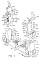
- FIGURE 1 where the subject electrical connector, designated 30 is illustrated.
- the connector in accordance with the present invention which comprises an elongated insulative housing 31 including a first housing end 32, an opposing second housing end 33 and a top side 34 which defines a board-edge slot 35 formed in the top side 34.
- Slot 35 is dimensioned to slidably receive the board-edge device (not shown) of the secondary circuit board (not shown and which forms no part of the present invention).
- the secondary circuit board lies in a substantially vertical slot plane (not shown) which intersects the housing 31 along the elongated slot 35.
- a plurality of electrically conductive terminals 36 are positioned inside slot 35 to engage respective conductive pads (not shown) disposed on the board-edge device.
- a pair of removable latches 40 and 41 which are dimensioned to engage a side edge (not shown) of the secondary circuit board such that the board is releasably secured in its operating position in the slot 35 of the electrical connector 30.
- a first support post 38 dimensioned to retain a first removable latch 40, upstands from the first housing end portion 32 of housing 31.
- a second support post 39 is dimensioned to retain a second removable latch 41 and upstands from the second housing end portion 33 of housing 31.
- the respective support posts 38 and 39 comprise a generally rectangular base portions 42 and 43 and respective backstop portians 44 and 45.
- Base portions 42 and 43 Disposed on a respective outermost base rear wall 47a, as illustrated in FIGURE 1, is a respective guidance slot 46a.
- a similar guidance slot (not visible) is formed in the opposite base near wall 47b.
- Base portions 42 and 43 further, define respective first and second vertical retaining slots 48a, 48b and 49a, 49b (not shown) positioned on respective first and second opposing base side walls 50a, 50b and 51 a, 51 b (not shown) of respective base portions 42 and 43.
- the electrical connector 30 of the present invention is mounted to the primary circuit board by respective housing mounting posts 89a and 89b extending downward from the bottom of the respective base portions 42 and 43.
- the housing mounting post 89a is illustrated which is integrally molded into the housing 31 and can extend through a correspondingly dimensioned aperture defined in a primary circuit board (not shown) to allow mounting thereon.
- first upstanding rear circuit board support 52a Extending upward from the top side 34 of the housing 31 is a first upstanding rear circuit board support 52a which includes a respective substantially vertical wall 53a disposed adjacent the board-edge slot 35.
- first board support post 52a is positioned proximate the first housing end 32, but remains positioned between the first and second support posts 38 and 39.
- the first board support post 52a is substantially rigid and inflexible in response to the forces exerted against the respective vertical wall 53a during the secondary circuit board's rotation to its operating position.
- the respective vertical wall 53a acts as a seat against which the rear face (not shown) of the secondary circuit board rests against while retained in its operating position.
- a respective alignment post 54a protruding perpendicularly outward from the respective vertical wall 53a, in a direction perpendicular to the vertical slot plane, is a respective alignment post 54a, which is aligned for engaging a correspondingly dimensioned aperture (not shown) through the secondary circuit board.
- the alignment post 54a causes the secondary circuit board to be both accurately positioned relative to the terminals 36 and to prevent improper or unintended withdrawal from the electrical connector 30.
- a respective latch front stop 55a Projecting outward from the first board support post 52a is a respective latch front stop 55a which extends in a direction toward the first support post 38. In operation, a portion of the respective first latch 40 will be contacted and prevented from extending beyond the respective latch front stop 55a. The respective latch front stop 55a prevents the respective first latch 40 from over-extending beyond the stop.
- a second board support post 52b substantially symmetrical to the first board support post 52a, is positioned proximate the second housing end 33 of housing 31.
- this mirror-image structure is disposed on the opposite end of the elongated board-edge slot 35 and includes an identical structure which performs the identical functions as the first board support post 52a.
- first and second removable latches 40 and 41 are positioned at the respective first and second housing opposing ends 32 and 33, which are, further, disposed at opposite ends of elongated board-edge slot 35. Further, the metal latches 40 and 41 are resilient. Moreover, it will be appreciated that the second latch 41 is symmetrical to, and a mirror-image of, the first latch 40. Henceforth, only the first latch 40 corresponding to the first housing end will be described in detail herein for the ease of description.
- the resilient latch 40 comprises a main body portion 56a which includes a top portion 57a, and a bottom portion 58a. Integral with the bottom portion 58a is an upstanding rectangular sleeve portion 59a which includes a substantially vertical sleeve front wall 60a, a sleeve rear wall 61 a and a respective first and second opposing sleeve side walls 62a. As shown, in this first embodiment, the bottom portion 58a of the main body 56a, is mounted atop the sleeve front wall 60a.
- the respective walls i.e., the front rear and opposing sides), collectively, define an interior portion 64a which is dimensioned to snugly receive the base portion 42 of the support post 38.
- the base portion 42 upon assembly of the electrical connector 30 of the present invention, is inserted into the interior portion 64a of sleeve portion 59a, wherein a respective latch alignment edge 65a, which protrudes into the interior portion 64a from the sleeve back wall 61 a, engages the guidance slot 46a to assure proper alignment.
- a mouth portion 66a of the guidance slot 46a is inclined outward so as to facilitate the engagement of the alignment edge 65a with the guidance slot 46a.
- Respective first and second barb members 67a and 67b are opposingly positioned and protruding into the interior portions 64a from the opposing sleeve side walls 62a and 63a. Further, the barbs 67a and 68a are positioned to correspondingly engage the respective retainment slots 48a and 49a which are constructed to reduce the resistance force of the respective first and second barbs 67a and 68a against the respective first and second base side walls 50a and 51 a during installation.
- the step portions 69a and 70a are defined by the respective base portion 42 to provide a means for securing the first latches 40 to the insulative first housing end 32.
- the respective first and second step portions 69a and 70a are positioned deeper into the base portion 42 which allows the respective barbs 67a and 68a to retainably engage therewith.
- the respective first and second barbs 67a and 68a slide along the respective retaining first and second slots 48a and 49a until they engage the respective first and second step portions 69a and 70a, thereby retaining the latch 40.
- the first latch member 40 is removably secured to the housing 31 such that the base portion 42 provides adequate lateral support to retain the secondary circuit board in its operational position in electrical connector 30.
- the first latch 40 includes a latch lug 71 a coupled to a respective first main body edge 83a which faces the rotating circuit board. As shown in FIGURE 1, the latch lug 71a a is, further, preferably positioned proximate the top portion 57a.
- the latch lug 71 a includes a camming wall 72a, which is formed to engage the first side edge (not shown) of the secondary circuit board upon rotational assembly, and respective retaining arm 73a, which is formed to removably retain the secondary circuit board in its operating position.
- the substantially planar retaining arm 73a extend outward from, and is each substantially perpendicular to, the main body portion 56a.
- the retaining arm 73a extends inwardly toward the opposing latch 41, as shown in FIGURE 1.
- the respective camming wall 72a is inclined rearwardly at an angle away from distal end of each retaining arm 73a in a direction towards the sleeve rear wall 61 a.
- This spring juncture 74a represents the intersection between the main body bottom portion 58a and the sleeve front wall 60a. Moreover, it will be appreciated that the spring juncture 74a is resilient.
- the main body portion 56a upon rotational engagement with the first board side edge of the secondary circuit board, the main body portion 56a is deflected rearward until the first board side edge clears the distal end of the retaining arm 73a, whereby the spring juncture 74a resiliently urges the main body portion 56a forward in a direction toward the latch front stop 55a. Subsequently, the planar retaining arm 73a engages a rear surface of the secondary circuit board, thereby retaining the secondary circuit board in an operating position.
- a respective latch plate 78a extends outwardly from the main body portion 56a in substantially the same direction as the retaining arm 73a. However, as shown in FIGURE 1, the latch plate 78a is coupled to a second main body edge 84a of the main body portion 56a opposite the first main body edge 83a. As best viewed in FIGURES 2A-2C, when the first latch 40 is urged backwards or forwards (i.e., when a secondary circuit board is rotatably installed or removed), the latch plate 78a slidably engages a side portion of the latch front stop 55a of the first board rear support 52a.
- This engagement provides additional guidance to the main body portion 56a during movement, as well as providing lateral stability to the latch 23
- Angularly extending away from the top portion 57a of the main body portion 56a is a cantilever lever 75a, as shown in FIGURE 1.
- the cantilever lever 75a extends angularly rearward in the direction back toward the retaining portion 44.
- a resistant and opposing bending moment (M1) shown in FIGURE 2(C), acting on the spring juncture 74a which urges the main body portion 56a back toward the latch front stop 55a.
- a backstop portion 44 is positioned atop the support post 42.
- the retaining portion 44 include support backstop wall 77a which faces toward the first latch 40.
- the support backstop wall 77a is slightly curved so that when the force (F1 a) is applied to the cantilever lever 75a and the main body portion 56a is resiliently urged respectively rearward, it will contact substantially all the support backstop wall 77a.
- the curved backstop wall 77a fits the motion orbit of the main body portion 56 when the same is urged rearward. Accordingly, the backstop wall 77a prevents the main body portion 56a from being over-extended in the rearward direction. This greatly diminishes permanent deformation at the spring juncture 74a.
- each of the next alternative embodiments will only be referenced with respect to one, housing end, 32 or 33, and the respective corresponding latch, 40 or 41, for the ease of description. It will be appreciated, however, that the opposing end is substantially, structurally similar, but is a mirror-image of the described component.
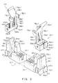
- a stress reducing arm 79a-1 extends downward from top portion 57a-1 of the main body portion 56a-1. As will be described in greater detail below, the stress reducing arm 79a-1 reduces the bending stress concentrated at spring juncture 74a-1.
- the respective moment reducing arms 79a-1 and 79b-1 preferably are centrally positioned and extend substantially the vertical length of the respective main body portions 56a-1 and 56b-1.
- the stress reducing arm 79a-1 is angled rearwardly in the direction toward sleeve rear wall 61a-1.
- the main body portion 56a-1 defines an arm slot 80a-1 in which the stress reducing arm 79a-1 is free to extend through during deflection of the main body 56a-1.
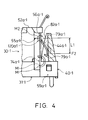
- the support post 42-1 defines an upstanding channel 81 a-1 including a rear retaining wall 82a-1, as shown in FIGURES 3, 4 and 5A-5C.
- the stress reducing arm 79a-1 is illustrated in phantom lines to represent its relaxed state.
- the secondary moment about the reducing arm juncture 120a-1 is in the direction opposite the primary bending moment (M3) created by the resiliency of the spring juncture 74a-1 itself.
- M3 primary bending moment
- the collective moment (M4) about spring juncture 74a-1 still retainably urges the respective main body portion 56a-1 against the latch front stop 55a.
- the force which the main body portion 56a-1 abuts the respective latch front stop 55a is slightly smaller than if the respective stress reducing am 79a-1 were not present.
- the stress concentration at the spring juncture 74a-1 is reduced and redistributed to the stress concentration created at the reducing arm juncture 120a-1 by the secondary bending moment M2). This reduces stress fracturing and metal fatigue at the spring juncture 120a-1.
- two respective stress reducing arms may be provided which extend downward from the respective top portion 57a-1 of the main body 56a-1.
- FIGURE 22 represents still another alternative latch embodiment 40-10 which will be discussed below.
- the main body portion 56a-10 is centrally positioned while the respective reducing arms 79a-10 are positioned on opposing adjacent ends of the main body portion 56a-10.
- the primary bending moment will now be created by the dual stress reducing arms 79a-10 while the secondary bending moment will be created by the main body portion 56a-10.
- the retaining rear wall 82a-10 (not shown) will similarly oppose the respective dual stress reducing arms 79a-10, but will be positioned on the outer opposing edges of retaining portion 44-10 to allow engagement thereof.
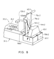
- FIGURES 6-8 another embodiment of the reduced stress arm 79a-2 is illustrated.
- the arm 79a-2 contacts the retaining wall 82a-2 at a respective arm distal end 87a-2, as opposed to the mid-portion of the arm 79a-1, as occurs in the previous embodiment.
- the retaining wall 82a-1 protrudes outward toward the latch 40-2 from the retaining portion 44-2.
- a retaining step 85a-2 upstands from the base portion 42-2, and further, is adjacent to the protruding retaining wall 82a-2.
- FIGURE 9 represents still another embodiment of the removable latches 40-3 and 41-3 of the present invention.
- the respective removable latches 40-3 and 41-3 which include the respective sleeve portion 59a-3 and 59b-3, also include a primary circuit board mounting means 88a-3 and 88b-3 extending vertically downward therefrom.
- mounting means 88a-3 provide a means for releasably mounting the electrical connector 30-3 of the present invention to the primary circuit board (not shown). It will be appreciated that the mounting engaging means 88a-3 coupled to the latch 40-3 is appropriately positioned (discussed below) to replace the housing mounting post of the previous embodiments.
- the electrical connector 30-3 may be more easily removed from the primary circuit board when desired.
- the respective sleeve portion 59a-3 is operative to securely engage the removable latch 40-3 to the connector housing 31-3, while the primary circuit board mounting means 88a-3 is operative to securely retain the first latch 40-3 and the entire housing 31-3 to the primary circuit board.
- the board mounting means 88a-3 preferably comprises a downward extending, substantially planar engaging arm 92a-3 which includes a pair of aperture engaging fingers 90a-3.
- the arm 92a-3 is coupled to the latch alignment edge 65a-3.
- the latch alignment edge 65a-3 protrudes further into the sleeve interior 64a-3 so that the respective mounting means 88a-3 may be affixed thereon.
- the support post 38-3 is modified to allow the mounting means 88a-3 to be positioned therethrough.
- a planar engaging means slot 93a-3 extends substantially through the support post 38-3 from the outermost rear wall 47a-3 in a direction inward toward the elongated board edge slot 35-3 and substantially parallel to the vertical slot plane. It will be appreciated that upon assembly of the latch 40-3 onto the support posts 38-3, the mounting means 88a-3 and the latch alignment edge 65a-3 will slidingly engage the engaging means slot 93a-3 to allow the base portion 42-3 to engage the sleeve portion 59a-3 of the latch 40-3. Thus, the aperture engaging fingers 90a-3 will protrude from the bottom of the housing 30-3 in a manner and position substantially similar to the housing mounting posts of the previous embodiments.
- Each finger 90a-3 is inclined outward from its respective distal end such that an inward collapsing of the fingers 90a-3 is generated in response to forces exerted on the fingers as they are urged into an appropriately dimensioned mounting aperture (not shown) on the primary circuit board.
- Each respective finger 90a-3 further, includes locking surfaces 91 a-3 for engaging a second surface of the primary circuit board opposite a first surface thereof on which the electrical connector 30-3 is positioned.
- the locking surfaces 91 a-3 engage the second surface of the primary circuit board to releasably retain the electrical connector 30-3 to the primary circuit board.
- each respective mounting arm 92a-3 and 92b-3 is determined by the thickness of the primary circuit board. Thus, different board thicknesses can be accommodated by selecting the proper arm length.
- FIGURE 10 Another embodiment employing the sleeve portion mechanism of attachment to the housing end is illustrated in FIGURE 10.
- an alternative retainment mechanism is exhibited in which the respective sleeve portion 59b-4 of the latch 41-4 is removably mounted to, and aligned with, the housing 31-4 by the upper retaining portion 45-4, as compared to the base portion 43-4 of the previous embodiments. Therefore, the retaining portion 45-4 is dimensioned to insert into the respective sleeve portion 59b-4.
- the respective first and second retainment slots 67b-4 and 68b-4, as well as the respective step portions 69b-4 and 70b-4 (not shown) are also defined by the upper retaining portion 45-4.
- a first and a second vertical guidance slots 101 b-4 and 102b-4 are defined by the upper retaining portion 45-4 disposed on a substantially vertical retaining portion rear wall 103b-4.
- the respective sleeve portion 59b-4 of the latch 41-4 remains coupled the bottom portion 58b-4 of the main body 56b-4.
- the sleeve portion 59b-4 extends upward from the bottom portion 58b-4, as opposed to extending downward, such that a first and a second sleeve gap 104b-4 and 105b-4 is formed between the edge of the respective first and second opposing sleeve side walls 62b-4 and 62b-4 and the respective first and second side edges 83b-4 and 84b-4 of the main body portion 56b-4.
- sleeve gaps 104a-4 and 105b-4 permit the main body portion 56b-4 to move more freely into and out of the sleeve interior 64b-4.
- a first and second substantially parallel latch alignment edge 111 b-4 and 112b-4 extend into the sleeve interior portion 64b-4 from the sleeve rear wall 61 b-4.
- the respective step portions 69b-4 and 70b-4 do not need to be positioned deeper into the backstop portion 45-4, as with the previous embodiments, in order to allow the respective barbs 67b-4 and 68b-4 to retainably engage therewith.
- the respective retaining slots 48b-4 and 49b-4 are inclined outward toward the respective sides of the backstop portion 45-4 to form the respective retaining step portions 69b-4 and 70b-4.
- the respective barbs 67b-4 and 68b-4 slide along the respective retaining slots 48b-4 and 49b-4 until they engage the respective step portions 69b-4 and 70b-4, thereby releasably retaining the latch 41-4 to the housing 31-4.
- the latch member 41-4 is removably secured to the housing 31-4 such that the retaining portion 4-43 provides adequate lateral support to retain the secondary circuit board in its operational position in electrical connector 30-4.
- the next electrical connector represents the preferred mechanism of attachment to the insulative housing 31-5, as shown in FIGURE 11.
- the main body bottom portion 58b-5 of the latch 41-5 is coupled to a mounting platform 94b-5 which replaces the sleeve portions of the previous embodiments.
- the mounting platform 94b-4 is comprised of a substantially rectangular upper support plate 106b-4 which extends perpendicularly rearward from the main body bottom portion 58b-5 in the direction substantially parallel to the housing top side 34-5 in which it will supportably mate.
- Respective first and second mounting fingers 96b-5 and 97b-5 extend perpendicularly downward from the opposing side ends of the rectangular support plate 106b-5 in a direction substantially parallel to the respective first and second opposing base side walls 50b-5 and 51 b-5 of the base portion 43-5. It will be appreciated that the first and second downwardly bent mounting fingers 96b-5 and 97b-5 are laterally spaced apart by a distance substantially equal to the cross-sectional width of the housing connector top side 34-5. The properly spaced apart first and second mounting fingers 96b-5 and 97b-5 assure that the mounting platform 94b-4 is snugly supported by the base portion 43-5 of the respective second support post 39-5, as illustrated in FIGURE 12.
- the base portion 43-5 of the respective support post 39-5 defines respective first and second alignment finger grooves 122b-5 and 124b-5 disposed on the respective first and second opposing base side walls 50b-5 and 51 b-55.
- These respective alignment finger grooves 122b-5 and 124b-5 are dimensioned to flushly receive the respective first and second mounting fingers 96b-5 and 97b-5 such that the respective fingers are seated an aligned.
- this helps align the respective latch 41 upon mounting to the housing 31-5 (discussed henceforth) and, further, provide lateral support when the secondary circuit board is mounted.
- first and second mounting finger slots 98b-5 and 99b-5 are also disposed on the respective first and second opposing base side walls 50b-5 and 51 b-55.
- These respective finger slots 98b-5 and 99b-5 are dimensioned to accept the respective first and second mounting fingers 96b-5 and 97b-5, as shown in FIGURES 12 and 13.
- Reminiscent of a staple hence its name, the respective distal ends of the mounting fingers 96b-5 and 97b-5 are bent inward towards the respective first and second mounting finger slots 98b-5 and 99b-5, shown in the phantom lines in FIGURE 12.
- This staple mounting mechanism simplifies installation and enhances lateral support to the latch 41-5 when the respective distal ends of the mounting fingers 96b-5 and 97b-5 engage the respective finger slots 98b-5 and 99b-5. Accordingly, the respective latch 41-5 is securely mounted to the second housing end 33-5.
- the respective upstanding backstop portion 45-5 provides a rear latch backstop wall 77b-5 much like the previous embodiments.
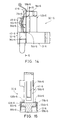
- FIGURES 14 and 15 represent the preferred previous staple mounting mechanism embodiment which includes a stress reducing arm 79b-6.
- the stress reducing arm 79b-6 when engaged with the retaining wall 82b-6 of the upstanding retaining portion 45-6, decreases the stress concentration at the spring juncture 74b-6.
- This embodiment includes a latch front stop 55b-6 protruding toward the respective latch 41-6 from the rear circuit board support 52b-6 to prevent over-extension.
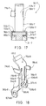
- FIGURES 16 and 17 an alternative main body portion 56b-7 is illustrated coupled to the mounting platform 94b-7.
- the main body portion 56b-7 of this embodiment is substantially curved, rather than planar.
- the actual length of the main body portion 56b-7 is longer than the previous embodiments because of its curved positioning.
- This increased length enhances the overall flexibility of the main body portion 56b-7 which reduces stress concentration at spring juncture 74b-7.
- this curvature and increased flexibility distributes the bending stress throughout the main body portion 56b-7 when the same is deflected rearward during installation or removal of the secondary circuit board.
- the mounting platform 94b-7 is mounted forward of the main body bottom side 58b-7, as opposed to being mounted rearward. Moreover, the bottom portion 58b-7 of the main body portion 56b-7 extends from the rectangular mounting support plate 106b-7 in a direction substantially parallel to the plate. In the previous latch embodiments, the main body portion extends substantially perpendicular therefrom. Thus, as the main body portion 56b-7 is displaced reward, the stress acting on the main body portion 56b-7 is absorbed all along the curvature. Accordingly, the bending stress is not narrowly concentrated at the spring juncture 74b-7 because it is distributed throughout the curvature of the main body portion 56b-7.
- the upper portion 57b-7 of the main body portion 56ab-7 remains substantially planar to promote planar engagement with the front latch stop 55b-7. Further, the backstop portion 45-7 which prevents latch over-extension is simplified and substantially planar.
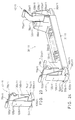
- FIG. 18-20 Another alternative mounting mechanism mounting the removable latches 40-8 (not shown) and 41-8 to the housing 31-8 is illustrated in the connector assembly 30-8 of FIGURES 18-20. Similar to the staple mounting mechanism of the previous embodiment, this mounting mechanism comprises a mounting platform 94b-8 which includes a rectangular support plate 106b-8 extending perpendicularly rearward from the main body bottom portion 58b-8. Again, respective first and second mounting fingers 96b-8 and 97b-8 extend perpendicularly downward from the opposing side ends of the rectangular support plate 106b-8.
- first and second mounting fingers 96b-8 and 97b-8 are not bent inward, respectively, toward one another. Rather, retainment is provided by first and second inwardly inclined barbs 107b-8 and 108b-8 which are defined by the respective first and second mounting fingers 96b-8 and 97b-8.
- These respective barbs 107b-8 and 108b-8 represent an uncomplicated mechanism for mounting the respective latch 41-8 to the respective second housing end 33-8.
- the respective base portion 43-8 defines a respective first and second barb step 109b-8 and 110b-8 positioned oppositely on the respective first and second opposing base side walls 50b-8 and 51 b-8.
- the first and second barb steps 109b-8 and 110b-8 are appropriately aligned and dimensioned to engage the corresponding first and second mounting finger barbs 107b-8 and 108b-8.
- the respective latch 41-8 will be securely mounted to the respective housing end 33-8.
- FIGURE 21 represents yet another removable latch alternative embodiment mounting mechanism of the present invention.
- a dual post receiving mounting mechanism 113b-9 which comprises respective first and second upstanding cylindrical sleeves 114b-9 and 115b-9 disposed adjacent the opposing first and second main body edges 83b-9 and 84b-9, respectively.
- the first and second cylindrical sleeves 114b-9 and 115b-9 are coupled together at the opposing longitudinal edges of a substantially vertical connecting plate 116b-9 positioned therebetween.
- a top edge of the vertical connecting plate 116b-9 is coupled to the main body bottom portion 58b-9 which defines the respective spring juncture 74b-9.
- the respective first and second cylindrical sleeves 114b-9 and 115b-9 are dimensioned to receive corresponding, respective first and second support posts (not shown) upstanding from the housing top side (not shown) of the respective second housing end (not shown). These respective first and second support posts are preferably inclined outward from the respective distal ends such that the respective first and second cylindrical sleeves 114b-9 and 115b-9 may be snugly mounted thereon. Positioned in the respective interior portions 116b-9 and 117b-9 of the respective first and second cylindrical sleeves 114b-9 and 115b-9 are retaining barbs (not shown) which releasably retain the latch 41-9 onto the respective support posts thereon. Moreover, these respective support posts provide lateral stability to the respective latches 40-9 (not shown) and 41-9 so that the secondary circuit board may be securely mounted in its operating position.
- this alternative latch 40-10 illustrates the dual post receiving mounting mechanism 113b-10 coupled to the main body portion 56b-10 including dual stress reducing arms 79b-10. Both of these components have been previously discussed in detail, and, thus, will not be repeated here.
- the latch 41-11 includes a resilient backstop portion 126b-11 integrally coupled to the mounting platform 94b-11. Extending upward from the rear end of rectangular support plate 106b-11 is an upstanding resilient backstop support 128b-11. This support 128b-11 is substantially perpendicular to rectangular support plate 106b-11 and is mounted to the end opposite, but substantially parallel to, the main body portion 56b-11. Coupled to the upper distal end of resilient backstop support 128b-11 is a resilient backstop plate 130b-11 inclined downward toward the spring juncture 74b-11. The resilient backstop spring juncture 132b-11 between the upper distal end of resilient backstop support 128b-11 and the upper distal end of the resilient backstop plate 130b-11 form a resilient spring.
- the main body portion 56b-11 may be displaced reward until it engages the resilient backstop portion 128b-11.
- the main body portion 56b-11 substantially contacts the resilient backstop plate 130b-11 which tensions the resilient backstop spring juncture 132b-11. This acts to urge the main body portion 56b-11 forward toward the respective board support post 52b-11, as shown in FIGURE 24.
- the resilient backstop portion 128b-11 provide a backstop to prevent over-extension of the main body portion 56b-11, it also provides a backstop spring juncture 132b-11 which, together with the spring juncture 74b-11, urge main body portion 56b-11 forward.
- FIGURE 24 illustrates the connector assembly 30-11 with the first and second latches 40-11 and 41-11 mounted to the housing 31-11.
- the respective first and second mounting fingers 96b-11 and 97b-11 are wider than the previous staple mounting embodiments in order to provide better lateral support.
- an alternative mounting platform 94b-12 is coupled to the latch 41-12 including the resilient backstop portion 126b-12.
- the mounting platform 94b-12 does not include mounting fingers coupled to the ends of the rectancular support plate 106b-12. Rather, a first and a second support plate barb 134b-12 and 136b-12 (not shown), respectively, are provided to retainably mount the latch 41-12 to the connector housing 31-12.
- the respective second housing end 33-12 defines a rectangular support plate mounting slot 138b-12 in which the respective rectangular support plate 106b-12 slidably engages. Respective first and second support plate barbs 134b-12 and 136b-12 engage the inner walls of the mounting slot 138b-12 to securely retain the latch 41-12 to the housing 31-12.
Landscapes
- Details Of Connecting Devices For Male And Female Coupling (AREA)
- Coupling Device And Connection With Printed Circuit (AREA)
Applications Claiming Priority (2)
| Application Number | Priority Date | Filing Date | Title |
|---|---|---|---|
| US07/745,609 US5286217A (en) | 1991-08-15 | 1991-08-15 | Electrical connector with improved latch mechanism |
| US745609 | 1991-08-15 |
Publications (3)
| Publication Number | Publication Date |
|---|---|
| EP0528259A2 true EP0528259A2 (de) | 1993-02-24 |
| EP0528259A3 EP0528259A3 (en) | 1993-08-11 |
| EP0528259B1 EP0528259B1 (de) | 1996-07-17 |
Family
ID=24997460
Family Applications (1)
| Application Number | Title | Priority Date | Filing Date |
|---|---|---|---|
| EP92113287A Expired - Lifetime EP0528259B1 (de) | 1991-08-15 | 1992-08-04 | Elektrischer Verbinder mit verbessertem Verriegelungsmechanismus |
Country Status (4)
| Country | Link |
|---|---|
| US (2) | US5286217A (de) |
| EP (1) | EP0528259B1 (de) |
| CN (1) | CN2173465Y (de) |
| DE (1) | DE69212253D1 (de) |
Cited By (10)
| Publication number | Priority date | Publication date | Assignee | Title |
|---|---|---|---|---|
| GB2261559B (en) * | 1991-11-14 | 1995-08-23 | Du Pont | Electrical connector |
| WO1997003484A1 (en) * | 1995-07-11 | 1997-01-30 | The Whitaker Corporation | Card edge connector and card edge connector fastening device used in the same |
| EP0704112A4 (de) * | 1993-06-03 | 1998-05-27 | Berg Electronics Mfg | Elektrischer verbinder |
| EP0714563A4 (de) * | 1993-08-19 | 1998-06-03 | Berg Electronics Mfg | Verfahren zur herstellung von polyhydroxybutyrat und verwandten polyhydroxyalkanoaten in den plastiden höherer pflanzen |
| EP0878035A4 (de) * | 1995-07-06 | 1998-11-18 | ||
| US5938463A (en) * | 1995-07-06 | 1999-08-17 | Berg Technology, Inc. | Socket for printed circuit boards |
| KR100383202B1 (ko) * | 1998-01-06 | 2003-07-07 | 커넥터 시스템즈 테크놀로지 엔.브이. | 인쇄회로기판용소켓 |
| KR100383209B1 (ko) * | 1994-12-20 | 2003-07-18 | 커넥터 시스템즈 테크놀로지 엔.브이. | 인쇄회로기판용소켓 |
| EP1801921A3 (de) * | 2005-12-21 | 2010-09-08 | Harting Electronics GmbH & Co. KG | Vorrichtung für eine präzise Kontaktführung bei Leiterplattensteckverbindungen |
| EP1981322A3 (de) * | 2007-04-12 | 2011-02-23 | Funai Electric Co., Ltd. | Stehtafelbefestigungsstruktur und Fernsehempfangsgerät |
Families Citing this family (34)
| Publication number | Priority date | Publication date | Assignee | Title |
|---|---|---|---|---|
| DE59309954D1 (de) * | 1992-12-21 | 2000-03-16 | Balzers Hochvakuum | Optisches Bauelement, Verfahren zur Herstellung einer Schicht, Schicht bzw. Schichtsystem und Verwendung des Bauelementes |
| US5504397A (en) * | 1994-09-02 | 1996-04-02 | Chien; Tseng-Lu | Neon lamp assembly |
| JP3015081U (ja) * | 1995-01-20 | 1995-08-29 | モレックス インコーポレーテッド | 印刷回路基板状体接続用電気コネクタ |
| US5569043A (en) * | 1995-08-04 | 1996-10-29 | Liu; Kai-Mai | Latch mechanism for use in an electric connector |
| US6054990A (en) * | 1996-07-05 | 2000-04-25 | Tran; Bao Q. | Computer system with handwriting annotation |
| US5766031A (en) * | 1996-12-11 | 1998-06-16 | Yeh; Te-Hsin | Electrical connector with fasteners |
| US6027357A (en) * | 1996-12-13 | 2000-02-22 | The Whitaker Corporation | Electrical connector having metal latch |
| CN1082730C (zh) * | 1997-03-06 | 2002-04-10 | 鸿海精密工业股份有限公司 | 电路板辅助定位装置 |
| CN1085423C (zh) * | 1997-03-12 | 2002-05-22 | 鸿海精密工业股份有限公司 | 电连接器扣件 |
| CN1085424C (zh) * | 1997-03-19 | 2002-05-22 | 鸿海精密工业股份有限公司 | 电连接器 |
| CN1080008C (zh) * | 1997-03-19 | 2002-02-27 | 鸿海精密工业股份有限公司 | 电连接器 |
| TW376213U (en) * | 1997-08-30 | 1999-12-01 | Hon Hai Prec Ind Co Ltd | Fixing apparatus of folding type |
| JP3883151B2 (ja) | 1998-01-29 | 2007-02-21 | タイコエレクトロニクスアンプ株式会社 | ラッチ付コネクタ |
| JP2000208183A (ja) | 1998-07-27 | 2000-07-28 | Tyco Electronics Amp Kk | カ―ドエッジコネクタ |
| US6585534B2 (en) | 1998-08-20 | 2003-07-01 | Intel Corporation | Retention mechanism for an electrical assembly |
| US6159031A (en) * | 1999-06-07 | 2000-12-12 | Intel Corporation | Retention mechanism that can be used with different electronic assemblies |
| US6370036B1 (en) | 1999-06-10 | 2002-04-09 | Micron Technology, Inc. | Apparatus and method for retaining a circuit board |
| US6361343B1 (en) * | 1999-09-21 | 2002-03-26 | Intel Corporation | Circuit card retention mechanism |
| US6353541B1 (en) | 1999-10-20 | 2002-03-05 | Micron Pc, Llc | Processor and circuit board retaining apparatus and method |
| AU2002952691A0 (en) * | 2002-11-15 | 2002-11-28 | Sunshine Heart Company Pty Ltd | Heart assist device utilising aortic deformation |
| US7309248B2 (en) * | 2005-06-27 | 2007-12-18 | Yazaki Corporation | Connector fixing structure for fixing a connector to a board |
| TW200725993A (en) * | 2005-12-30 | 2007-07-01 | Top Yang Technology Entpr Co | Electric connector |
| TWI359299B (en) * | 2007-01-11 | 2012-03-01 | Qisda Corp | Fixing module capable of fastening a board and fix |
| US7391619B1 (en) * | 2007-09-14 | 2008-06-24 | T-Conn Precision Corp. | Latch for interface card |
| US20090075511A1 (en) * | 2007-09-17 | 2009-03-19 | Samtec Inc. | Socket and electrical assembly including the socket |
| JP2010225466A (ja) * | 2009-03-24 | 2010-10-07 | Fujitsu Component Ltd | 基板接続用コネクタ |
| US20110130042A1 (en) * | 2009-11-27 | 2011-06-02 | Wan-Tien Chen | Mini pci express connector |
| CN102110921B (zh) * | 2009-12-29 | 2014-01-15 | 鸿富锦精密工业(深圳)有限公司 | 连接器组合 |
| JP5099387B2 (ja) * | 2010-09-09 | 2012-12-19 | 第一精工株式会社 | コネクタ装置 |
| JP5195863B2 (ja) * | 2010-10-12 | 2013-05-15 | 第一精工株式会社 | 電気コネクタ |
| TWM451794U (zh) * | 2012-11-26 | 2013-04-21 | Wistron Corp | 用來固定電子裝置之介面卡之固定機構與電子裝置 |
| CN110061376B (zh) * | 2019-04-24 | 2024-02-23 | 富士康(昆山)电脑接插件有限公司 | 卡缘连接器 |
| CN211428391U (zh) * | 2019-11-20 | 2020-09-04 | 富士康(昆山)电脑接插件有限公司 | 卡缘连接器 |
| US11831101B2 (en) * | 2022-01-05 | 2023-11-28 | Dell Products L.P. | Fine alignment adapter for a connector |
Family Cites Families (14)
| Publication number | Priority date | Publication date | Assignee | Title |
|---|---|---|---|---|
| US4850892A (en) * | 1985-12-16 | 1989-07-25 | Wang Laboratories, Inc. | Connecting apparatus for electrically connecting memory modules to a printed circuit board |
| US4737120A (en) * | 1986-11-12 | 1988-04-12 | Amp Incorporated | Electrical connector with low insertion force and overstress protection |
| US4713013A (en) * | 1987-01-30 | 1987-12-15 | Molex Incorporated | Compliant high density edge card connector with contact locating features |
| JPH01175180A (ja) * | 1987-12-28 | 1989-07-11 | Yamaichi Electric Mfg Co Ltd | 配線基板用コネクタ |
| JPH0252278U (de) * | 1988-10-05 | 1990-04-16 | ||
| US4986765A (en) * | 1989-02-21 | 1991-01-22 | Amp Incorporated | Insertable latch means for use in an electrical connector |
| JP2704553B2 (ja) * | 1989-09-22 | 1998-01-26 | 日本エー・エム・ピー株式会社 | エッジコネクタおよびコネクタ用基板係止装置 |
| US5011424A (en) * | 1989-11-01 | 1991-04-30 | Amp Incorporated | Latch mechanism for electrical connector |
| US4995825A (en) * | 1990-03-19 | 1991-02-26 | Amp Incorporated | Electronic module socket with resilient latch |
| US5013257A (en) * | 1990-06-27 | 1991-05-07 | Amp Incorporated | Circuit board connector having improved latching system |
| US5094624A (en) * | 1990-12-18 | 1992-03-10 | Molex Incorporated | Metal latch for SIMM socket |
| US5112242A (en) * | 1990-11-20 | 1992-05-12 | Foxconn International, Inc. | Durable latch for memory module board |
| US5174780A (en) * | 1991-03-29 | 1992-12-29 | Yang Lee Su Lan | Slant socket for memory module |
| US5244403A (en) * | 1991-04-10 | 1993-09-14 | Augat Inc. | Electronic component socket with external latch |
-
1991
- 1991-08-15 US US07/745,609 patent/US5286217A/en not_active Expired - Fee Related
-
1992
- 1992-08-04 EP EP92113287A patent/EP0528259B1/de not_active Expired - Lifetime
- 1992-08-04 DE DE69212253T patent/DE69212253D1/de not_active Expired - Lifetime
- 1992-08-13 CN CN92230643U patent/CN2173465Y/zh not_active Expired - Lifetime
-
1993
- 1993-09-16 US US08/123,241 patent/US5372518A/en not_active Expired - Fee Related
Cited By (11)
| Publication number | Priority date | Publication date | Assignee | Title |
|---|---|---|---|---|
| GB2261559B (en) * | 1991-11-14 | 1995-08-23 | Du Pont | Electrical connector |
| EP0704112A4 (de) * | 1993-06-03 | 1998-05-27 | Berg Electronics Mfg | Elektrischer verbinder |
| KR100338619B1 (ko) * | 1993-06-03 | 2002-11-27 | 커넥터 시스템즈 테크놀로지 엔.브이. | 전기커넥터 |
| EP0714563A4 (de) * | 1993-08-19 | 1998-06-03 | Berg Electronics Mfg | Verfahren zur herstellung von polyhydroxybutyrat und verwandten polyhydroxyalkanoaten in den plastiden höherer pflanzen |
| KR100383209B1 (ko) * | 1994-12-20 | 2003-07-18 | 커넥터 시스템즈 테크놀로지 엔.브이. | 인쇄회로기판용소켓 |
| EP0878035A4 (de) * | 1995-07-06 | 1998-11-18 | ||
| US5938463A (en) * | 1995-07-06 | 1999-08-17 | Berg Technology, Inc. | Socket for printed circuit boards |
| WO1997003484A1 (en) * | 1995-07-11 | 1997-01-30 | The Whitaker Corporation | Card edge connector and card edge connector fastening device used in the same |
| KR100383202B1 (ko) * | 1998-01-06 | 2003-07-07 | 커넥터 시스템즈 테크놀로지 엔.브이. | 인쇄회로기판용소켓 |
| EP1801921A3 (de) * | 2005-12-21 | 2010-09-08 | Harting Electronics GmbH & Co. KG | Vorrichtung für eine präzise Kontaktführung bei Leiterplattensteckverbindungen |
| EP1981322A3 (de) * | 2007-04-12 | 2011-02-23 | Funai Electric Co., Ltd. | Stehtafelbefestigungsstruktur und Fernsehempfangsgerät |
Also Published As
| Publication number | Publication date |
|---|---|
| US5372518A (en) | 1994-12-13 |
| EP0528259A3 (en) | 1993-08-11 |
| EP0528259B1 (de) | 1996-07-17 |
| US5286217A (en) | 1994-02-15 |
| DE69212253D1 (de) | 1996-08-22 |
| CN2173465Y (zh) | 1994-08-03 |
Similar Documents
| Publication | Publication Date | Title |
|---|---|---|
| US5286217A (en) | Electrical connector with improved latch mechanism | |
| US7074067B2 (en) | Card edge connector with latching arms | |
| CA1230939A (en) | Circuit board assembly for accurate insertion | |
| US5244412A (en) | Electrical device for surface mounting on a circuit board and mounting component thereof | |
| KR100347041B1 (ko) | 정보기기용 메모리카드 커넥터 | |
| US5184961A (en) | Modular connector frame | |
| JP2855197B2 (ja) | 電気コネクタ | |
| US5244403A (en) | Electronic component socket with external latch | |
| EP0702432A1 (de) | Stecker für Leiterplatte | |
| JPH0613117A (ja) | 電気コネクタ | |
| US20050054242A1 (en) | Circuit board mounted electrical connector | |
| JP2685287B2 (ja) | 多接点組立体および可撓接点部材 | |
| US20070026717A1 (en) | Ic socket | |
| US6361374B1 (en) | Connector module retainer especially suitable for wafer connectors and connector assembly utilizing same | |
| EP0851535A2 (de) | Verbinderteile | |
| JPH06208874A (ja) | カードリーダ用電気コネクタ | |
| US6183270B1 (en) | Electrical connector | |
| US6312288B1 (en) | Low profile combination switch and connector assembly | |
| JPH10106674A (ja) | カードコネクタ | |
| US6116957A (en) | Electrical connector for interconnecting two circuit boards | |
| KR960004806B1 (ko) | 전기 접속기 | |
| US6012954A (en) | Electrical connector | |
| US5860825A (en) | Socket for printed circuit board | |
| US5468160A (en) | Mounting bracket for an electrical connector | |
| US7604509B2 (en) | Card connector |
Legal Events
| Date | Code | Title | Description |
|---|---|---|---|
| PUAI | Public reference made under article 153(3) epc to a published international application that has entered the european phase |
Free format text: ORIGINAL CODE: 0009012 |
|
| 17P | Request for examination filed |
Effective date: 19920828 |
|
| AK | Designated contracting states |
Kind code of ref document: A2 Designated state(s): DE FR GB |
|
| PUAL | Search report despatched |
Free format text: ORIGINAL CODE: 0009013 |
|
| AK | Designated contracting states |
Kind code of ref document: A3 Designated state(s): DE FR GB |
|
| 17Q | First examination report despatched |
Effective date: 19940624 |
|
| GRAH | Despatch of communication of intention to grant a patent |
Free format text: ORIGINAL CODE: EPIDOS IGRA |
|
| GRAH | Despatch of communication of intention to grant a patent |
Free format text: ORIGINAL CODE: EPIDOS IGRA |
|
| GRAA | (expected) grant |
Free format text: ORIGINAL CODE: 0009210 |
|
| AK | Designated contracting states |
Kind code of ref document: B1 Designated state(s): DE FR GB |
|
| PG25 | Lapsed in a contracting state [announced via postgrant information from national office to epo] |
Ref country code: FR Effective date: 19960717 |
|
| REF | Corresponds to: |
Ref document number: 69212253 Country of ref document: DE Date of ref document: 19960822 |
|
| PG25 | Lapsed in a contracting state [announced via postgrant information from national office to epo] |
Ref country code: GB Effective date: 19961017 |
|
| PG25 | Lapsed in a contracting state [announced via postgrant information from national office to epo] |
Ref country code: DE Effective date: 19961018 |
|
| EN | Fr: translation not filed | ||
| PLBE | No opposition filed within time limit |
Free format text: ORIGINAL CODE: 0009261 |
|
| GBPC | Gb: european patent ceased through non-payment of renewal fee |
Effective date: 19961017 |
|
| 26N | No opposition filed |