EP0526684A2 - Lithium-Jod-Batterie - Google Patents
Lithium-Jod-Batterie Download PDFInfo
- Publication number
- EP0526684A2 EP0526684A2 EP92100730A EP92100730A EP0526684A2 EP 0526684 A2 EP0526684 A2 EP 0526684A2 EP 92100730 A EP92100730 A EP 92100730A EP 92100730 A EP92100730 A EP 92100730A EP 0526684 A2 EP0526684 A2 EP 0526684A2
- Authority
- EP
- European Patent Office
- Prior art keywords
- battery
- lithium
- iodine
- battery housing
- housing
- Prior art date
- Legal status (The legal status is an assumption and is not a legal conclusion. Google has not performed a legal analysis and makes no representation as to the accuracy of the status listed.)
- Ceased
Links
Images
Classifications
-
- G—PHYSICS
- G04—HOROLOGY
- G04C—ELECTROMECHANICAL CLOCKS OR WATCHES
- G04C10/00—Arrangements of electric power supplies in time-pieces
-
- H—ELECTRICITY
- H01—ELECTRIC ELEMENTS
- H01M—PROCESSES OR MEANS, e.g. BATTERIES, FOR THE DIRECT CONVERSION OF CHEMICAL ENERGY INTO ELECTRICAL ENERGY
- H01M50/00—Constructional details or processes of manufacture of the non-active parts of electrochemical cells other than fuel cells, e.g. hybrid cells
- H01M50/10—Primary casings; Jackets or wrappings
- H01M50/172—Arrangements of electric connectors penetrating the casing
- H01M50/174—Arrangements of electric connectors penetrating the casing adapted for the shape of the cells
-
- H—ELECTRICITY
- H01—ELECTRIC ELEMENTS
- H01R—ELECTRICALLY-CONDUCTIVE CONNECTIONS; STRUCTURAL ASSOCIATIONS OF A PLURALITY OF MUTUALLY-INSULATED ELECTRICAL CONNECTING ELEMENTS; COUPLING DEVICES; CURRENT COLLECTORS
- H01R4/00—Electrically-conductive connections between two or more conductive members in direct contact, i.e. touching one another; Means for effecting or maintaining such contact; Electrically-conductive connections having two or more spaced connecting locations for conductors and using contact members penetrating insulation
- H01R4/02—Soldered or welded connections
-
- H—ELECTRICITY
- H01—ELECTRIC ELEMENTS
- H01R—ELECTRICALLY-CONDUCTIVE CONNECTIONS; STRUCTURAL ASSOCIATIONS OF A PLURALITY OF MUTUALLY-INSULATED ELECTRICAL CONNECTING ELEMENTS; COUPLING DEVICES; CURRENT COLLECTORS
- H01R13/00—Details of coupling devices of the kinds covered by groups H01R12/70 or H01R24/00 - H01R33/00
- H01R13/02—Contact members
- H01R13/22—Contacts for co-operating by abutting
- H01R13/24—Contacts for co-operating by abutting resilient; resiliently-mounted
-
- H—ELECTRICITY
- H01—ELECTRIC ELEMENTS
- H01R—ELECTRICALLY-CONDUCTIVE CONNECTIONS; STRUCTURAL ASSOCIATIONS OF A PLURALITY OF MUTUALLY-INSULATED ELECTRICAL CONNECTING ELEMENTS; COUPLING DEVICES; CURRENT COLLECTORS
- H01R4/00—Electrically-conductive connections between two or more conductive members in direct contact, i.e. touching one another; Means for effecting or maintaining such contact; Electrically-conductive connections having two or more spaced connecting locations for conductors and using contact members penetrating insulation
- H01R4/04—Electrically-conductive connections between two or more conductive members in direct contact, i.e. touching one another; Means for effecting or maintaining such contact; Electrically-conductive connections having two or more spaced connecting locations for conductors and using contact members penetrating insulation using electrically conductive adhesives
-
- Y—GENERAL TAGGING OF NEW TECHNOLOGICAL DEVELOPMENTS; GENERAL TAGGING OF CROSS-SECTIONAL TECHNOLOGIES SPANNING OVER SEVERAL SECTIONS OF THE IPC; TECHNICAL SUBJECTS COVERED BY FORMER USPC CROSS-REFERENCE ART COLLECTIONS [XRACs] AND DIGESTS
- Y02—TECHNOLOGIES OR APPLICATIONS FOR MITIGATION OR ADAPTATION AGAINST CLIMATE CHANGE
- Y02E—REDUCTION OF GREENHOUSE GAS [GHG] EMISSIONS, RELATED TO ENERGY GENERATION, TRANSMISSION OR DISTRIBUTION
- Y02E60/00—Enabling technologies; Technologies with a potential or indirect contribution to GHG emissions mitigation
- Y02E60/10—Energy storage using batteries
Definitions
- the invention relates to a lithium-iodine battery according to the preamble of claim 1.
- the object of the invention is to simplify the use of a lithium iodine battery for watches.
- the solution to the problem according to the invention is characterized in that the battery housing of the lithium iodine battery is designed as a watch base and can thus be connected directly to the watch housing.
- Such training is advantageous, particularly because of the longevity of the lithium iodine batteries.
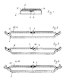
- Fig. 1 of the drawing shows schematically a battery case 2 of a lithium-iodine battery for a watch.
- the battery housing can be made of stainless steel or another material.
- An electrical conductor 4 leads out of the clockwork side - that is to say on the top side - which is fused into a glass insulator (glass bushing) 6 or comparable insulator arranged in the battery housing.
- the current draw for the clockwork can take place directly via conductor 4 or a wire contact.
- the current can also be drawn off via a metal foil 8 as a contact surface which is electrically connected to the electrical conductor 4, for example by welding, soldering or with the aid of an electrically conductive adhesive, an insulating foil 10 being arranged between the metal foil 8 and the battery housing 2, which is glued to the battery housing and the metal foil (adhesive 11).
- a spring contact (not shown) of the clockwork presses on the metal foil, so that contact is made via the contact surface and the housing closure.
- the battery housing 2 is designed as a watch bottom, as shown in FIGS. 2 to 4.
- the usual fastening options for the battery case 2 designed as a watch base with the watch case are shown for the battery case in FIGS. 2 to 4.
- FIGS. 2 and 3 show the design of the battery housing for external pressure connection and Fig. 4 for internal pressure connection.
- the battery case itself is hermetically welded.
- a metal foil 16 and in the embodiment according to FIG. 3 a central wire connection 18 serves as an electrical contact for the power supply of the clockwork.
- the glass bushing 6 is provided centrally.
- the metal foil as the contact surface enables the current to be drawn outside the center at any point on the metal foil.
- the complete watch assembly with the described battery case watch bottom does not differ fundamentally from the conventional assembly for mechanical watch movements and quartz watch movements.
- the particular advantage of the described design of the lithium-iodine battery is that the battery simultaneously takes on the function of a watch back and the function of powering the clockwork; an additional solder connection for establishing an electrical contact between the battery and the clockwork is not necessary. The contact is made simply via the contact spring of the clockwork, which is usually present.
Landscapes
- Electrochemistry (AREA)
- Power Engineering (AREA)
- Physics & Mathematics (AREA)
- General Physics & Mathematics (AREA)
- Chemical & Material Sciences (AREA)
- Chemical Kinetics & Catalysis (AREA)
- Engineering & Computer Science (AREA)
- General Chemical & Material Sciences (AREA)
- Battery Mounting, Suspending (AREA)
- Electromechanical Clocks (AREA)
- Primary Cells (AREA)
- Connection Of Batteries Or Terminals (AREA)
- Electric Clocks (AREA)
Abstract
Description
- Die Erfindung betrifft eine Lithium-Jod-Batterie gemäß Oberbegriff des Anspruchs 1.
- Aufgabe der Erfindung ist es, die Verwendung einer Lithium-Jod-Batterie für Uhren zu vereinfachen.
- Diese Aufgabe wird durch die Ausbildung gemäß Kennzeichen des Anspruchs 1 gelöst.
- Die erfindungsgemäße Aufgabenlösung zeichnet sich dadurch aus, daß das Batteriegehäuse der Lithium-Jod-Batterie als Uhrenboden ausgebildet ist und somit unmittelbar mit dem Uhrengehäuse verbunden werden kann. Eine solche Ausbildung ist vorteilhaft, insbesondere wegen der Langlebigkeit der Lithium-Jod-Batterien.
- Vorteilhafte und zweckmäßige Weiterbildungen der erfindugsgemäßen Aufgabenlösung sind in den Unteransprüchen gekennzeichnet.
- Die Erfindung soll nachfolgend anhand der beigefügten Zeichnung näher erläutert werden.
- Es zeigt:
- Fig. 1 schematisch den Aufbau eines erfindungsgemäß als Uhrenboden ausgebildeten Lithium-Jod-Batteriegehäuses im Schnitt und
- Fig. 2 bis 4 verschiedene Ausführungsformen von Batteriegehäusen.
- Gleiche Bauteile der in den Figuren dargestellten Ausführungsformen sind mit den gleichen Bezugszeichen versehen.
- Die Fig. 1 der Zeichnung zeigt schematisch ein Batteriegehäuse 2 einer Lithium-Jod-Batterie für eine Uhr. Das Batteriegehäuse kann aus Edelstahl oder auch einem anderen Material bestehen.
- Aus dem Batteriegehäuse führt uhrwerkseitig - also oberseitig - ein elektrischer Leiter 4 heraus, der in einem im Batteriegehäuse angeordneten Glasisolator (Glasdurchführung) 6 oder vergleichbaren Isolator eingeschmolzen ist. Die Stromabnahme für das Uhrwerk (nicht dargestellt) kann direkt über den Leiter 4 bzw. einen Drahtkontakt erfolgen. Die Stromabnahme kann ferner über eine Metallfolie 8 als Kontaktfläche erfolgen, die mit dem elektrischen Leiter 4 elektrisch verbunden ist, beispielsweise durch Schweißen, Löten oder mit Hilfe eines elektrisch leitenden Klebers, wobei zwischen der Metallfolie 8 und dem Batteriegehäuse 2 eine Isolierfolie 10 angeordnet ist, die mit dem Batteriegehäuse und der Metallfolie verklebt (Kleber 11) ist.
- Auf die Metallfolie drückt beispielsweise ein Federkontakt (nicht dargestellt) des Uhrwerks, so daß die Kontaktierung über die Kontaktfläche und den Gehäuseschluß erfolgt.
- Das Batteriegehäuse 2 ist als Uhrenboden ausgebildet, wie dies in den Fig. 2 bis 4 dargestellt ist. Die üblichen Befestigungsmöglichkeiten des als Uhrenboden ausgebildeten Batteriegehäuses 2 mit dem Uhrengehäuse sind für das Batteriegehäuse in den Fig. 2 bis 4 dargestellt.
- Die Fig. 2 und 3 zeigen die Ausbildung des Batteriegehäuses für Außendruckanschluß und die Fig. 4 für Innendruckanschluß.
- Das Batteriegehäuse selbst ist hermetisch verschweißt.
- Bei den Ausführungsformen nach den Fig. 2 und 4 dient eine Metallfolie 16 und bei der Ausführungsform nach Fig. 3 ein zentraler Drahtanschluß 18 als elektrischer Kontakt zur Stromversorgung des Uhrwerks.
- Bei den dargestellten Ausführungsformen ist die Glasdurchführung 6 zentral vorgesehen. Die Metallfolie als Kontaktfläche ermöglicht die Stromabnahme außerhalb des Zentrums an beliebiger Stelle der Metallfolie.
- Die komplette Uhrenmontage mit dem beschriebenen Batteriegehäuse-Uhrenboden unterscheidet sich grundsätzlich nicht von der herkömmlichen Montage bei mechanischen Uhrwerken und Quarzuhrwerken.
- Der besondere Vorteil der beschriebenen Ausbildung der Lithium-Jod-Batterie besteht darin, daß die Batterie gleichzeitig die Funktion eines Uhrenbodens und die Funktion der Stromversorgung des Uhrwerks übernimmt; eine zusäzliche Lötverbindung zur Herstellung eines elektrischen Kontaktes zwischen Batterie und Uhrwerk ist nicht notwendig. Die Kontaktierung erfolgt einfach über die in der Regel vorhandene Kontaktfeder des Uhrwerks.
Claims (7)
Applications Claiming Priority (2)
| Application Number | Priority Date | Filing Date | Title |
|---|---|---|---|
| DE9109776U | 1991-08-07 | ||
| DE9109776U DE9109776U1 (de) | 1991-08-07 | 1991-08-07 | Lithium-Jod-Batterie |
Publications (2)
| Publication Number | Publication Date |
|---|---|
| EP0526684A2 true EP0526684A2 (de) | 1993-02-10 |
| EP0526684A3 EP0526684A3 (en) | 1993-10-27 |
Family
ID=6870065
Family Applications (1)
| Application Number | Title | Priority Date | Filing Date |
|---|---|---|---|
| EP19920100730 Ceased EP0526684A3 (en) | 1991-08-07 | 1992-01-17 | Lithium-iodine battery |
Country Status (5)
| Country | Link |
|---|---|
| EP (1) | EP0526684A3 (de) |
| JP (1) | JPH07307149A (de) |
| CN (1) | CN1073301A (de) |
| CA (1) | CA2075430A1 (de) |
| DE (1) | DE9109776U1 (de) |
Families Citing this family (3)
| Publication number | Priority date | Publication date | Assignee | Title |
|---|---|---|---|---|
| DE19513762C1 (de) * | 1995-04-11 | 1996-08-22 | Friwo Silberkraft Ges Fuer Bat | Elektrochemische Batterie mit einem stromleitenden Batteriegehäuse, insbesondere in Form eines Uhrenbodens |
| US20040170887A1 (en) * | 2001-08-07 | 2004-09-02 | Kenjin Masumoto | Non-aqueous electrolytic secondary battery |
| US8065006B2 (en) * | 2002-09-30 | 2011-11-22 | Medtronic, Inc. | Electrochemical cell for implantable medical devices |
Family Cites Families (1)
| Publication number | Priority date | Publication date | Assignee | Title |
|---|---|---|---|---|
| DE7507647U (de) * | 1975-03-11 | 1975-07-10 | Biviator Sa | Anordnung für elektrische Uhren, insbesondere Armbanduhren |
-
1991
- 1991-08-07 DE DE9109776U patent/DE9109776U1/de not_active Expired - Lifetime
-
1992
- 1992-01-17 EP EP19920100730 patent/EP0526684A3/de not_active Ceased
- 1992-08-04 JP JP4208231A patent/JPH07307149A/ja not_active Withdrawn
- 1992-08-06 CA CA002075430A patent/CA2075430A1/en not_active Abandoned
- 1992-08-06 CN CN92109755A patent/CN1073301A/zh active Pending
Also Published As
| Publication number | Publication date |
|---|---|
| JPH07307149A (ja) | 1995-11-21 |
| CA2075430A1 (en) | 1993-02-08 |
| CN1073301A (zh) | 1993-06-16 |
| EP0526684A3 (en) | 1993-10-27 |
| DE9109776U1 (de) | 1991-10-02 |
Similar Documents
| Publication | Publication Date | Title |
|---|---|---|
| DE3014435C2 (de) | Galvanisches Element | |
| EP2430877B1 (de) | Kontaktierungsanordnung für auf flächigen gebilden, insbesondere glasscheiben, vorhandene leiter | |
| DE2728057C2 (de) | Festelektrolytkondensator mit einem porösen Anodenkörper aus Ventilmetall | |
| DE2648979A1 (de) | Lichtemittierende wiedergabevorrichtung | |
| DE2705050B2 (de) | Galvanische Zelle | |
| EP0374648A2 (de) | Vorrichtung zum Anschluss eines eletrischen Kabels | |
| DE19927233A1 (de) | Glas-Metall-Durchführung | |
| DE19714544B4 (de) | Verfahren zum Anbringen eines Trockenelektrolytkondensators auf einer Leiterplatine und Anordnung des Kondensators und der Platine | |
| DE2601284A1 (de) | Vorrichtung zum loesbaren einfuegen eines schaltungselementes in eine elektrische schaltung | |
| DE19523977A1 (de) | Microchip-Sicherung | |
| DE4217453C2 (de) | Klemmenanschlußstück für eine Hochspannungs-Widerstandsleitung | |
| EP0526684A2 (de) | Lithium-Jod-Batterie | |
| EP0854496B1 (de) | Kompakte Niederdruckentladungslampe | |
| EP1398841B1 (de) | Batterie mit einer mechanisch spannbaren Verbindung | |
| EP1147534B1 (de) | Entladungslampe | |
| DE2936928C2 (de) | Teil der äußeren Wand eines Gerätes bildendes Batteriegehäuse | |
| DE2654713C2 (de) | Batterieanschlußeinrichtung | |
| DE3116589A1 (de) | Heizvorrichtung fuer einen elektrischen zigarettenanzuender | |
| DE3604583A1 (de) | Miniaturmotor | |
| DE3931244C2 (de) | ||
| DE2904806A1 (de) | Elektrisches bauteil | |
| DE2618991C3 (de) | Kontaktvorrichtung für einen Überspannungsableiter | |
| DE2256782A1 (de) | Verbindungseinrichtung fuer anzeigetafeln | |
| EP3200568A1 (de) | Batteriebrücke und verfahren zum aktivieren einer elektronischen vorrichtung | |
| DE3418156A1 (de) | Elektrische durchfuehrung durch eine metallplatte |
Legal Events
| Date | Code | Title | Description |
|---|---|---|---|
| PUAI | Public reference made under article 153(3) epc to a published international application that has entered the european phase |
Free format text: ORIGINAL CODE: 0009012 |
|
| AK | Designated contracting states |
Kind code of ref document: A2 Designated state(s): AT BE CH DE DK ES FR GB GR IT LI LU NL PT SE |
|
| PUAL | Search report despatched |
Free format text: ORIGINAL CODE: 0009013 |
|
| AK | Designated contracting states |
Kind code of ref document: A3 Designated state(s): AT BE CH DE DK ES FR GB GR IT LI LU NL PT SE |
|
| 17P | Request for examination filed |
Effective date: 19931023 |
|
| 17Q | First examination report despatched |
Effective date: 19940629 |
|
| RAP1 | Party data changed (applicant data changed or rights of an application transferred) |
Owner name: JUNGHANS UHREN GMBH |
|
| GRAG | Despatch of communication of intention to grant |
Free format text: ORIGINAL CODE: EPIDOS AGRA |
|
| STAA | Information on the status of an ep patent application or granted ep patent |
Free format text: STATUS: THE APPLICATION HAS BEEN REFUSED |
|
| 18R | Application refused |
Effective date: 19970628 |