EP0526552B1 - Procede et dispositif pour l'epuration de particules contenues dans des gaz d'echappement - Google Patents
Procede et dispositif pour l'epuration de particules contenues dans des gaz d'echappement Download PDFInfo
- Publication number
- EP0526552B1 EP0526552B1 EP91908758A EP91908758A EP0526552B1 EP 0526552 B1 EP0526552 B1 EP 0526552B1 EP 91908758 A EP91908758 A EP 91908758A EP 91908758 A EP91908758 A EP 91908758A EP 0526552 B1 EP0526552 B1 EP 0526552B1
- Authority
- EP
- European Patent Office
- Prior art keywords
- ionising
- duct
- electrode
- ducts
- separator
- Prior art date
- Legal status (The legal status is an assumption and is not a legal conclusion. Google has not performed a legal analysis and makes no representation as to the accuracy of the status listed.)
- Expired - Lifetime
Links
Images


Classifications
-
- B—PERFORMING OPERATIONS; TRANSPORTING
- B01—PHYSICAL OR CHEMICAL PROCESSES OR APPARATUS IN GENERAL
- B01D—SEPARATION
- B01D53/00—Separation of gases or vapours; Recovering vapours of volatile solvents from gases; Chemical or biological purification of waste gases, e.g. engine exhaust gases, smoke, fumes, flue gases, aerosols
- B01D53/32—Separation of gases or vapours; Recovering vapours of volatile solvents from gases; Chemical or biological purification of waste gases, e.g. engine exhaust gases, smoke, fumes, flue gases, aerosols by electrical effects other than those provided for in group B01D61/00
- B01D53/323—Separation of gases or vapours; Recovering vapours of volatile solvents from gases; Chemical or biological purification of waste gases, e.g. engine exhaust gases, smoke, fumes, flue gases, aerosols by electrical effects other than those provided for in group B01D61/00 by electrostatic effects or by high-voltage electric fields
-
- B—PERFORMING OPERATIONS; TRANSPORTING
- B01—PHYSICAL OR CHEMICAL PROCESSES OR APPARATUS IN GENERAL
- B01D—SEPARATION
- B01D53/00—Separation of gases or vapours; Recovering vapours of volatile solvents from gases; Chemical or biological purification of waste gases, e.g. engine exhaust gases, smoke, fumes, flue gases, aerosols
- B01D53/34—Chemical or biological purification of waste gases
- B01D53/92—Chemical or biological purification of waste gases of engine exhaust gases
- B01D53/94—Chemical or biological purification of waste gases of engine exhaust gases by catalytic processes
-
- B—PERFORMING OPERATIONS; TRANSPORTING
- B03—SEPARATION OF SOLID MATERIALS USING LIQUIDS OR USING PNEUMATIC TABLES OR JIGS; MAGNETIC OR ELECTROSTATIC SEPARATION OF SOLID MATERIALS FROM SOLID MATERIALS OR FLUIDS; SEPARATION BY HIGH-VOLTAGE ELECTRIC FIELDS
- B03C—MAGNETIC OR ELECTROSTATIC SEPARATION OF SOLID MATERIALS FROM SOLID MATERIALS OR FLUIDS; SEPARATION BY HIGH-VOLTAGE ELECTRIC FIELDS
- B03C3/00—Separating dispersed particles from gases or vapour, e.g. air, by electrostatic effect
- B03C3/017—Combinations of electrostatic separation with other processes, not otherwise provided for
-
- B—PERFORMING OPERATIONS; TRANSPORTING
- B03—SEPARATION OF SOLID MATERIALS USING LIQUIDS OR USING PNEUMATIC TABLES OR JIGS; MAGNETIC OR ELECTROSTATIC SEPARATION OF SOLID MATERIALS FROM SOLID MATERIALS OR FLUIDS; SEPARATION BY HIGH-VOLTAGE ELECTRIC FIELDS
- B03C—MAGNETIC OR ELECTROSTATIC SEPARATION OF SOLID MATERIALS FROM SOLID MATERIALS OR FLUIDS; SEPARATION BY HIGH-VOLTAGE ELECTRIC FIELDS
- B03C3/00—Separating dispersed particles from gases or vapour, e.g. air, by electrostatic effect
- B03C3/02—Plant or installations having external electricity supply
- B03C3/04—Plant or installations having external electricity supply dry type
- B03C3/12—Plant or installations having external electricity supply dry type characterised by separation of ionising and collecting stations
-
- B—PERFORMING OPERATIONS; TRANSPORTING
- B03—SEPARATION OF SOLID MATERIALS USING LIQUIDS OR USING PNEUMATIC TABLES OR JIGS; MAGNETIC OR ELECTROSTATIC SEPARATION OF SOLID MATERIALS FROM SOLID MATERIALS OR FLUIDS; SEPARATION BY HIGH-VOLTAGE ELECTRIC FIELDS
- B03C—MAGNETIC OR ELECTROSTATIC SEPARATION OF SOLID MATERIALS FROM SOLID MATERIALS OR FLUIDS; SEPARATION BY HIGH-VOLTAGE ELECTRIC FIELDS
- B03C3/00—Separating dispersed particles from gases or vapour, e.g. air, by electrostatic effect
- B03C3/34—Constructional details or accessories or operation thereof
- B03C3/36—Controlling flow of gases or vapour
-
- B—PERFORMING OPERATIONS; TRANSPORTING
- B03—SEPARATION OF SOLID MATERIALS USING LIQUIDS OR USING PNEUMATIC TABLES OR JIGS; MAGNETIC OR ELECTROSTATIC SEPARATION OF SOLID MATERIALS FROM SOLID MATERIALS OR FLUIDS; SEPARATION BY HIGH-VOLTAGE ELECTRIC FIELDS
- B03C—MAGNETIC OR ELECTROSTATIC SEPARATION OF SOLID MATERIALS FROM SOLID MATERIALS OR FLUIDS; SEPARATION BY HIGH-VOLTAGE ELECTRIC FIELDS
- B03C3/00—Separating dispersed particles from gases or vapour, e.g. air, by electrostatic effect
- B03C3/34—Constructional details or accessories or operation thereof
- B03C3/40—Electrode constructions
- B03C3/41—Ionising-electrodes
-
- F—MECHANICAL ENGINEERING; LIGHTING; HEATING; WEAPONS; BLASTING
- F01—MACHINES OR ENGINES IN GENERAL; ENGINE PLANTS IN GENERAL; STEAM ENGINES
- F01N—GAS-FLOW SILENCERS OR EXHAUST APPARATUS FOR MACHINES OR ENGINES IN GENERAL; GAS-FLOW SILENCERS OR EXHAUST APPARATUS FOR INTERNAL-COMBUSTION ENGINES
- F01N3/00—Exhaust or silencing apparatus having means for purifying, rendering innocuous, or otherwise treating exhaust
- F01N3/01—Exhaust or silencing apparatus having means for purifying, rendering innocuous, or otherwise treating exhaust by means of electric or electrostatic separators
-
- F—MECHANICAL ENGINEERING; LIGHTING; HEATING; WEAPONS; BLASTING
- F01—MACHINES OR ENGINES IN GENERAL; ENGINE PLANTS IN GENERAL; STEAM ENGINES
- F01N—GAS-FLOW SILENCERS OR EXHAUST APPARATUS FOR MACHINES OR ENGINES IN GENERAL; GAS-FLOW SILENCERS OR EXHAUST APPARATUS FOR INTERNAL-COMBUSTION ENGINES
- F01N3/00—Exhaust or silencing apparatus having means for purifying, rendering innocuous, or otherwise treating exhaust
- F01N3/02—Exhaust or silencing apparatus having means for purifying, rendering innocuous, or otherwise treating exhaust for cooling, or for removing solid constituents of, exhaust
- F01N3/021—Exhaust or silencing apparatus having means for purifying, rendering innocuous, or otherwise treating exhaust for cooling, or for removing solid constituents of, exhaust by means of filters
- F01N3/0211—Arrangements for mounting filtering elements in housing, e.g. with means for compensating thermal expansion or vibration
-
- F—MECHANICAL ENGINEERING; LIGHTING; HEATING; WEAPONS; BLASTING
- F01—MACHINES OR ENGINES IN GENERAL; ENGINE PLANTS IN GENERAL; STEAM ENGINES
- F01N—GAS-FLOW SILENCERS OR EXHAUST APPARATUS FOR MACHINES OR ENGINES IN GENERAL; GAS-FLOW SILENCERS OR EXHAUST APPARATUS FOR INTERNAL-COMBUSTION ENGINES
- F01N3/00—Exhaust or silencing apparatus having means for purifying, rendering innocuous, or otherwise treating exhaust
- F01N3/02—Exhaust or silencing apparatus having means for purifying, rendering innocuous, or otherwise treating exhaust for cooling, or for removing solid constituents of, exhaust
- F01N3/021—Exhaust or silencing apparatus having means for purifying, rendering innocuous, or otherwise treating exhaust for cooling, or for removing solid constituents of, exhaust by means of filters
- F01N3/022—Exhaust or silencing apparatus having means for purifying, rendering innocuous, or otherwise treating exhaust for cooling, or for removing solid constituents of, exhaust by means of filters characterised by specially adapted filtering structure, e.g. honeycomb, mesh or fibrous
- F01N3/0222—Exhaust or silencing apparatus having means for purifying, rendering innocuous, or otherwise treating exhaust for cooling, or for removing solid constituents of, exhaust by means of filters characterised by specially adapted filtering structure, e.g. honeycomb, mesh or fibrous the structure being monolithic, e.g. honeycombs
-
- F—MECHANICAL ENGINEERING; LIGHTING; HEATING; WEAPONS; BLASTING
- F01—MACHINES OR ENGINES IN GENERAL; ENGINE PLANTS IN GENERAL; STEAM ENGINES
- F01N—GAS-FLOW SILENCERS OR EXHAUST APPARATUS FOR MACHINES OR ENGINES IN GENERAL; GAS-FLOW SILENCERS OR EXHAUST APPARATUS FOR INTERNAL-COMBUSTION ENGINES
- F01N3/00—Exhaust or silencing apparatus having means for purifying, rendering innocuous, or otherwise treating exhaust
- F01N3/08—Exhaust or silencing apparatus having means for purifying, rendering innocuous, or otherwise treating exhaust for rendering innocuous
- F01N3/10—Exhaust or silencing apparatus having means for purifying, rendering innocuous, or otherwise treating exhaust for rendering innocuous by thermal or catalytic conversion of noxious components of exhaust
- F01N3/24—Exhaust or silencing apparatus having means for purifying, rendering innocuous, or otherwise treating exhaust for rendering innocuous by thermal or catalytic conversion of noxious components of exhaust characterised by constructional aspects of converting apparatus
- F01N3/28—Construction of catalytic reactors
- F01N3/2882—Catalytic reactors combined or associated with other devices, e.g. exhaust silencers or other exhaust purification devices
-
- B—PERFORMING OPERATIONS; TRANSPORTING
- B01—PHYSICAL OR CHEMICAL PROCESSES OR APPARATUS IN GENERAL
- B01D—SEPARATION
- B01D2259/00—Type of treatment
- B01D2259/80—Employing electric, magnetic, electromagnetic or wave energy, or particle radiation
- B01D2259/818—Employing electrical discharges or the generation of a plasma
-
- B—PERFORMING OPERATIONS; TRANSPORTING
- B03—SEPARATION OF SOLID MATERIALS USING LIQUIDS OR USING PNEUMATIC TABLES OR JIGS; MAGNETIC OR ELECTROSTATIC SEPARATION OF SOLID MATERIALS FROM SOLID MATERIALS OR FLUIDS; SEPARATION BY HIGH-VOLTAGE ELECTRIC FIELDS
- B03C—MAGNETIC OR ELECTROSTATIC SEPARATION OF SOLID MATERIALS FROM SOLID MATERIALS OR FLUIDS; SEPARATION BY HIGH-VOLTAGE ELECTRIC FIELDS
- B03C2201/00—Details of magnetic or electrostatic separation
- B03C2201/10—Ionising electrode with two or more serrated ends or sides
-
- F—MECHANICAL ENGINEERING; LIGHTING; HEATING; WEAPONS; BLASTING
- F01—MACHINES OR ENGINES IN GENERAL; ENGINE PLANTS IN GENERAL; STEAM ENGINES
- F01N—GAS-FLOW SILENCERS OR EXHAUST APPARATUS FOR MACHINES OR ENGINES IN GENERAL; GAS-FLOW SILENCERS OR EXHAUST APPARATUS FOR INTERNAL-COMBUSTION ENGINES
- F01N2250/00—Combinations of different methods of purification
- F01N2250/02—Combinations of different methods of purification filtering and catalytic conversion
-
- F—MECHANICAL ENGINEERING; LIGHTING; HEATING; WEAPONS; BLASTING
- F01—MACHINES OR ENGINES IN GENERAL; ENGINE PLANTS IN GENERAL; STEAM ENGINES
- F01N—GAS-FLOW SILENCERS OR EXHAUST APPARATUS FOR MACHINES OR ENGINES IN GENERAL; GAS-FLOW SILENCERS OR EXHAUST APPARATUS FOR INTERNAL-COMBUSTION ENGINES
- F01N2330/00—Structure of catalyst support or particle filter
- F01N2330/06—Ceramic, e.g. monoliths
-
- Y—GENERAL TAGGING OF NEW TECHNOLOGICAL DEVELOPMENTS; GENERAL TAGGING OF CROSS-SECTIONAL TECHNOLOGIES SPANNING OVER SEVERAL SECTIONS OF THE IPC; TECHNICAL SUBJECTS COVERED BY FORMER USPC CROSS-REFERENCE ART COLLECTIONS [XRACs] AND DIGESTS
- Y02—TECHNOLOGIES OR APPLICATIONS FOR MITIGATION OR ADAPTATION AGAINST CLIMATE CHANGE
- Y02T—CLIMATE CHANGE MITIGATION TECHNOLOGIES RELATED TO TRANSPORTATION
- Y02T10/00—Road transport of goods or passengers
- Y02T10/10—Internal combustion engine [ICE] based vehicles
- Y02T10/12—Improving ICE efficiencies
Definitions
- the exhaust gases to be filtered can pass through the porous wall common to two such filter cells, while the aerosols cannot pass through the pores and are deposited in the cell which is open on the inlet side.
- These filters are partly made of high-temperature-resistant ceramic material and are preferably coated or doped with catalytic substances, so that when the excess of oxygen is present, the soot particles separated are burnt even below 600 ° C. Since these temperatures can only be reached at full throttle, there is a considerable build-up of back pressure in the periods in between, which reduces the engine output in an unpleasant manner.
- DE-A 33 24 886 it is known from DE-A 33 24 886 to first agglomerate particles into larger particles using an electric field and then to suck them into a waveguide.
- DE-A 38 04 779 has disclosed a device for removing soot particles from the exhaust gas stream of a diesel internal combustion engine, in which a soot particle collection section is arranged in an exhaust gas line.
- This essentially consists of an ionization path in which an ultraviolet light source is arranged.
- This is followed by a central electrode, which is surrounded by two concentric electrodes, the inner of which is provided with openings.
- the central electrode is connected to a common potential of a low and a high voltage source, the first of which is connected to the second pole of the low voltage source and the second to the second pole of the high voltage source.
- the soot particles contained in the exhaust gas stream are charged in the area of the ionization path and are deflected in the area of the cylindrical electrodes due to the field prevailing there towards the central electrode, penetrate the inner cylindrical electrode and accumulate on the innermost electrode. If the deposits reach a height at which they touch the inner cylindrical electrode, they form a short circuit for the low-voltage source and burn off.
- the disadvantage of this known device is that due to the very low potential of the inner cylindrical electrode compared to the outer electrode, the soot particles also come into contact with the outside of this electrode, but these soot particles could scarcely burn and with a corresponding thickness Layer due to mechanical influences such as vibrations and the like. dissolve in larger flakes.
- a mechanical separator e.g. to arrange a cyclone separator, which results in a correspondingly high construction effort and a very considerable space requirement.
- GB-A 411.807 shows a device in which exhaust gas components are first separated by electric fields in order to avoid poisoning the subsequent catalytic converter. The disposal of the separated exhaust gas components has not been clarified.
- CH-A-372 033 essentially relates to an electrostatic filter.
- the exhaust gas is previously cooled in a heat exchanger.
- DE-B-1 080 349 describes an electrostatic filter which is coupled to a silencer.
- the muffler consists in a known manner of a series of baffles.
- From US-A-2 142 128 an electrical separation device is known with which particles suspended in a gas stream can be separated out. The particles separated by gravity are collected in the sump of the device and withdrawn from there. Such devices have proven ineffective in effect.
- the object of the invention is to avoid these disadvantages and to provide a method which, in a simple manner, makes it possible not only to separate soot particles, but also to completely destroy them, a long service life being required with largely no maintenance.
- means for deflecting the exhaust gas flow are provided, which direct the gases flowing out of the ionization channel into the separation channels by reversing the direction of flow.
- the deflection of the gas flow enables a particularly space-saving arrangement of the components in the filter which favors electrical insulation. This results, among other things, from the fact that the deflection enables the inflow and outflow openings to be arranged relatively far from the high-voltage bushing.
- a particularly simple and inexpensive construction of the filter is possible. All that is required is a pair of electrodes, including leads and connections. However, the voltage which the electric field generates must be chosen higher because of the double task.
- these electric fields can be set independently of one another and optimally for their respective task.
- each field can have a relatively small potential difference.
- the potential difference of the electric fields is between 3 and 30 kV, preferably between 5 and 20 kV. This ensures an optimal degree of separation under manageable conditions.
- the field strength of the electrical fields is between 100 and 1000 V / mm, preferably between 200 and 500 V / mm.
- the long-term effectiveness of the filter according to the invention can be considerably improved by temporarily introducing a catalyst in an airborne form into the exhaust gas stream. In the simplest case, this can be carried out operationally by means of a storage container which is carried and from which a certain amount of the catalyst is released every 50 operating hours of the engine. However, it is particularly advantageous if the catalyst is introduced if the temperature of the exhaust gas stream is less than A ° C. over a time t, t being between 20 and 60 minutes and A being less than 500 ° C., preferably less than 300 ° C is. Long-term operation at low temperatures may make it necessary to renew the catalyst layer. The temperature-dependent control enables optimum degrees of separation to be achieved with low additions of the catalyst.
- both the ionization channel and the separation channels are arranged as channels open on both sides in a single ceramic body.
- the ceramic body consists of an essentially gastight material. As a result, the flow paths of the exhaust gas are well-defined and predictable.
- the ceramic body is preferably of essentially cylindrical construction, the ionization channel being arranged in the region of the cylinder axis and the deposition channels being arranged around the ionization channel.
- a filter can be made in the dimensions of a conventional muffler.
- the deposition channels have an essentially rectangular cross section, the longer side being oriented transversely to the direction of the electrical field and the ratio between length and width being between 4: 1 and 10: 1.
- a further reduction in the electrical currents flowing through the ceramic body can be achieved by extending the paths which these have to cover in the ceramic honeycomb body.
- the separation channels are therefore preferably offset from one another.
- the efficiency of the device can be improved by coating the walls of the separation channels with a catalyst which promotes the oxidation of hydrocarbons.
- Metal oxide catalysts can be used in a known manner as catalysts, e.g. those based on FeO.
- An additional function of the device according to the invention is achieved in that parts of the walls of the separation channels are coated with a catalyst which promotes the oxidation of hydrocarbons and in that other parts of the walls of the separation channels are coated with a further reducing catalyst. This is carried out, for example, in such a way that the wall surfaces lying on the inside of the ceramic body are coated with one catalyst and the other catalyst is applied to the outside thereof.
- the reducing catalyst can break down nitrogen oxides into nitrogen and oxygen.
- This embodiment variant corresponds to a method with two independent electrical fields.
- the spray electrode and the field electrode are at a common potential. As a result, only a high-voltage bushing is required.
- the exhaust gas filter consists of an essentially cylindrical housing 1, which is closed at the ends by covers 2 and 3. Inside, a ceramic honeycomb body 6 is arranged, which is circular in cross-section. This ceramic honeycomb body 6 can also be composed of several circular ring segments.
- the ionization channel 7 is arranged centrally in the honeycomb body 6.
- the gas to be cleaned flows into the filter through a pipe socket 10 arranged in the cover 2.
- a ceramic tube 11 is provided, which is sealed at one end with a seal 12 with respect to the cover 2.
- the tube 11 is connected to the ionization channel 7 of the honeycomb body 6.
- the electrode 8 is held by a high-voltage bushing 9, which is used to isolate the high-voltage parts from the grounded housing 1 together with the cover 3.
- the high-voltage bushing 9 consists of three ceramic parts 9a, 9b and 9c.
- the part 9a encloses the shaft 8a of the electrode 8 and is provided with ribs on its circumference in order to extend the leakage paths of the current.
- Partly surrounding part 9a is cup-shaped part 9b, which is also provided with ribs. In this part, the gases are redirected so that they continue to flow through the separation channels 6a.
- the parts 9a and 9b are supported on the cover 3 via shoulders, an insulating disk 13 being able to be interposed.
- the part 9c of the high-voltage bushing 9 arranged on the outside is supported on the outside of the cover 3.
- a tensioning device 14 exerts a tensile stress on the shaft of the electrode 8, so that the parts 9a and 9c of the high-voltage bushing 9 are braced against one another.
- the high-voltage bushing 9 is made in a manner known per se in the way and from the material, as is customary for high-voltage insulators.
- the ceramic body 6 is provided with an insulation layer 15, which is also used to support the housing 1.
- a ceramic tube 23 in the area of the high-voltage bushing 9 additionally serves for insulation.
- the cleaned ones Exhaust gases leave the filter via an outlet connection 16 arranged on the circumference of the housing 1.
- FIG. 2 essentially corresponds to the variant described above. The difference, however, is that two separate electric fields are provided for ionization and deposition.
- the ionization field is established between the central electrode 8 and an earthed electrode 17 arranged on the wall of the ionization channel 7. This makes it possible to select the voltage to be applied to the electrode 8 to be lower than in the first embodiment variant.
- the field for separating the particles is generated between the grounded electrode 17 and a further electrode 18 arranged on the outer circumference of the ceramic honeycomb body 6. This electrode 18 can be at a negative or positive potential.
- the insulation from the housing 1 takes place via a ceramic sleeve 18 and seals 19.
- the further electrode 18 is supplied with a positive or negative high-voltage potential via a separate high-voltage supply 21, which is attached to a connecting piece 22 of the housing 1.
- a further ceramic sleeve 24 is provided for insulation in addition to the ceramic tube 23.
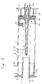
- FIG. 3 shows a slightly modified embodiment variant compared to FIG. 1.
- a ceramic gas distribution body 25 connects to the connector 10. This results in a flow-technically optimal transition from the filter into the outlet connection 16. Any deposits of particles that have not been separated are removed by the gas flow itself.
- the high-voltage bushing 26 is essentially composed of a single ceramic part, which is pressed against the honeycomb body 6 by a spring 27.
- the clamping device 14 is used only for fixing the electrode 8 in the high-voltage bushing 26.
- the side of the gas flow facing The high-voltage bushing 26 is designed as smooth as possible as half of the torus surface 28 in order to prevent the deposition of particles as much as possible.
- the high-voltage bushing 26 is sealed off from the honeycomb body 6 by a seal 29 that is resistant to high temperatures. As in the embodiment variant of FIG. 1, only a single electrical field is provided between the electrode 8 and the grounded housing 1.
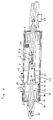
- the exhaust gas flows into the filter via a laterally arranged inlet connection 30.
- a high-voltage bushing 31 is arranged in the cover 2 adjacent to this inlet connection 30, the structure of which corresponds to the high-voltage bushing 9 of FIG. 1.
- a positive high voltage is applied to the terminal 32 assigned to this high-voltage bushing 31.
- the exhaust gases flowing into the filter via the inlet connection 30 first enter the chamber 33 surrounding the high-voltage bushing 31.
- This chamber 33 is delimited by the insulating disk 13, a ceramic tube 36 and an end plate 34, which are sealed with high-temperature-resistant seals 35.
- a ceramic tube 37 is inserted, which establishes the connection to the ionization channel 7 of the honeycomb body 6.
- an electrode 38 is applied, which is connected to the connecting terminal 32 via a connecting piece 39.
- the electrode 8 protruding into the ionization channel 7 from the opposite end is connected to ground. It is thereby achieved that the spray electrodes 8 'of the electrode 8 have a negative potential difference with respect to the electrode 38 interacting with them, which is essential for the ionization.
- the housing 1 is grounded and, together with the electrode 38, builds up the electric field for the separation of the particles.
- the electrode 8 is anchored in the cover 3 via a high-voltage bushing 40 and electrically connected to ground via a regulator 41. After flowing through the separation channels 6a, the cleaned exhaust gases enter the outflow chamber 42 and leave the filter via the outlet connection 43.
- FIG. 5 shows a filter in which a series of band-shaped electrodes 44 are provided in the honeycomb body 6.
- the cover 3 is insulated with a ceramic plate 49.
- the honeycomb body 6 is insulated from the outside with a ceramic tube 50 and an insulation layer 15.
- the basic structure of the ceramic honeycomb body 6 can be seen from FIG. 6.
- the illustration is valid for all the embodiment variants of FIGS. 1 to 5, but the various electrodes with the exception of the spray electrodes 8 'are not shown.
- the ceramic honeycomb body 6 has a multiplicity of channels 6a extending over its entire length, which are separated from one another by narrow webs 6b and ribs 6c arranged essentially concentrically to one another. These radially adjacent channels 6a are arranged offset in relation to one another in the circumferential direction, so that an image corresponding to a brick wall results, as can be seen in detail from the detailed illustration. In this way, the path of the electrical current is lengthened and the total electrical resistance of the ceramic body 6 is increased.
Landscapes
- Engineering & Computer Science (AREA)
- Chemical & Material Sciences (AREA)
- Chemical Kinetics & Catalysis (AREA)
- Combustion & Propulsion (AREA)
- General Engineering & Computer Science (AREA)
- Mechanical Engineering (AREA)
- Health & Medical Sciences (AREA)
- General Chemical & Material Sciences (AREA)
- Oil, Petroleum & Natural Gas (AREA)
- Analytical Chemistry (AREA)
- Environmental & Geological Engineering (AREA)
- Biomedical Technology (AREA)
- Toxicology (AREA)
- Processes For Solid Components From Exhaust (AREA)
- Electrostatic Separation (AREA)
Abstract
Claims (18)
- Dispositif de purification de particules provenant de gaz d'échappement, en particulier d'élimination de particules de suie provenant du gaz d'échappement de machines à combustion à compression d'air, comprenant :- au moins un canal (7) d'ionisation pour la production d'ions négatifs ;- des canaux (6a) de séparation disposés sensiblement parallèlement et de préférence coaxialement au canal d'ionisation (7), dans lesquels les particules sont déposées sur les parois des canaux (6a) de séparation et réduites en cendre ;- des moyens de génération d'au moins un champ électrique perpendiculaire à la direction du flux des gaz d'échappement ;caractérisé en ce que sont prévus des moyens (9b ; 28 ; 49) de retournement du flux des gaz d'échappement, qui dirigent les gaz provenant du canal (7) d'ionisation dans les canaux (6a) de séparation, en inversant la direction du flux.
- Dispositif selon la revendication 1, caractérisé en ce que sont prévues des électrodes (8) en vue de produire un champ électrique unique dont les lignes de champ englobent non seulement le canal (7) d'ionisation, mais encore les canaux (6a) de séparation.
- Dispositif selon la revendication 1, caractérisé en ce que sont prévues des électrodes (8, 44, 47, 48) pour la production de deux champs électriques dont l'un englobe le canal (7) d'ionisation, et l'autre englobe les canaux (6a) de séparation.
- Dispositif selon l'une des revendications 1 à 3, caractérisé en ce que la différence de potentiel entre les champs électriques se situe entre 3 et 30 kV, de préférence entre 5 et 20 kV.
- Dispositif selon l'une des revendications 1 à 4, caractérisé en ce que l'intensité des champs électriques se situe entre 100 et 1000 V/mm, de préférence entre 200 et 500 V/mm.
- Dispositif selon l'une des revendications 1 à 5, caractérisé en ce qu'est prévu un équipement d'apport d'un catalyseur dont le support est l'air, qui apporte ce catalyseur quand la température du flux de gaz d'échappement après un temps t est inférieur à A°C, t se situant entre 20 et 60 minutes et A étant inférieur à 500°C, de préférence inférieur à 300°C.
- Dispositif selon l'une des revendications 1 à 6, caractérisé en ce que non seulement le canal (7) d'ionisation mais également les canaux (6a) de séparation sont disposés comme des canaux ouverts des deux côtés disposés dans un corps unique en céramique.
- Dispositif selon la revendication 7, caractérisé en ce que le corps (6) en céramique se compose essentiellement d'un matériau imperméable au gaz.
- Dispositif selon l'une des revendications 7 ou 8, caractérisé en ce que le corps (6) en céramique est construit de manière sensiblement cylindrique, le canal (7) d'ionisation étant disposé dans la zone de l'axe du cylindre et les canaux (6a) de séparation étant disposés autour du canal (7) d'ionisation.
- Dispositif selon l'une des revendications 1 à 9, caractérisé en ce que les canaux (6a) de séparation présentent une section transversale sensiblement rectangulaire, le côté le plus long étant orienté perpendiculairement à la direction du champ électrique et le rapport entre la longueur et la largeur se situant entre 4:1 et 10:1.
- Dispositif selon l'une des revendications 1 à 10, caractérisé en ce que les canaux (6a) de séparation sont disposés décalés les uns par rapport aux autres.
- Dispositif selon l'une des revendications 1 à 11, caractérisé en ce que les parois des canaux (6a) de séparation sont recouvertes d'un catalyseur qui favorise l'oxydation des hydrocarbures.
- Dispositif selon la revendication 12, caractérisé en ce que des portions des parois des canaux (6a) de séparation sont recouvertes au moyen d'un catalyseur favorisant l'oxydation des hydrocarbures, et que d'autres portions des parois des canaux (6a) de séparation sont recouvertes avec un autre catalyseur de réduction.
- Dispositif selon l'une des revendications 1 à 13, caractérisé en ce que sont prévues deux électrodes (8) disposées de la façon suivante :- à l'intérieur du canal (7) d'ionisation se trouve une électrode (8) équipée de préférence d'électrodes (8') d'émission en forme de disque denté ;- sur la surface extérieure du corps (6) en céramique est prévue une électrode reliée à la masse, qui est construite de préférence à partir du logement (1). (Fig. 1, Fig. 3)
- Dispositif selon l'une des revendications 1 à 13, caractérisé en ce que les électrodes (8, 44, 47, 48) sont disposées de la manière suivante :- à l'intérieur du canal (7) d'ionisation se trouve une électrode (8) équipée de préférence d'électrodes (8') d'émission sous forme de disque denté ;- sur la paroi du canal (7) d'ionisation se trouve une électrode (47) reliée à la masse ;- entre les canaux (6a) de séparation est disposée au moins une électrode (44) de champ ;- sur la surface extérieure du corps (6) en céramique est prévu de préférence une électrode (48) reliée à la masse. (Fig. 5)
- Dispositif selon la revendication 15, caractérisé en ce que l'électrode d'émission (8) et l'électrode de champ (44) se trouvent à un potentiel identique.
- Dispositif selon l'une des revendications 1 à 13, caractérisé en ce que les électrodes (8, 18) sont disposées de la façon suivante :- à l'intérieur du canal (7) d'ionisation se trouve une électrode (8) d'émission de préférence sous la forme de disque denté, sensiblement reliée à la masse ;- sur la paroi du canal (7) d'ionisation se trouve une électrode susceptible d'être reliée à un potentiel à haute tension.
- Corps céramique pour la réalisation d'un dispositif selon l'une des revendications 1 à 17, caractérisé en ce qu'est prévu un canal (7) central d'ionisation, et en ce que sont disposés parallèlement à ce canal (7) d'ionisation une pluralité de canaux (6) de séparation.
Applications Claiming Priority (2)
| Application Number | Priority Date | Filing Date | Title |
|---|---|---|---|
| AT937/90 | 1990-04-23 | ||
| AT93790 | 1990-04-23 |
Publications (2)
| Publication Number | Publication Date |
|---|---|
| EP0526552A1 EP0526552A1 (fr) | 1993-02-10 |
| EP0526552B1 true EP0526552B1 (fr) | 1993-12-29 |
Family
ID=3503273
Family Applications (1)
| Application Number | Title | Priority Date | Filing Date |
|---|---|---|---|
| EP91908758A Expired - Lifetime EP0526552B1 (fr) | 1990-04-23 | 1991-04-23 | Procede et dispositif pour l'epuration de particules contenues dans des gaz d'echappement |
Country Status (5)
| Country | Link |
|---|---|
| EP (1) | EP0526552B1 (fr) |
| AU (1) | AU7755491A (fr) |
| DE (1) | DE59100781D1 (fr) |
| ES (1) | ES2048014T3 (fr) |
| WO (1) | WO1991016528A1 (fr) |
Cited By (1)
| Publication number | Priority date | Publication date | Assignee | Title |
|---|---|---|---|---|
| US7514047B2 (en) | 2003-01-15 | 2009-04-07 | Toyota Jidosha Kabushiki Kaisha | Exhaust gas purifying apparatus |
Families Citing this family (9)
| Publication number | Priority date | Publication date | Assignee | Title |
|---|---|---|---|---|
| GB9218207D0 (en) * | 1992-08-27 | 1992-10-14 | Atomic Energy Authority Uk | The purification of internal combustion engine exhaust emissions |
| DE4236242A1 (de) * | 1992-10-27 | 1994-04-28 | Dornier Gmbh | Verfahren zur Minderung von Russpartikeln in Abgasströmen |
| ATA256293A (de) * | 1993-12-17 | 1998-10-15 | Fleck Carl M Dr | Elektrofilter zum abscheiden von russpartikeln aus den abgasen von brennkraftmaschinen |
| DE19739181A1 (de) * | 1997-09-08 | 1999-03-11 | Abb Research Ltd | Entladungsreaktor und Verwendung desselben |
| AT409653B (de) | 1999-11-10 | 2002-10-25 | Fleck Carl M Dr | Verfahren und vorrichtung zum abscheiden von russpartikel aus einem abgasstrom, insbesondere einer diesel-brennkraftmaschine |
| FR2861802B1 (fr) * | 2003-10-30 | 2006-01-20 | Renault Sas | Dispositif electronique pour controler le fonctionnement d'un filtre electrostatique dispose dans la ligne d'echappement d'un vehicule automobile |
| WO2006128711A1 (fr) * | 2005-06-03 | 2006-12-07 | Emitec Gesellschaft Für Emissionstechnologie Mbh | Procede et dispositif pour limiter la teneur en particules de gaz d'echappement |
| IL182389A (en) * | 2007-04-10 | 2010-11-30 | Yefim Riskin | Method of air purification from dust and electrostatic filter |
| EP2641659A1 (fr) * | 2012-03-20 | 2013-09-25 | Siemens Aktiengesellschaft | Précipitateur électrostatique humide amélioré pour nettoyer les gaz combustibles |
Family Cites Families (6)
| Publication number | Priority date | Publication date | Assignee | Title |
|---|---|---|---|---|
| FR1050120A (fr) * | 1952-02-01 | 1954-01-05 | Onera (Off Nat Aerospatiale) | Capteur de poussières |
| US4505723A (en) * | 1981-10-20 | 1985-03-19 | Efb Inc. | Filter apparatus |
| DE3324478A1 (de) * | 1983-07-07 | 1985-01-24 | Robert Bosch Gmbh, 7000 Stuttgart | Vorrichtung zum reinigen von gasen |
| SE459320B (sv) * | 1986-12-16 | 1989-06-26 | Thore Haraldson | Avgasrenare foer avgaser fraan foerbraenningsmotorer och foerbraenningsanlaeggningar foer fasta och flytande braenslen |
| DE3705979A1 (de) * | 1987-02-25 | 1988-09-08 | Navsat Gmbh | Abgasrussfilter |
| US4979364A (en) * | 1988-03-11 | 1990-12-25 | Fleck Carl M | Diesel fuel exhaust gas filter |
-
1991
- 1991-04-23 DE DE91908758T patent/DE59100781D1/de not_active Expired - Fee Related
- 1991-04-23 ES ES91908758T patent/ES2048014T3/es not_active Expired - Lifetime
- 1991-04-23 AU AU77554/91A patent/AU7755491A/en not_active Abandoned
- 1991-04-23 WO PCT/AT1991/000059 patent/WO1991016528A1/fr not_active Ceased
- 1991-04-23 EP EP91908758A patent/EP0526552B1/fr not_active Expired - Lifetime
Cited By (1)
| Publication number | Priority date | Publication date | Assignee | Title |
|---|---|---|---|---|
| US7514047B2 (en) | 2003-01-15 | 2009-04-07 | Toyota Jidosha Kabushiki Kaisha | Exhaust gas purifying apparatus |
Also Published As
| Publication number | Publication date |
|---|---|
| AU7755491A (en) | 1991-11-11 |
| DE59100781D1 (de) | 1994-02-10 |
| ES2048014T3 (es) | 1994-03-01 |
| WO1991016528A1 (fr) | 1991-10-31 |
| EP0526552A1 (fr) | 1993-02-10 |
Similar Documents
| Publication | Publication Date | Title |
|---|---|---|
| EP0537219B1 (fr) | Procede et dispositif d'epuration des gaz d'echappement | |
| EP0152623B1 (fr) | Appareillage d'élimination de particules solides des gaz d'échappement des engins à combustion | |
| EP1179673B1 (fr) | Dispositif de recirculation de gaz dans un moteur à combustion | |
| EP0650551A1 (fr) | Procede et dispositif d'elimination de particules dans des gaz d'echappement de moteurs a combustion interne. | |
| DE102005013183A1 (de) | Mehrstufiger raumeffizienter elektrostatischer Kollektor | |
| EP0526552B1 (fr) | Procede et dispositif pour l'epuration de particules contenues dans des gaz d'echappement | |
| EP2616646B1 (fr) | Dispositif pour traiter des gaz d'échappement contenant des particules de suie | |
| DE102007020504A1 (de) | Elektrostatischer Abscheider mit Beseitigung von Verunreinigungen der Masseelektrode | |
| DE3804779C2 (fr) | ||
| EP0256325B1 (fr) | Filtre d'élimination des particules de suie, en particulier dans le courant des gas d'échappement d'un moteur diesel | |
| EP2603678B1 (fr) | Procédé et dispositif pour réduire les particules de suie dans les gaz d'échappement d'un moteur à combustion interne | |
| WO2014114408A1 (fr) | Dispositif et procédé destinés à traiter un gaz d'échappement comportant des particules | |
| DE3323926C2 (de) | Vorrichtung zum Reinigen von Gasen | |
| EP0715894B1 (fr) | Installation de filtrage électrostatique | |
| EP0307656A2 (fr) | Coagulateur pour un dispositif de purification des gaz d'échappement des moteurs à combustion interne | |
| EP2153902B1 (fr) | Séparateur électrostatique et système de chauffage | |
| EP2820258B1 (fr) | Dispositif pour traiter un flux gazeux s'écoulant radialement vers l'extérieur d'une zone centrale | |
| EP0885647B1 (fr) | Dispositif pour la dissociation d'oxydes d'azote dans le gaz d'échappement de moteurs à combustion | |
| AT395827B (de) | Verfahren zum verbrennen von in abgasen enthaltenen aerosolen, insbesondere russ | |
| DE3627734C2 (fr) | ||
| DE3936421A1 (de) | Einrichtung zur entfernung von russpartikel aus abgasen | |
| DE3902812C1 (en) | Electrostatic precipitator for the removal of particulates from the exhaust of internal-combustion devices or internal combustion engines and the catalytically initiated combustion of said particulates by means of an electric heating device | |
| DE202012100052U1 (de) | Anordnung einer beheizbaren Elektrode in einem Kamin oder einem Abgaskanal | |
| DE102024102234A1 (de) | Elektrostatischer Kondensationsabscheider, elektrostatisch verstärktes Kondensationssystem sowie Verfahren zur elektrostatischen Kondensationsabscheidung | |
| DE102006026372B4 (de) | Abgasreinigungsvorrichtung für Brennstoffaggregate |
Legal Events
| Date | Code | Title | Description |
|---|---|---|---|
| PUAI | Public reference made under article 153(3) epc to a published international application that has entered the european phase |
Free format text: ORIGINAL CODE: 0009012 |
|
| 17P | Request for examination filed |
Effective date: 19921022 |
|
| AK | Designated contracting states |
Kind code of ref document: A1 Designated state(s): DE ES FR GB IT SE |
|
| 17Q | First examination report despatched |
Effective date: 19920301 |
|
| GRAA | (expected) grant |
Free format text: ORIGINAL CODE: 0009210 |
|
| AK | Designated contracting states |
Kind code of ref document: B1 Designated state(s): DE ES FR GB IT SE |
|
| GBT | Gb: translation of ep patent filed (gb section 77(6)(a)/1977) |
Effective date: 19940111 |
|
| REF | Corresponds to: |
Ref document number: 59100781 Country of ref document: DE Date of ref document: 19940210 |
|
| ITF | It: translation for a ep patent filed | ||
| REG | Reference to a national code |
Ref country code: ES Ref legal event code: FG2A Ref document number: 2048014 Country of ref document: ES Kind code of ref document: T3 |
|
| ET | Fr: translation filed | ||
| PLBE | No opposition filed within time limit |
Free format text: ORIGINAL CODE: 0009261 |
|
| STAA | Information on the status of an ep patent application or granted ep patent |
Free format text: STATUS: NO OPPOSITION FILED WITHIN TIME LIMIT |
|
| 26N | No opposition filed | ||
| EAL | Se: european patent in force in sweden |
Ref document number: 91908758.5 |
|
| PGFP | Annual fee paid to national office [announced via postgrant information from national office to epo] |
Ref country code: SE Payment date: 19970318 Year of fee payment: 7 |
|
| PGFP | Annual fee paid to national office [announced via postgrant information from national office to epo] |
Ref country code: ES Payment date: 19970415 Year of fee payment: 7 |
|
| PGFP | Annual fee paid to national office [announced via postgrant information from national office to epo] |
Ref country code: GB Payment date: 19970423 Year of fee payment: 7 |
|
| PGFP | Annual fee paid to national office [announced via postgrant information from national office to epo] |
Ref country code: FR Payment date: 19970428 Year of fee payment: 7 |
|
| PGFP | Annual fee paid to national office [announced via postgrant information from national office to epo] |
Ref country code: DE Payment date: 19970528 Year of fee payment: 7 |
|
| PG25 | Lapsed in a contracting state [announced via postgrant information from national office to epo] |
Ref country code: GB Free format text: LAPSE BECAUSE OF NON-PAYMENT OF DUE FEES Effective date: 19980423 |
|
| PG25 | Lapsed in a contracting state [announced via postgrant information from national office to epo] |
Ref country code: SE Free format text: LAPSE BECAUSE OF NON-PAYMENT OF DUE FEES Effective date: 19980424 Ref country code: ES Free format text: LAPSE BECAUSE OF EXPIRATION OF PROTECTION Effective date: 19980424 |
|
| PG25 | Lapsed in a contracting state [announced via postgrant information from national office to epo] |
Ref country code: FR Free format text: THE PATENT HAS BEEN ANNULLED BY A DECISION OF A NATIONAL AUTHORITY Effective date: 19980430 |
|
| GBPC | Gb: european patent ceased through non-payment of renewal fee |
Effective date: 19980423 |
|
| EUG | Se: european patent has lapsed |
Ref document number: 91908758.5 |
|
| PG25 | Lapsed in a contracting state [announced via postgrant information from national office to epo] |
Ref country code: DE Free format text: LAPSE BECAUSE OF NON-PAYMENT OF DUE FEES Effective date: 19990202 |
|
| REG | Reference to a national code |
Ref country code: FR Ref legal event code: ST |
|
| REG | Reference to a national code |
Ref country code: ES Ref legal event code: FD2A Effective date: 20000301 |
|
| PG25 | Lapsed in a contracting state [announced via postgrant information from national office to epo] |
Ref country code: IT Free format text: LAPSE BECAUSE OF NON-PAYMENT OF DUE FEES;WARNING: LAPSES OF ITALIAN PATENTS WITH EFFECTIVE DATE BEFORE 2007 MAY HAVE OCCURRED AT ANY TIME BEFORE 2007. THE CORRECT EFFECTIVE DATE MAY BE DIFFERENT FROM THE ONE RECORDED. Effective date: 20050423 |