EP0526552B1 - Process and device for removing particles from exhaust gases - Google Patents
Process and device for removing particles from exhaust gases Download PDFInfo
- Publication number
- EP0526552B1 EP0526552B1 EP91908758A EP91908758A EP0526552B1 EP 0526552 B1 EP0526552 B1 EP 0526552B1 EP 91908758 A EP91908758 A EP 91908758A EP 91908758 A EP91908758 A EP 91908758A EP 0526552 B1 EP0526552 B1 EP 0526552B1
- Authority
- EP
- European Patent Office
- Prior art keywords
- ionising
- duct
- electrode
- ducts
- separator
- Prior art date
- Legal status (The legal status is an assumption and is not a legal conclusion. Google has not performed a legal analysis and makes no representation as to the accuracy of the status listed.)
- Expired - Lifetime
Links
Images


Classifications
-
- B—PERFORMING OPERATIONS; TRANSPORTING
- B01—PHYSICAL OR CHEMICAL PROCESSES OR APPARATUS IN GENERAL
- B01D—SEPARATION
- B01D53/00—Separation of gases or vapours; Recovering vapours of volatile solvents from gases; Chemical or biological purification of waste gases, e.g. engine exhaust gases, smoke, fumes, flue gases, aerosols
- B01D53/32—Separation of gases or vapours; Recovering vapours of volatile solvents from gases; Chemical or biological purification of waste gases, e.g. engine exhaust gases, smoke, fumes, flue gases, aerosols by electrical effects other than those provided for in group B01D61/00
- B01D53/323—Separation of gases or vapours; Recovering vapours of volatile solvents from gases; Chemical or biological purification of waste gases, e.g. engine exhaust gases, smoke, fumes, flue gases, aerosols by electrical effects other than those provided for in group B01D61/00 by electrostatic effects or by high-voltage electric fields
-
- B—PERFORMING OPERATIONS; TRANSPORTING
- B01—PHYSICAL OR CHEMICAL PROCESSES OR APPARATUS IN GENERAL
- B01D—SEPARATION
- B01D53/00—Separation of gases or vapours; Recovering vapours of volatile solvents from gases; Chemical or biological purification of waste gases, e.g. engine exhaust gases, smoke, fumes, flue gases, aerosols
- B01D53/34—Chemical or biological purification of waste gases
- B01D53/92—Chemical or biological purification of waste gases of engine exhaust gases
- B01D53/94—Chemical or biological purification of waste gases of engine exhaust gases by catalytic processes
-
- B—PERFORMING OPERATIONS; TRANSPORTING
- B03—SEPARATION OF SOLID MATERIALS USING LIQUIDS OR USING PNEUMATIC TABLES OR JIGS; MAGNETIC OR ELECTROSTATIC SEPARATION OF SOLID MATERIALS FROM SOLID MATERIALS OR FLUIDS; SEPARATION BY HIGH-VOLTAGE ELECTRIC FIELDS
- B03C—MAGNETIC OR ELECTROSTATIC SEPARATION OF SOLID MATERIALS FROM SOLID MATERIALS OR FLUIDS; SEPARATION BY HIGH-VOLTAGE ELECTRIC FIELDS
- B03C3/00—Separating dispersed particles from gases or vapour, e.g. air, by electrostatic effect
- B03C3/017—Combinations of electrostatic separation with other processes, not otherwise provided for
-
- B—PERFORMING OPERATIONS; TRANSPORTING
- B03—SEPARATION OF SOLID MATERIALS USING LIQUIDS OR USING PNEUMATIC TABLES OR JIGS; MAGNETIC OR ELECTROSTATIC SEPARATION OF SOLID MATERIALS FROM SOLID MATERIALS OR FLUIDS; SEPARATION BY HIGH-VOLTAGE ELECTRIC FIELDS
- B03C—MAGNETIC OR ELECTROSTATIC SEPARATION OF SOLID MATERIALS FROM SOLID MATERIALS OR FLUIDS; SEPARATION BY HIGH-VOLTAGE ELECTRIC FIELDS
- B03C3/00—Separating dispersed particles from gases or vapour, e.g. air, by electrostatic effect
- B03C3/02—Plant or installations having external electricity supply
- B03C3/04—Plant or installations having external electricity supply dry type
- B03C3/12—Plant or installations having external electricity supply dry type characterised by separation of ionising and collecting stations
-
- B—PERFORMING OPERATIONS; TRANSPORTING
- B03—SEPARATION OF SOLID MATERIALS USING LIQUIDS OR USING PNEUMATIC TABLES OR JIGS; MAGNETIC OR ELECTROSTATIC SEPARATION OF SOLID MATERIALS FROM SOLID MATERIALS OR FLUIDS; SEPARATION BY HIGH-VOLTAGE ELECTRIC FIELDS
- B03C—MAGNETIC OR ELECTROSTATIC SEPARATION OF SOLID MATERIALS FROM SOLID MATERIALS OR FLUIDS; SEPARATION BY HIGH-VOLTAGE ELECTRIC FIELDS
- B03C3/00—Separating dispersed particles from gases or vapour, e.g. air, by electrostatic effect
- B03C3/34—Constructional details or accessories or operation thereof
- B03C3/36—Controlling flow of gases or vapour
-
- B—PERFORMING OPERATIONS; TRANSPORTING
- B03—SEPARATION OF SOLID MATERIALS USING LIQUIDS OR USING PNEUMATIC TABLES OR JIGS; MAGNETIC OR ELECTROSTATIC SEPARATION OF SOLID MATERIALS FROM SOLID MATERIALS OR FLUIDS; SEPARATION BY HIGH-VOLTAGE ELECTRIC FIELDS
- B03C—MAGNETIC OR ELECTROSTATIC SEPARATION OF SOLID MATERIALS FROM SOLID MATERIALS OR FLUIDS; SEPARATION BY HIGH-VOLTAGE ELECTRIC FIELDS
- B03C3/00—Separating dispersed particles from gases or vapour, e.g. air, by electrostatic effect
- B03C3/34—Constructional details or accessories or operation thereof
- B03C3/40—Electrode constructions
- B03C3/41—Ionising-electrodes
-
- F—MECHANICAL ENGINEERING; LIGHTING; HEATING; WEAPONS; BLASTING
- F01—MACHINES OR ENGINES IN GENERAL; ENGINE PLANTS IN GENERAL; STEAM ENGINES
- F01N—GAS-FLOW SILENCERS OR EXHAUST APPARATUS FOR MACHINES OR ENGINES IN GENERAL; GAS-FLOW SILENCERS OR EXHAUST APPARATUS FOR INTERNAL-COMBUSTION ENGINES
- F01N3/00—Exhaust or silencing apparatus having means for purifying, rendering innocuous, or otherwise treating exhaust
- F01N3/01—Exhaust or silencing apparatus having means for purifying, rendering innocuous, or otherwise treating exhaust by means of electric or electrostatic separators
-
- F—MECHANICAL ENGINEERING; LIGHTING; HEATING; WEAPONS; BLASTING
- F01—MACHINES OR ENGINES IN GENERAL; ENGINE PLANTS IN GENERAL; STEAM ENGINES
- F01N—GAS-FLOW SILENCERS OR EXHAUST APPARATUS FOR MACHINES OR ENGINES IN GENERAL; GAS-FLOW SILENCERS OR EXHAUST APPARATUS FOR INTERNAL-COMBUSTION ENGINES
- F01N3/00—Exhaust or silencing apparatus having means for purifying, rendering innocuous, or otherwise treating exhaust
- F01N3/02—Exhaust or silencing apparatus having means for purifying, rendering innocuous, or otherwise treating exhaust for cooling, or for removing solid constituents of, exhaust
- F01N3/021—Exhaust or silencing apparatus having means for purifying, rendering innocuous, or otherwise treating exhaust for cooling, or for removing solid constituents of, exhaust by means of filters
- F01N3/0211—Arrangements for mounting filtering elements in housing, e.g. with means for compensating thermal expansion or vibration
-
- F—MECHANICAL ENGINEERING; LIGHTING; HEATING; WEAPONS; BLASTING
- F01—MACHINES OR ENGINES IN GENERAL; ENGINE PLANTS IN GENERAL; STEAM ENGINES
- F01N—GAS-FLOW SILENCERS OR EXHAUST APPARATUS FOR MACHINES OR ENGINES IN GENERAL; GAS-FLOW SILENCERS OR EXHAUST APPARATUS FOR INTERNAL-COMBUSTION ENGINES
- F01N3/00—Exhaust or silencing apparatus having means for purifying, rendering innocuous, or otherwise treating exhaust
- F01N3/02—Exhaust or silencing apparatus having means for purifying, rendering innocuous, or otherwise treating exhaust for cooling, or for removing solid constituents of, exhaust
- F01N3/021—Exhaust or silencing apparatus having means for purifying, rendering innocuous, or otherwise treating exhaust for cooling, or for removing solid constituents of, exhaust by means of filters
- F01N3/022—Exhaust or silencing apparatus having means for purifying, rendering innocuous, or otherwise treating exhaust for cooling, or for removing solid constituents of, exhaust by means of filters characterised by specially adapted filtering structure, e.g. honeycomb, mesh or fibrous
- F01N3/0222—Exhaust or silencing apparatus having means for purifying, rendering innocuous, or otherwise treating exhaust for cooling, or for removing solid constituents of, exhaust by means of filters characterised by specially adapted filtering structure, e.g. honeycomb, mesh or fibrous the structure being monolithic, e.g. honeycombs
-
- F—MECHANICAL ENGINEERING; LIGHTING; HEATING; WEAPONS; BLASTING
- F01—MACHINES OR ENGINES IN GENERAL; ENGINE PLANTS IN GENERAL; STEAM ENGINES
- F01N—GAS-FLOW SILENCERS OR EXHAUST APPARATUS FOR MACHINES OR ENGINES IN GENERAL; GAS-FLOW SILENCERS OR EXHAUST APPARATUS FOR INTERNAL-COMBUSTION ENGINES
- F01N3/00—Exhaust or silencing apparatus having means for purifying, rendering innocuous, or otherwise treating exhaust
- F01N3/08—Exhaust or silencing apparatus having means for purifying, rendering innocuous, or otherwise treating exhaust for rendering innocuous
- F01N3/10—Exhaust or silencing apparatus having means for purifying, rendering innocuous, or otherwise treating exhaust for rendering innocuous by thermal or catalytic conversion of noxious components of exhaust
- F01N3/24—Exhaust or silencing apparatus having means for purifying, rendering innocuous, or otherwise treating exhaust for rendering innocuous by thermal or catalytic conversion of noxious components of exhaust characterised by constructional aspects of converting apparatus
- F01N3/28—Construction of catalytic reactors
- F01N3/2882—Catalytic reactors combined or associated with other devices, e.g. exhaust silencers or other exhaust purification devices
-
- B—PERFORMING OPERATIONS; TRANSPORTING
- B01—PHYSICAL OR CHEMICAL PROCESSES OR APPARATUS IN GENERAL
- B01D—SEPARATION
- B01D2259/00—Type of treatment
- B01D2259/80—Employing electric, magnetic, electromagnetic or wave energy, or particle radiation
- B01D2259/818—Employing electrical discharges or the generation of a plasma
-
- B—PERFORMING OPERATIONS; TRANSPORTING
- B03—SEPARATION OF SOLID MATERIALS USING LIQUIDS OR USING PNEUMATIC TABLES OR JIGS; MAGNETIC OR ELECTROSTATIC SEPARATION OF SOLID MATERIALS FROM SOLID MATERIALS OR FLUIDS; SEPARATION BY HIGH-VOLTAGE ELECTRIC FIELDS
- B03C—MAGNETIC OR ELECTROSTATIC SEPARATION OF SOLID MATERIALS FROM SOLID MATERIALS OR FLUIDS; SEPARATION BY HIGH-VOLTAGE ELECTRIC FIELDS
- B03C2201/00—Details of magnetic or electrostatic separation
- B03C2201/10—Ionising electrode with two or more serrated ends or sides
-
- F—MECHANICAL ENGINEERING; LIGHTING; HEATING; WEAPONS; BLASTING
- F01—MACHINES OR ENGINES IN GENERAL; ENGINE PLANTS IN GENERAL; STEAM ENGINES
- F01N—GAS-FLOW SILENCERS OR EXHAUST APPARATUS FOR MACHINES OR ENGINES IN GENERAL; GAS-FLOW SILENCERS OR EXHAUST APPARATUS FOR INTERNAL-COMBUSTION ENGINES
- F01N2250/00—Combinations of different methods of purification
- F01N2250/02—Combinations of different methods of purification filtering and catalytic conversion
-
- F—MECHANICAL ENGINEERING; LIGHTING; HEATING; WEAPONS; BLASTING
- F01—MACHINES OR ENGINES IN GENERAL; ENGINE PLANTS IN GENERAL; STEAM ENGINES
- F01N—GAS-FLOW SILENCERS OR EXHAUST APPARATUS FOR MACHINES OR ENGINES IN GENERAL; GAS-FLOW SILENCERS OR EXHAUST APPARATUS FOR INTERNAL-COMBUSTION ENGINES
- F01N2330/00—Structure of catalyst support or particle filter
- F01N2330/06—Ceramic, e.g. monoliths
-
- Y—GENERAL TAGGING OF NEW TECHNOLOGICAL DEVELOPMENTS; GENERAL TAGGING OF CROSS-SECTIONAL TECHNOLOGIES SPANNING OVER SEVERAL SECTIONS OF THE IPC; TECHNICAL SUBJECTS COVERED BY FORMER USPC CROSS-REFERENCE ART COLLECTIONS [XRACs] AND DIGESTS
- Y02—TECHNOLOGIES OR APPLICATIONS FOR MITIGATION OR ADAPTATION AGAINST CLIMATE CHANGE
- Y02T—CLIMATE CHANGE MITIGATION TECHNOLOGIES RELATED TO TRANSPORTATION
- Y02T10/00—Road transport of goods or passengers
- Y02T10/10—Internal combustion engine [ICE] based vehicles
- Y02T10/12—Improving ICE efficiencies
Definitions
- the exhaust gases to be filtered can pass through the porous wall common to two such filter cells, while the aerosols cannot pass through the pores and are deposited in the cell which is open on the inlet side.
- These filters are partly made of high-temperature-resistant ceramic material and are preferably coated or doped with catalytic substances, so that when the excess of oxygen is present, the soot particles separated are burnt even below 600 ° C. Since these temperatures can only be reached at full throttle, there is a considerable build-up of back pressure in the periods in between, which reduces the engine output in an unpleasant manner.
- DE-A 33 24 886 it is known from DE-A 33 24 886 to first agglomerate particles into larger particles using an electric field and then to suck them into a waveguide.
- DE-A 38 04 779 has disclosed a device for removing soot particles from the exhaust gas stream of a diesel internal combustion engine, in which a soot particle collection section is arranged in an exhaust gas line.
- This essentially consists of an ionization path in which an ultraviolet light source is arranged.
- This is followed by a central electrode, which is surrounded by two concentric electrodes, the inner of which is provided with openings.
- the central electrode is connected to a common potential of a low and a high voltage source, the first of which is connected to the second pole of the low voltage source and the second to the second pole of the high voltage source.
- the soot particles contained in the exhaust gas stream are charged in the area of the ionization path and are deflected in the area of the cylindrical electrodes due to the field prevailing there towards the central electrode, penetrate the inner cylindrical electrode and accumulate on the innermost electrode. If the deposits reach a height at which they touch the inner cylindrical electrode, they form a short circuit for the low-voltage source and burn off.
- the disadvantage of this known device is that due to the very low potential of the inner cylindrical electrode compared to the outer electrode, the soot particles also come into contact with the outside of this electrode, but these soot particles could scarcely burn and with a corresponding thickness Layer due to mechanical influences such as vibrations and the like. dissolve in larger flakes.
- a mechanical separator e.g. to arrange a cyclone separator, which results in a correspondingly high construction effort and a very considerable space requirement.
- GB-A 411.807 shows a device in which exhaust gas components are first separated by electric fields in order to avoid poisoning the subsequent catalytic converter. The disposal of the separated exhaust gas components has not been clarified.
- CH-A-372 033 essentially relates to an electrostatic filter.
- the exhaust gas is previously cooled in a heat exchanger.
- DE-B-1 080 349 describes an electrostatic filter which is coupled to a silencer.
- the muffler consists in a known manner of a series of baffles.
- From US-A-2 142 128 an electrical separation device is known with which particles suspended in a gas stream can be separated out. The particles separated by gravity are collected in the sump of the device and withdrawn from there. Such devices have proven ineffective in effect.
- the object of the invention is to avoid these disadvantages and to provide a method which, in a simple manner, makes it possible not only to separate soot particles, but also to completely destroy them, a long service life being required with largely no maintenance.
- means for deflecting the exhaust gas flow are provided, which direct the gases flowing out of the ionization channel into the separation channels by reversing the direction of flow.
- the deflection of the gas flow enables a particularly space-saving arrangement of the components in the filter which favors electrical insulation. This results, among other things, from the fact that the deflection enables the inflow and outflow openings to be arranged relatively far from the high-voltage bushing.
- a particularly simple and inexpensive construction of the filter is possible. All that is required is a pair of electrodes, including leads and connections. However, the voltage which the electric field generates must be chosen higher because of the double task.
- these electric fields can be set independently of one another and optimally for their respective task.
- each field can have a relatively small potential difference.
- the potential difference of the electric fields is between 3 and 30 kV, preferably between 5 and 20 kV. This ensures an optimal degree of separation under manageable conditions.
- the field strength of the electrical fields is between 100 and 1000 V / mm, preferably between 200 and 500 V / mm.
- the long-term effectiveness of the filter according to the invention can be considerably improved by temporarily introducing a catalyst in an airborne form into the exhaust gas stream. In the simplest case, this can be carried out operationally by means of a storage container which is carried and from which a certain amount of the catalyst is released every 50 operating hours of the engine. However, it is particularly advantageous if the catalyst is introduced if the temperature of the exhaust gas stream is less than A ° C. over a time t, t being between 20 and 60 minutes and A being less than 500 ° C., preferably less than 300 ° C is. Long-term operation at low temperatures may make it necessary to renew the catalyst layer. The temperature-dependent control enables optimum degrees of separation to be achieved with low additions of the catalyst.
- both the ionization channel and the separation channels are arranged as channels open on both sides in a single ceramic body.
- the ceramic body consists of an essentially gastight material. As a result, the flow paths of the exhaust gas are well-defined and predictable.
- the ceramic body is preferably of essentially cylindrical construction, the ionization channel being arranged in the region of the cylinder axis and the deposition channels being arranged around the ionization channel.
- a filter can be made in the dimensions of a conventional muffler.
- the deposition channels have an essentially rectangular cross section, the longer side being oriented transversely to the direction of the electrical field and the ratio between length and width being between 4: 1 and 10: 1.
- a further reduction in the electrical currents flowing through the ceramic body can be achieved by extending the paths which these have to cover in the ceramic honeycomb body.
- the separation channels are therefore preferably offset from one another.
- the efficiency of the device can be improved by coating the walls of the separation channels with a catalyst which promotes the oxidation of hydrocarbons.
- Metal oxide catalysts can be used in a known manner as catalysts, e.g. those based on FeO.
- An additional function of the device according to the invention is achieved in that parts of the walls of the separation channels are coated with a catalyst which promotes the oxidation of hydrocarbons and in that other parts of the walls of the separation channels are coated with a further reducing catalyst. This is carried out, for example, in such a way that the wall surfaces lying on the inside of the ceramic body are coated with one catalyst and the other catalyst is applied to the outside thereof.
- the reducing catalyst can break down nitrogen oxides into nitrogen and oxygen.
- This embodiment variant corresponds to a method with two independent electrical fields.
- the spray electrode and the field electrode are at a common potential. As a result, only a high-voltage bushing is required.
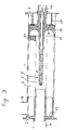
- the exhaust gas filter consists of an essentially cylindrical housing 1, which is closed at the ends by covers 2 and 3. Inside, a ceramic honeycomb body 6 is arranged, which is circular in cross-section. This ceramic honeycomb body 6 can also be composed of several circular ring segments.
- the ionization channel 7 is arranged centrally in the honeycomb body 6.
- the gas to be cleaned flows into the filter through a pipe socket 10 arranged in the cover 2.
- a ceramic tube 11 is provided, which is sealed at one end with a seal 12 with respect to the cover 2.
- the tube 11 is connected to the ionization channel 7 of the honeycomb body 6.
- the electrode 8 is held by a high-voltage bushing 9, which is used to isolate the high-voltage parts from the grounded housing 1 together with the cover 3.
- the high-voltage bushing 9 consists of three ceramic parts 9a, 9b and 9c.
- the part 9a encloses the shaft 8a of the electrode 8 and is provided with ribs on its circumference in order to extend the leakage paths of the current.
- Partly surrounding part 9a is cup-shaped part 9b, which is also provided with ribs. In this part, the gases are redirected so that they continue to flow through the separation channels 6a.
- the parts 9a and 9b are supported on the cover 3 via shoulders, an insulating disk 13 being able to be interposed.
- the part 9c of the high-voltage bushing 9 arranged on the outside is supported on the outside of the cover 3.
- a tensioning device 14 exerts a tensile stress on the shaft of the electrode 8, so that the parts 9a and 9c of the high-voltage bushing 9 are braced against one another.
- the high-voltage bushing 9 is made in a manner known per se in the way and from the material, as is customary for high-voltage insulators.
- the ceramic body 6 is provided with an insulation layer 15, which is also used to support the housing 1.
- a ceramic tube 23 in the area of the high-voltage bushing 9 additionally serves for insulation.
- the cleaned ones Exhaust gases leave the filter via an outlet connection 16 arranged on the circumference of the housing 1.
- FIG. 2 essentially corresponds to the variant described above. The difference, however, is that two separate electric fields are provided for ionization and deposition.
- the ionization field is established between the central electrode 8 and an earthed electrode 17 arranged on the wall of the ionization channel 7. This makes it possible to select the voltage to be applied to the electrode 8 to be lower than in the first embodiment variant.
- the field for separating the particles is generated between the grounded electrode 17 and a further electrode 18 arranged on the outer circumference of the ceramic honeycomb body 6. This electrode 18 can be at a negative or positive potential.
- the insulation from the housing 1 takes place via a ceramic sleeve 18 and seals 19.
- the further electrode 18 is supplied with a positive or negative high-voltage potential via a separate high-voltage supply 21, which is attached to a connecting piece 22 of the housing 1.
- a further ceramic sleeve 24 is provided for insulation in addition to the ceramic tube 23.
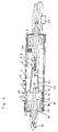
- FIG. 3 shows a slightly modified embodiment variant compared to FIG. 1.
- a ceramic gas distribution body 25 connects to the connector 10. This results in a flow-technically optimal transition from the filter into the outlet connection 16. Any deposits of particles that have not been separated are removed by the gas flow itself.
- the high-voltage bushing 26 is essentially composed of a single ceramic part, which is pressed against the honeycomb body 6 by a spring 27.
- the clamping device 14 is used only for fixing the electrode 8 in the high-voltage bushing 26.
- the side of the gas flow facing The high-voltage bushing 26 is designed as smooth as possible as half of the torus surface 28 in order to prevent the deposition of particles as much as possible.
- the high-voltage bushing 26 is sealed off from the honeycomb body 6 by a seal 29 that is resistant to high temperatures. As in the embodiment variant of FIG. 1, only a single electrical field is provided between the electrode 8 and the grounded housing 1.
- the exhaust gas flows into the filter via a laterally arranged inlet connection 30.
- a high-voltage bushing 31 is arranged in the cover 2 adjacent to this inlet connection 30, the structure of which corresponds to the high-voltage bushing 9 of FIG. 1.
- a positive high voltage is applied to the terminal 32 assigned to this high-voltage bushing 31.
- the exhaust gases flowing into the filter via the inlet connection 30 first enter the chamber 33 surrounding the high-voltage bushing 31.
- This chamber 33 is delimited by the insulating disk 13, a ceramic tube 36 and an end plate 34, which are sealed with high-temperature-resistant seals 35.
- a ceramic tube 37 is inserted, which establishes the connection to the ionization channel 7 of the honeycomb body 6.
- an electrode 38 is applied, which is connected to the connecting terminal 32 via a connecting piece 39.
- the electrode 8 protruding into the ionization channel 7 from the opposite end is connected to ground. It is thereby achieved that the spray electrodes 8 'of the electrode 8 have a negative potential difference with respect to the electrode 38 interacting with them, which is essential for the ionization.
- the housing 1 is grounded and, together with the electrode 38, builds up the electric field for the separation of the particles.
- the electrode 8 is anchored in the cover 3 via a high-voltage bushing 40 and electrically connected to ground via a regulator 41. After flowing through the separation channels 6a, the cleaned exhaust gases enter the outflow chamber 42 and leave the filter via the outlet connection 43.
- FIG. 5 shows a filter in which a series of band-shaped electrodes 44 are provided in the honeycomb body 6.
- the cover 3 is insulated with a ceramic plate 49.
- the honeycomb body 6 is insulated from the outside with a ceramic tube 50 and an insulation layer 15.
- the basic structure of the ceramic honeycomb body 6 can be seen from FIG. 6.
- the illustration is valid for all the embodiment variants of FIGS. 1 to 5, but the various electrodes with the exception of the spray electrodes 8 'are not shown.
- the ceramic honeycomb body 6 has a multiplicity of channels 6a extending over its entire length, which are separated from one another by narrow webs 6b and ribs 6c arranged essentially concentrically to one another. These radially adjacent channels 6a are arranged offset in relation to one another in the circumferential direction, so that an image corresponding to a brick wall results, as can be seen in detail from the detailed illustration. In this way, the path of the electrical current is lengthened and the total electrical resistance of the ceramic body 6 is increased.
Landscapes
- Engineering & Computer Science (AREA)
- Chemical & Material Sciences (AREA)
- Chemical Kinetics & Catalysis (AREA)
- Combustion & Propulsion (AREA)
- General Engineering & Computer Science (AREA)
- Mechanical Engineering (AREA)
- Health & Medical Sciences (AREA)
- General Chemical & Material Sciences (AREA)
- Oil, Petroleum & Natural Gas (AREA)
- Analytical Chemistry (AREA)
- Environmental & Geological Engineering (AREA)
- Biomedical Technology (AREA)
- Toxicology (AREA)
- Processes For Solid Components From Exhaust (AREA)
- Electrostatic Separation (AREA)
Abstract
Description
Die Erfindung betrifft eine Vorrichtung zur Reinigung von Abgasen von Partikeln, insbesonders zur Entfernung von Rußpartikeln aus dem Abgas von luftverdichtenden Brennkraftmaschinen, mit:
- mindestens einem Ionisationskanal, zur Erzeugung negativer Ionen;
- Abscheidekanälen, die im wesentlichen parallel und vorzugsweise koaxial zum Ionisationskanal angeordnet sind, in denen die Partikel an Wänden der Abscheidekanäle angelagert und abgebrannt werden;
- Mitteln zur Erzeugung mindestens eines elektrisches Feldes quer zur Strömungsrichtung der Abgase.
- at least one ionization channel, for generating negative ions;
- Separation channels, which are arranged essentially parallel and preferably coaxial to the ionization channel, in which the particles are deposited on the walls of the separation channels and burned off;
- Means for generating at least one electric field transverse to the flow direction of the exhaust gases.
Durch die immer strengeren Emissionsbeschränkungen gewinnt das Problem der Entfernung von Rußpartikeln aus Abgasen immer größere Bedeutung. Insbesonders für Dieselmotore ist die Frage der Partikelemission von entscheidendem Interesse.Due to the ever stricter emission restrictions, the problem of removing soot particles from exhaust gases is becoming increasingly important. The question of particle emission is of crucial interest, especially for diesel engines.
Aus der EP-A 332 609 ist ein Verfahren zur Abscheidung und Verbrennung von Rußpartikeln aus Dieselabgasen bekannt, bei dem die Gase zunächst eine Entladungsstrecke durchlaufen und dann durch die Kanäle eines Keramikkörpers strömen, in dem die Abscheidung und Verbrennung der Rußpartikel stattfindet. Ein solches Verfahren ist zwar sehr effizient, jedoch beansprucht der Filter durch die Hintereinanderanordnung von Entladungsstrecke und Abscheidestrecke relativ viel Platz. Gerade beim Einsatz in Kraftfahrzeugen ist jedoch der Bauraum zumeist sehr beschränkt.From EP-A 332 609 a method for the separation and combustion of soot particles from diesel exhaust gases is known, in which the gases first pass through a discharge path and then flow through the channels of a ceramic body in which the soot particles are separated and burned. Although such a method is very efficient, the filter takes up a relatively large amount of space due to the series arrangement of the discharge section and separating section. However, especially when used in motor vehicles, the installation space is usually very limited.
Es sind auch Verfahren bekannt, bei denen Abgase durch einen porösen Keramikkörper geführt werden, der die darin enthaltenen Partikel zurückhält. Solche Verfahren sind beispielsweise in den folgenden Druckschriften beschrieben: DE-A 36 38 203, EP-A 212 396, EP-A 270 990, GB-A 2 064 361, US-A 4,662,911. Obwohl durch verschiedene Maßnahmen für eine Entfernung oder Vernichtung der Rußpartikel vorgesorgt wird, weisen solche Filter einen unakzeptabel hohen Strömungswiderstand auf. Insbesonders im Teillastbereich kann es zur Bildung von Rußablagerungen kommen, die einen beträchtlichen Druckverlust bewirken. Solche Konzepte sehen Waben- oder Zellenfilter vor, die aus aneinanderliegenden langen Filterzellen bestehen, die vorzugsweise einen quadratischen Querschnitt besitzen und abwechselnd an der Eintrittsseite und an der Austrittsseite durch einen Pfropfen verschlossen sind. Die zu filternden Abgase können durch die zwei solcher Filterzellen gemeinsame poröse Wand hindurchtreten, während die Aerosole durch die Poren nicht hindurch können und in jener Zelle abgelagert werden, die eingangsseitig offen ist. Diese Filter sind zum Teil aus hochtemperaturfestem Keramikmaterial hergestellt und vorzugsweise mit katalytischen Substanzen beschichtet oder gedopt, sodaß es bei Sauerstoffüberschuß bereits unter 600°C zu einer Verbrennung der abgeschiedenen Rußpartikel kommt. Da diese Temperaturen nur bei Vollgasbetrieb erreicht werden, kommt es in den Perioden dazwischen zu einem erheblichen Aufbau von Gegendruck, der die Motorleistung in unangenehmer Weise reduziert. Dazu kommt eine bleibende Verlegung der Poren durch nicht brennbare metallische Verunreinigungen der Rußpartikel, sodaß es langfristig zu einem irreversiblen Aufbau von Gegendruck am Abgasfilter kommt. Darüberhinaus ergibt sich eine strukturelle Erschöpfung der ausgangsseitigen Abschlußstopfen mit der Einsatzzeit, die zu einer wachsenden Undichtheit des Filters nach längeren Einsatzzeiten führt.Methods are also known in which exhaust gases are passed through a porous ceramic body which retains the particles contained therein. Such processes are described, for example, in the following publications: DE-A 36 38 203, EP-A 212 396, EP-A 270 990, GB-
Weiters ist es bekannt, Abgase dadurch zu reinigen, daß zunächst die Rußpartikel durch Anwendung elektrischer Felder zu größerem Teilchen agglomeriert werden, die dann von einem mechanischen Abscheider, wie einem Zyklon, aus dem Abgasstrom abgetrennt werden können. Dies ist etwa in der DE-A 34 24 196 oder in der WO 85/00408 vorbeschrieben. Abgesehen davon, daß solche Vorrichtungen relativ aufwendig sind ist bei einem solchen Verfahren das Problem der Entsorgung der abgeschiedenen Rußpartikel noch nicht gelöst. Es ist inakzeptabel für den Betreiber eines Dieselfahrzeuges in kurzen Abständen Manipulationen an einem Sammelbehälter für Ruß durchführen zu müssen.It is also known to purify exhaust gases by first agglomerating the soot particles into larger particles by using electrical fields, which can then be separated from the exhaust gas stream by a mechanical separator, such as a cyclone. This is described, for example, in DE-A 34 24 196 or in WO 85/00408. Apart from the fact that such devices are relatively complex, the problem of disposing of the deposited soot particles has not yet been solved in such a method. It is unacceptable for the operator of a diesel vehicle to have to manipulate a collection container for soot at short intervals.
Ferner ist es aus der DE-A 33 24 886 bekannt, Partikel unter Ausnutzung eines elektrischen Feldes zunächst zu größeren Teilchen zu agglomerieren und dann in einen Hohlleiter einzusaugen.Furthermore, it is known from DE-A 33 24 886 to first agglomerate particles into larger particles using an electric field and then to suck them into a waveguide.
Auch hier stellt sich das Problem der endgültigen Entsorgung der abgeschiedenen Partikel. Ein Rückführung in den Ansaugstutzen des Dieselmotors ist wegen des erhöhten Verschleißes, den die Partikel hervorrufen, meist unerwünscht.The problem of the final disposal of the separated particles also arises here. A return to the intake manifold of the diesel engine is usually undesirable because of the increased wear that the particles cause.
Weiters wurde durch die DE-A 38 04 779 eine Vorrichtung zum Entfernen von Rußpartikeln aus dem Abgasstrom einer Dieselbrennkraftmaschine bekannt, bei der in einer Abgasleitung eine Rußpartikelsammelstrecke angeordnet ist. Diese besteht im wesentlichen aus einer Ionisationsstrecke, in der eine ultraviolette Lichtquelle angeordnet ist. Dieser ist eine zentrale Elektrode nachgeordnet, die von zwei konzentrischen Elektroden umgeben ist, von denen die innere mit Durchbrüchen versehen ist. Die zentrale Elektrode liegt an einem gemeinsamen Potential einer Nieder- und einer Hochspannungsquelle, von denen die erstere mit dem zweiten Pol der Niederspannungsquelle und die zweite mit dem zweiten Pol der Hochspannungsquelle verbunden ist. Im Betrieb werden die im Abgasstrom enthaltenen Rußpartikel im Bereich der Ionisationsstrecke aufgeladen und werden im Bereich der zylindrischen Elektroden aufgrund des dort herrschenden Feldes in Richtung zur zentralen Elektrode hin abgelenkt, durchdringen die innere zylinderförmige Elektrode und lagern sich an der innersten Elektrode an. Erreichen die Anlagerungen eine Höhe, bei der sie die innere zylindrische Elektrode berühren so bilden diese einen Kurzschluß für die Niederspannungsquelle und brennen ab. Der Nachteil dieser bekannten Vorrichtung liegt darin, daß es aufgrund des gegenüber der äußeren Elektrode sehr niedrigen Potentiales der inneren zylindrischen Elektrode zu einem Anlegen der Rußpartikel auch an der Außenseite dieser Elektrode kommt, wobei diese Rußpartikel aber kaum Verbrennen könnten und sich bei einer entsprechenden Dicke der Schicht aufgrund mechanischer Einflüsse, wie Vibrationen u.dgl. in größeren Flocken lösen. Um einen ausreichenden Reinigungsgrad der Abgase zu erreichen, ist es daher auch bei dieser Vorrichtung nötig einen mechanischen Abscheider, z.B. einen Zyklonabscheider nachzuordnen, wodurch sich ein entsprechend hoher konstruktiver Aufwand und ein sehr erheblicher Platzbedarf ergibt.Furthermore, DE-A 38 04 779 has disclosed a device for removing soot particles from the exhaust gas stream of a diesel internal combustion engine, in which a soot particle collection section is arranged in an exhaust gas line. This essentially consists of an ionization path in which an ultraviolet light source is arranged. This is followed by a central electrode, which is surrounded by two concentric electrodes, the inner of which is provided with openings. The central electrode is connected to a common potential of a low and a high voltage source, the first of which is connected to the second pole of the low voltage source and the second to the second pole of the high voltage source. In operation, the soot particles contained in the exhaust gas stream are charged in the area of the ionization path and are deflected in the area of the cylindrical electrodes due to the field prevailing there towards the central electrode, penetrate the inner cylindrical electrode and accumulate on the innermost electrode. If the deposits reach a height at which they touch the inner cylindrical electrode, they form a short circuit for the low-voltage source and burn off. The disadvantage of this known device is that due to the very low potential of the inner cylindrical electrode compared to the outer electrode, the soot particles also come into contact with the outside of this electrode, but these soot particles could scarcely burn and with a corresponding thickness Layer due to mechanical influences such as vibrations and the like. dissolve in larger flakes. In order to achieve a sufficient degree of purification of the exhaust gases, a mechanical separator, e.g. to arrange a cyclone separator, which results in a correspondingly high construction effort and a very considerable space requirement.
Schließlich zeigt die GB-A 411,807 eine Vorrichtung, bei der zunächst Abgasbestandteile durch elektrische Felder abgeschieden werden, um die Vergiftung des nachfolgenden Katalysators zu vermeiden. Die Entsorgung der abgeschiedenen Abgasbestandteile ist jedoch nicht geklärt.Finally, GB-A 411.807 shows a device in which exhaust gas components are first separated by electric fields in order to avoid poisoning the subsequent catalytic converter. The disposal of the separated exhaust gas components has not been clarified.
Die CH-A-372 033 betrifft in wesentlichen ein Elektrofilter. Um den Wirkungsgrad dieses Filters zu verbessern, wird das Abgas zuvor in einem Wärmetauscher gekühlt. In der DE-B-1 080 349 ist ein elektrostatischer Filter beschrieben der mit einem Schalldämpfer gekoppelt ist. Der Schalldämpfer besteht in bekannter Weise aus einer Reihe von Umlenkblechen. Aus der US-A-2 142 128 ist eine elektrische Abscheidevorrichtung bekannt, mit der in einem Gasstrom suspendierte Partikel ausgeschieden werden können. Die durch Schwerkraftwirkung abgeschiedenen Teilchen werden im Sumpf der Vorrichtung gesammelt und von dort abgezogen. Solche Vorrichtungen haben sich im Effekt als nicht effektiv erwiesen.CH-A-372 033 essentially relates to an electrostatic filter. In order to improve the efficiency of this filter, the exhaust gas is previously cooled in a heat exchanger. DE-B-1 080 349 describes an electrostatic filter which is coupled to a silencer. The muffler consists in a known manner of a series of baffles. From US-A-2 142 128 an electrical separation device is known with which particles suspended in a gas stream can be separated out. The particles separated by gravity are collected in the sump of the device and withdrawn from there. Such devices have proven ineffective in effect.
Aufgabe der Erfindung ist es, diese Nachteile zu vermeiden und ein Verfahren zu schaffen, das es in einfacher Art ermöglicht, Rußpartikel nicht nur abzuscheiden, sondern vollständig zu vernichten, wobei eine lange Standzeit bei weitgehender Wartungsfreiheit gefordert ist.The object of the invention is to avoid these disadvantages and to provide a method which, in a simple manner, makes it possible not only to separate soot particles, but also to completely destroy them, a long service life being required with largely no maintenance.
Erfindungsgemäß sind Mittel zur Umlenkung des Abgasstromes vorgesehen, die die aus dem Ionisationskanal strömenden Gase unter Umkehrung der Strömungsrichtung in die Abscheidekanäle lenken.According to the invention, means for deflecting the exhaust gas flow are provided, which direct the gases flowing out of the ionization channel into the separation channels by reversing the direction of flow.
Wesentlich ist, daß durch die Umlenkung des Gasstromes eine besonders raumsparende und die elektrische Isolation begünstigende Anordnung des Bauteile im Filter ermöglicht wird. Dies resultiert unter anderem aus der Tatsache, daß es die Umlenkung ermöglicht, die Ein- und Ausströmöffnungen relativ weit von der Hochspannungsdurchführung entfernt anzuordnen.It is essential that the deflection of the gas flow enables a particularly space-saving arrangement of the components in the filter which favors electrical insulation. This results, among other things, from the fact that the deflection enables the inflow and outflow openings to be arranged relatively far from the high-voltage bushing.
Bei einer ersten Variante der Erfindung, bei der nur ein elektrisches Feld sowohl für die Ionisation als auch für die Abscheidung vorgesehen ist, ist eine besonders einfache und kostengünstige Konstruktion des Filters möglich. Es ist dabei lediglich ein Paar von Elektroden samt Zuleitungen und Anschlüssen erforderlich. Die Spannung, die das elektrische Feld erzeugt, muß jedoch wegen der doppelten Aufgabe höher gewählt werden.In a first variant of the invention, in which only one electric field is provided both for the ionization and for the deposition, a particularly simple and inexpensive construction of the filter is possible. All that is required is a pair of electrodes, including leads and connections. However, the voltage which the electric field generates must be chosen higher because of the double task.
Bei einer zweiten Ausführungsvariante mit getrennten elektrischen Feldern für die Ionisation und für die Abscheidung können diese elektrischen Felder unabhängig voneinander und optimal für ihre jeweilige Aufgabe eingestellt werden. Außerdem kann jedes Feld für sich eine relativ geringe Potentialdifferenz aufweisen.In a second embodiment variant with separate electric fields for ionization and for deposition, these electric fields can be set independently of one another and optimally for their respective task. In addition, each field can have a relatively small potential difference.
Es ist vorteilhaft, wenn die Potentialdifferenz der elektrischen Felder zwischen 3 und 30 kV, vorzugsweise zwischen 5 und 20 kV liegt. Dadurch wird ein optimaler Abscheidegrad bei beherrschbaren Bedingungen erreicht.It is advantageous if the potential difference of the electric fields is between 3 and 30 kV, preferably between 5 and 20 kV. This ensures an optimal degree of separation under manageable conditions.
Insbesonders ist es günstig für die Abscheidung, wenn die Feldstärke der elektrischen Felder zwischen 100 und 1000 V/mm, vorzugsweise zwischen 200 und 500 V/mm liegt.In particular, it is favorable for the deposition if the field strength of the electrical fields is between 100 and 1000 V / mm, preferably between 200 and 500 V / mm.
Die Langzeitwirksamkeit des erfindungsgemäßen Filters kann dadurch erheblich verbessert werden, daß zeitweise ein Katalysator in luftgetragener Form in den Abgasstrom eingebracht wird. Dies kann im einfachsten Fall betriebsmäßig durch einen mitgeführten Vorratsbehälter erfolgen, aus dem laufzeitgesteuert etwa alle 50 Betriebsstunden des Motors eine gewisse Menge des Katalysators abgegeben wird. Besonders günstig ist es jedoch, wenn der Katalysator eingebracht wird, wenn die Temperatur des Abgasstromes über eine Zeit t hinweg kleiner als A°C ist, wobei t zwischen 20 und 60 Minuten liegt und A kleiner als 500°C, vorzugsweise kleiner als 300°C ist. Gerade durch längeren Betrieb bei niedrigen Temperaturen kann eine Erneuerung der Katalysatorschicht erforderlich werden. Durch die temperaturabhängige Regelung können optimale Abscheidegrade bei niedrigen Zugabemengen des Katalysators erreicht werden.The long-term effectiveness of the filter according to the invention can be considerably improved by temporarily introducing a catalyst in an airborne form into the exhaust gas stream. In the simplest case, this can be carried out operationally by means of a storage container which is carried and from which a certain amount of the catalyst is released every 50 operating hours of the engine. However, it is particularly advantageous if the catalyst is introduced if the temperature of the exhaust gas stream is less than A ° C. over a time t, t being between 20 and 60 minutes and A being less than 500 ° C., preferably less than 300 ° C is. Long-term operation at low temperatures may make it necessary to renew the catalyst layer. The temperature-dependent control enables optimum degrees of separation to be achieved with low additions of the catalyst.
Besonders geringe Druckverluste werden dadurch ermöglicht, daß sowohl der Ionisationskanal als auch die Abscheidekanäle als beidseitig offene Kanäle in einem einzelnen Keramikkörper angeordnet sind.Particularly low pressure losses are made possible in that both the ionization channel and the separation channels are arranged as channels open on both sides in a single ceramic body.
Es ist besonders günstig, wenn der Keramikkörper aus einem im wesentlichen gasdichten Material besteht. Dadurch sind die Strömungswege des Abgases wohldefiniert und berechenbar.It is particularly favorable if the ceramic body consists of an essentially gastight material. As a result, the flow paths of the exhaust gas are well-defined and predictable.
Vorzugsweise ist der Keramikkörper im wesentlichen zylindrisch aufgebaut, wobei der Ionisationskanal im Bereich der Zylinderachse angeordnet ist und die Abscheidekanäle um den Ionisationskanal angeordnet sind. Ein solcher Filter kann in den Abmessungen eines herkömmlichen Auspufftopfes hergestellt werden.The ceramic body is preferably of essentially cylindrical construction, the ionization channel being arranged in the region of the cylinder axis and the deposition channels being arranged around the ionization channel. Such a filter can be made in the dimensions of a conventional muffler.
Um möglichst wenig elektrische Energie für die Abscheidung zu benötigen ist es erforderlich, daß möglichst geringe Ströme durch die Stege des Keramikkörpers zwischen den Abscheidekanälen fließen.Da die Dicke dieser Stege nicht beliebig klein ausgeführt werden kann, muß man die Abscheidekanäle möglichst breit ausführen. Es ist daher günstig, wenn die Abscheidekanäle einen im wesentlichen rechteckigen Querschnitt aufweisen, wobei die längere Seite quer zur Richtung des elektrischen Feldes orientiert ist und wobei das Verhältnis zwischen Länge und Breite zwischen 4:1 und 10:1 beträgt.In order to use as little electrical energy as possible for the deposition, it is necessary for the lowest possible currents to flow through the webs of the ceramic body between the deposition channels. It is therefore expedient if the deposition channels have an essentially rectangular cross section, the longer side being oriented transversely to the direction of the electrical field and the ratio between length and width being between 4: 1 and 10: 1.
Eine weitere Verringerung der durch den Keramikkörper fließenden elektrischen Ströme kann durch die Verlängerung der Wege erreicht werden, die diese im keramischen Wabenkörper zurücklegen müssen. Vorzugsweise sind daher die Abscheidekanäle zueinander versetzt angeordnet.A further reduction in the electrical currents flowing through the ceramic body can be achieved by extending the paths which these have to cover in the ceramic honeycomb body. The separation channels are therefore preferably offset from one another.
Der Wirkungsgrad der Vorrichtung kann dadurch verbessert werden, daß die Wände der Abscheidekanäle mit einem Katalysator beschichtet sind, der die Oxidation von Kohlenwasserstoffen begünstigt. Als Katalysatoren können in bekannter Weise Metalloxidkatalysatoren verwendet werden, wie z.B. solche auf FeO-Basis.The efficiency of the device can be improved by coating the walls of the separation channels with a catalyst which promotes the oxidation of hydrocarbons. Metal oxide catalysts can be used in a known manner as catalysts, e.g. those based on FeO.
Eine Zusatzfunktion der erfindungsgemäßen Vorrichtung wird dadurch erreicht, daß Teile der Wände der Abscheidekanäle mit einem Katalysator beschichtet sind, der die Oxidation von Kohlenwasserstoffen begünstigt und daß andere Teile der Wände der Abscheidekanäle mit einem weiteren, reduzierenden Katalysator beschichtet sind. Dies wird etwa in der Weise durchgeführt, daß die an der Innenseite des Keramikkörpers liegenden Wandflächen mit dem einen Katalysator beschichtet sind und der andere Katalysator an deren Außenseite aufgebracht ist. Der reduzierende Katalysator kann etwa Stickoxide in Stickstoff und Sauerstoff zerlegen.An additional function of the device according to the invention is achieved in that parts of the walls of the separation channels are coated with a catalyst which promotes the oxidation of hydrocarbons and in that other parts of the walls of the separation channels are coated with a further reducing catalyst. This is carried out, for example, in such a way that the wall surfaces lying on the inside of the ceramic body are coated with one catalyst and the other catalyst is applied to the outside thereof. The reducing catalyst can break down nitrogen oxides into nitrogen and oxygen.
Es können zwei Elektroden vorgesehen sein, die folgendermaßen angeordnet sind:
- Im Inneren des Ionisationskanals befindet sich eine vorzugsweise zahnscheibenförmige Sprühelektrode;
- An der äußeren Mantelfläche des Keramikkörpers ist eine an Masse geschaltete Elektrode vorgesehen.
- In the interior of the ionization channel there is a preferably toothed disk-shaped spray electrode;
- An electrode connected to ground is provided on the outer lateral surface of the ceramic body.
Dies entspricht dem Verfahren mit einem einzigen elektrischen Feld.This corresponds to the single electric field method.
Weiters können die Elektroden folgendermaßen angeordnet sein:
- Im Inneren des Ionisationskanals befindet sich eine vorzugsweise zahnscheibenförmige Sprühelektrode;
- An der Wand des Ionisationskanals befindet sich eine an Masse geschaltete Elektrode;
- Zwischen den Abscheidekanälen ist mindestens eine Feldelektrode angeordnet;
- An der äußeren Mantelfläche des Keramikkörpers ist vorzugsweise eine an Masse geschaltete Elektrode vorgesehen.
- In the interior of the ionization channel there is a preferably toothed disk-shaped spray electrode;
- An electrode connected to ground is located on the wall of the ionization channel;
- At least one field electrode is arranged between the deposition channels;
- An electrode connected to ground is preferably provided on the outer lateral surface of the ceramic body.
Diese Ausführungsvariante entspricht einem Verfahren mit zwei unabhängigen elektrischen Feldern.This embodiment variant corresponds to a method with two independent electrical fields.
Es ist günstig, wenn die Sprühelektrode und die Feldelektrode an einem gemeinsamen Potential anliegen. Dadurch ist nur eine Hochspannungdurchführung erforderlich.It is advantageous if the spray electrode and the field electrode are at a common potential. As a result, only a high-voltage bushing is required.
Weiters ist es möglich, daß die Elektroden folgendermaßen angeordnet sind:
- Im Inneren des Ionisationskanals befindet sich eine vorzugsweise zahnscheibenförmige Sprühelektrode, die im wesentlichen an Masse geschaltet ist;
- An der Wand des ionisationskanals befindet sich eine an ein positives Hochspannungspotential schaltbare Elektrode;
- In the interior of the ionization channel there is a preferably toothed disk-shaped spray electrode which is essentially connected to ground;
- On the wall of the ionization channel there is an electrode that can be switched to a positive high-voltage potential;
Auch durch diese Maßnahme ist nur eine Hochspannungdurchführung erforderlich.This measure also only requires a high-voltage bushing.
Im folgenden wird die Erfindung anhand eines in den Figuren dargestellten Ausführungsbeispieles näher erläutert.The invention is explained in more detail below on the basis of an exemplary embodiment shown in the figures.
Die Figuren zeigen:
- Fig. 1 bis Fig. 5 verschiedene Ausführungsvarianten der Erfindung im Längsschnitt;
- Fig. 6 einen Querschnitt durch einen Wabenkörper.
- Fig. 1 to 5 different embodiments of the invention in longitudinal section;
- Fig. 6 shows a cross section through a honeycomb body.
Allen Ausführungsvarianten ist gemeinsam, daß der Abgasfilter aus einem im wesentlichen zylindrischen Gehäuse 1 besteht, das an den Stirnseiten mit Deckeln 2 und 3 abgeschlossen ist. Im Inneren ist ein keramischer Wabenkörper 6 angeordnet, der in seinem Querschnitt kreisringförmig ist. Dieser keramische Wabenkörper 6 kann auch aus mehreren Kreisringsegmenten zusammengesetzt sein. Zentral im Wabenkörper 6 ist der Ionisationskanal 7 angeordnet. In diesen Ionisationskanal 7 ragt die Elektrode 8, die aus einer Vielzahl von Sprühelektroden 8' zusammengesetzt ist.All the design variants have in common that the exhaust gas filter consists of an essentially
Bei der Ausführungsvariante von Fig. 1 strömt das zu reinigende Gas durch einen im Deckel 2 angeordneten Rohrstutzen 10 in den Filter. In der Verlängerung des Stutzens 10 ist ein Keramikrohr 11 vorgesehen, das an einem Ende mit einer Dichtung 12 gegenüber dem Deckel 2 abgedichtet ist. Am anderen Ende steht das Rohr 11 mit dem Ionisationskanal 7 des Wabenkörpers 6 in Verbindung.In the embodiment of FIG. 1, the gas to be cleaned flows into the filter through a
Die Elektrode 8 wird von einer Hochspannungsdurchführung 9 gehalten, die zur Isolierung der Hochspannung führenden Teile gegenüber dem geerdeten Gehäuse 1 samt Deckel 3 dient. Die Hochspannungsdurchführung 9 besteht aus drei keramischen Teilen 9a, 9b und 9c. Der Teil 9a umschließt den Schaft 8a der Elektrode 8 und ist an seinem Umfang mit Rippen ausgestattet, um die Kriechwege des Stroms zu verlängern. Den Teil 9a teilweise umgebend ist der becherförmige Teil 9b vorgesehen, der auch mit Rippen versehen ist. In diesem Teil werden die Gase umgelenkt, sodaß sie weiter durch die Abscheidekanäle 6a strömen. Über Schultern stützen sich die Teile 9a und 9b am Deckel 3 ab, wobei noch eine Isolierscheibe 13 zwischengeschaltet sein kann. Der außen angeordnete Teil 9c der Hochspannungsdurchführung 9 stützt sich auf der Außenseite des Deckels 3 ab. Eine Spannvorrichtung 14 übt eine Zugspannung auf den Schaft der Elektrode 8 aus, sodaß die Teile 9a und 9c der Hochspannungsdurchführung 9 gegeneinander verspannt werden. Die Hochspannungsdurchführung 9 ist in an sich bekannter Weise in der Art und aus dem Material gefertigt, wie dies für Hochspannungsisolatoren üblich ist.The
An der Außenseite ist der Keramikkörper 6 mit einer Isolationsschicht 15 versehen, die auch zur Abstützung gegenüber dem Gehäuse 1 dient. Ein Keramikrohr 23 im Bereich der Hochspannungsdurchführung 9 dient zusätzlich zur Isolation. Die gereinigten Abgase verlassen den Filter über einen am Umfang des Gehäuses 1 angeordneten Austrittsstutzen 16.On the outside, the
Wesentlich bei der Ausführungsvariante von Fig. 1 ist, daß nur ein elektrisches Feld erzeugt wird, das zwischen der auf ein negatives Hochspannungspotential gebrachten Elektrode 8 und dem geerdeten Gehäuse 1 aufgebaut wird. Dieses Feld dient sowohl zur Ionisierung im Ionisationskanal 7 als auch zur Abscheidung der Partikel in den Abscheidekanälen 6a.It is essential in the embodiment variant of FIG. 1 that only an electric field is generated, which is built up between the
Die Ausführungsvariante von Fig. 2 entspricht von der Konzeption im wesentlichen der oben beschriebenen Variante. Unterschiedlich ist jedoch, daß zur Ionisierung und zur Abscheidung zwei getrennte elektrische Felder vorgesehen sind.The design variant of FIG. 2 essentially corresponds to the variant described above. The difference, however, is that two separate electric fields are provided for ionization and deposition.
Das Ionisationsfeld wird zwischen der zentralen Elektrode 8 und einer an der Wand des Ionisatioskanals 7 angeordneten, geerdeten Elektrode 17 aufgebaut. Dadurch ist es möglich, die an der Elektrode 8 aufzubringende Spannung geringer als bei der ersten Ausführungsvariante zu wählen. Das Feld zur Abscheidung der Partikel wird zwischen der geerdeten Elektrode 17 und einer am äußeren Umfang des keramischen Wabenkörpers 6 angeordneten weiteren Elektrode 18 erzeugt. Diese Elektrode 18 kann auf negativem oder positivem Potential liegen. Die Isolation gegenüber dem Gehäuse 1 erfolgt über eine Keramikhülse 18 und Dichtungen 19. Die weitere Elektrode 18 wird über eine getrennte Hochspannungszuführung 21, die an einem Stutzen 22 des Gehäuses 1 angebracht ist, mit einem positiven oder negativen Hochspannungspotential gespeist. Im Bereich der Hochspannungsdurchführung 9 ist zur Isolation zusätzlich zum Keramikrohr 23 eine weitere Keramikhülse 24 vorgesehen.The ionization field is established between the
In der Fig. 3 ist eine gegenüber der Fig. 1 geringfügig modifizierte Ausführungsvariante dargestellt. An den Stutzen 10 schließt ein keramischer Gasverteilungskörper 25 an. Dieser bewirkt einen strömungstechnisch optimalen Übergang aus dem Filter in den Austrittsstutzen 16. Eventuelle Ablagerungen von nicht abgeschiedenen Partikeln werden durch die Gasströmung selbst abtransportiert. Die Hochspannungsdurchführung 26 ist im wesentlichen aus einem einzigen Keramikteil aufgebaut, der von einer Feder 27 gegen den Wabenkörper 6 gepreßt wird. Die Spannvorrichtung 14 dient nur zur Fixierung der Elektrode 8 in der Hochspannungsdurchführung 26. Die dem Gasstrom zugewendete Seite der Hochspannungsdurchführung 26 ist als halbe Torusfläche 28 möglichst glatt ausgebildet, um die Ablagerung von Partikeln möglichst zu verhindern. Partikel, die sich dennoch ablagern, werden von der Strömung, die sich an der torusförmigen Wand eng anlegt, relativ rasch abgetragen. Die Hochspannungsdurchführung 26 ist mit einer hochtemperaturfesten Dichtung 29 gegenüber dem Wabenkörper 6 abgedichtet. Wie bei der Ausführungsvariante von Fig. 1 ist zwischen der Elektrode 8 und dem geerdeten Gehäuse 1 nur ein einziges elektrisches Feld vorgesehen.3 shows a slightly modified embodiment variant compared to FIG. 1. A ceramic
In Fig. 4 ist eine weitere Variante der Erfindung dargestellt. Das Abgas strömt über einen lateral angeordneten Eintrittsstutzen 30 in den Filter. In dem diesem Eintrittsstutzen 30 benachbarten Deckel 2 ist eine Hochspannungsdurchführung 31 angeordnet, die in ihrem Aufbau der Hochspannungsdurchführung 9 von Fig. 1 entspricht. An der dieser Hochspannungsdurchführung 31 zugeordneten Anschlußklemme 32 wird jedoch eine positive Hochspannung angelegt. Die über den Eintrittsstutzen 30 in den Filter eingeströmten Abgase gelangen zunächst in die die Hochspannungsdurchführung 31 umschließende Kammer 33. Diese Kammer 33 wird von der Isolierscheibe 13, einem Keramikrohr 36 und einer Abschlußplatte 34 begrenzt, welche mit hochtemperaturfesten Dichtungen 35 abgedichtet sind. In einer Öffnung der Abschlußplatte 34 ist ein Keramikrohr 37 eingesetzt, das die Verbindung zum Ionisationskanal 7 des Wabenkörpers 6 herstellt. An der Innenseite des Ionisationskanals 7 ist eine Elektrode 38 aufgebracht, die über ein Verbindungsstück 39 mit der Anschlußklemme 32 verbunden ist. Die vom gegenüberliegenden Ende in den Ionisationskanal 7 hineinragende Elektrode 8 ist an Masse geschaltet. Dadurch wird erreicht, daß die Sprühelektroden 8' der Elektrode 8 eine negative Potentialdifferenz gegenüber der mit ihnen zusammenwirkenden Elektrode 38 aufweisen, was wesentlich für die Ionisation ist. Das Gehäuse 1 ist geerdet und baut zusammen mit der Elektrode 38 das elektrische Feld für die Abscheidung der Partikel auf. Die Elektrode 8 ist über eine Hochspannungsdurchführung 40 im Deckel 3 verankert und elektrisch über einen Regler 41 mit Masse verbunden. Die gereinigten Abgase gelangen nach dem Durchströmen der Abscheidekanäle 6a in die Ausströmkammer 42 und verlassen den Filter über den Austrittsstutzen 43.4 shows a further variant of the invention. The exhaust gas flows into the filter via a laterally arranged
In der Fig. 5 ist ein Filter dargestellt, bei dem im Wabenkörper 6 eine Reihe von bandförmigen Elektroden 44 vorgesehen sind.5 shows a filter in which a series of band-shaped
Diese sind über eine in einer Stütze 45 vorgesehenen Verbindung 46 elektrisch mit der Elektrode 8 verbunden, die auf negativem Potential liegt. Die Stütze 45 ist im Keramikrohr 11 verankert. Im Bereich des Ionisationskanals 7 ist eine weitere, an Masse liegende Elektrode 47 vorgesehen. Weiters kann im äußeren Bereich des Wabenkörpers 6 eine an Masse liegende Elektrode 48 angeordnet sein. Es ist jedoch offensichtlich, daß auch das Gehäuse 1 die Aufgabe dieser Elektrode 48 übernehmen kann. Durch die relativ kleinen Abstände zwischen den Elektroden kann bei dieser Ausführungsvariante schon mit relativ geringen Spannungen von 8 bis 12 kV das Auslangen gefunden werden. Dadurch kann auch die Hochspannungsdurchführung 9 sehr einfach aufgebaut sein. Der Deckel 3 ist mit einer Keramikplatte 49 isoliert. Nach außen ist der Wabenkörper 6 mit einem Keramikrohr 50 und einer Isolationsschicht 15 isoliert.These are electrically connected to the
Aus der Fig. 6 ist der prinzipielle Aufbau des keramischen Wabenkörpers 6 zu ersehen. Die Darstellung ist für alle Ausführungsvarianten der Fig. 1 bis 5 gültig, wobei jedoch die diversen Elektroden mit Ausnahme der Sprühelektroden 8' nicht dargestellt sind. Der keramische Wabenkörper 6 weist eine Vielzahl von über dessen gesamte Länge durchgehenden Kanälen 6a auf, die durch schmale Stege 6b und im wesentlichen konzentriscn zueinander angeordnete Rippen 6c voneinander getrennt sind. Diese radial aneinander angrenzenden Kanäle 6a sind in Umfangsrichtung gegeneinander versetzt angeordnet, sodaß sich ein einer Ziegelmauer entsprechendes Bild ergibt, wie dies ausschnittweise aus der Detaildarstellung zu ersehen ist. So wird der Weg des elektrischen Stromes verlängert und der elektrische Gesamtwiderstand des Keramikkörpers 6 vergrößert.The basic structure of the
Claims (18)
- Device for removing particles from exhaust gases, particularly for removing soot particles from the exhaust gas of air-compressing internal combustion engines, with:- at least one ionising duct (7) for generating negative ions;- separator ducts (6a) disposed substantially parallel to and preferably coaxial with the ionising duct (7), and in which the particles are deposited on walls of the separator ducts (6a) and are burned off;- means for generating at least one electrical field transversely to the flow direction of the exhaust gases;characterised in that means (9b; 28; 49) for deflecting the flow of exhaust gas are provided, which guide the gases flowing out of the ionising duct (7), reversing the flow direction into the separator ducts (6a).
- Device according to claim 1, characterised in that electrodes (8) for generating a single electrical field are provided, whose field lines pass through both the ionising duct (7) and the separator ducts (6a).
- Device according to claim 1, characterised in that electrodes (8, 44, 47, 48) for generating two electrical fields are provided, of which one passes through the ionising duct (7) and the other the separator ducts (6a).
- Device according to one of claims 1 to 3, characterised in that the potential difference of the electrical fields lies between 3 and 30 kV, preferably between 5 and 20 kV.
- Device according to one of claims 1 to 4, characterised in that the field strength of the electrical fields lies between 100 and 1000 V/mm, preferably between 200 and 500 V/mm.
- Device according to one of claims 1 to 5, characterised in that an arrangement is provided for introducing an air-borne catalyst, said arrangement introducing said catalyst when the temperature of the exhaust gas flow has been less than A degrees C for a period of time t, t lying between 20 and 60 minutes, and A being less than 500 degrees C, preferably less than 300 degrees C.
- Device according to one of claims 1 to 6, characterised in that both the ionising duct (7) and the separator ducts (6a) are disposed in a single ceramic member as ducts which are open at both ends.
- Device according to claim 7, characterised in that the ceramic member (6) comprises a substantially gastight material.
- Device according to one of claims 7 or 8, characterised in that the ceramic member (6) is substantially cylindrical in structure, the ionising duct (7) being located in the region of the cylinder axis, and the separator ducts (6a) being disposed around the ionising duct (7).
- Device according to one of claims 1 to 9, characterised in that the separator ducts (6a) have a substantially rectangular cross-section, the longer side being oriented transversely to the direction of the electrical field, and the ratio between length and width being between 4:1 and 10:1.
- Device according to one of claims 1 to 10, characterised in that the separator ducts (6a) are offset to one another.
- Device according to one of claims 1 to 11, characterised in that the walls of the separator ducts (6a) are coated with a catalyst which favours the oxidation of hydrocarbons.
- Device according to claim 12, characterised in that portions of the walls of the separator ducts (6a) are coated with a catalyst which favours the oxidation of hydrocarbons, and in that other portions of the walls of the separator ducts (6a) are coated with a further, reducing catalyst.
- Device according to one of claims 1 to 13, characterised in that two electrodes (8) are provided, which are disposed as follows:- in the interior of the ionising duct (7) there is located an electrode (8) preferably fitted with gearwheel-shaped emission electrodes (8');- on the outer cover surface of the ceramic member (6) there is provided an electrode, connected to earth, and which is preferably formed by the casing (1) (Fig. 1, Fig. 3);.
- Device according to one of claims 1 to 13, characterised in that the electrodes (8, 44, 47, 48) are disposed as follows:- in the interior of the ionising duct (7) there is located an electrode (8) preferably fitted with gearwheel-shaped emission electrodes (8');- on the wall of the ionising duct (7) there is located an electrode (47) connected to earth;- between the separator ducts (6a) there is located at least one field electrode (44);- on the outer cover surface of the ceramic member (6) there is preferably located an electrode (48) connected to earth (Fig. 5).
- Device according to claim 15, characterised in that the emission electrode (8) and the field electrode (44) are applied to a common potential.
- Device according to one of claims 1 to 13, characterised in that the electrodes (8, 18) are disposed as follows:- in the interior of the ionising duct (7) there is located a preferably gearwheel-shaped emission electrode (8) which is substantially connected to earth;- on the wall of the ionising duct (7) there is located an electrode (18) which may be connected to a positive high-tension potential.
- Ceramic member for a device according to one of claims 1 to 17, characterised in that an ionising duct (7) is provided centrally, and in that a plurality of separator ducts (6a) are disposed parallel to this ionising duct (7).
Applications Claiming Priority (2)
| Application Number | Priority Date | Filing Date | Title |
|---|---|---|---|
| AT937/90 | 1990-04-23 | ||
| AT93790 | 1990-04-23 |
Publications (2)
| Publication Number | Publication Date |
|---|---|
| EP0526552A1 EP0526552A1 (en) | 1993-02-10 |
| EP0526552B1 true EP0526552B1 (en) | 1993-12-29 |
Family
ID=3503273
Family Applications (1)
| Application Number | Title | Priority Date | Filing Date |
|---|---|---|---|
| EP91908758A Expired - Lifetime EP0526552B1 (en) | 1990-04-23 | 1991-04-23 | Process and device for removing particles from exhaust gases |
Country Status (5)
| Country | Link |
|---|---|
| EP (1) | EP0526552B1 (en) |
| AU (1) | AU7755491A (en) |
| DE (1) | DE59100781D1 (en) |
| ES (1) | ES2048014T3 (en) |
| WO (1) | WO1991016528A1 (en) |
Cited By (1)
| Publication number | Priority date | Publication date | Assignee | Title |
|---|---|---|---|---|
| US7514047B2 (en) | 2003-01-15 | 2009-04-07 | Toyota Jidosha Kabushiki Kaisha | Exhaust gas purifying apparatus |
Families Citing this family (9)
| Publication number | Priority date | Publication date | Assignee | Title |
|---|---|---|---|---|
| GB9218207D0 (en) * | 1992-08-27 | 1992-10-14 | Atomic Energy Authority Uk | The purification of internal combustion engine exhaust emissions |
| DE4236242A1 (en) * | 1992-10-27 | 1994-04-28 | Dornier Gmbh | Process for reducing soot particles in exhaust gas flows |
| ATA256293A (en) * | 1993-12-17 | 1998-10-15 | Fleck Carl M Dr | ELECTROFILTER FOR THE SEPARATION OF CARBON PARTICLES FROM THE EXHAUST GASES OF COMBUSTION ENGINES |
| DE19739181A1 (en) * | 1997-09-08 | 1999-03-11 | Abb Research Ltd | Discharge reactor and use of the same |
| AT409653B (en) | 1999-11-10 | 2002-10-25 | Fleck Carl M Dr | METHOD AND DEVICE FOR SEPARATING SOOT PARTICLES FROM AN EXHAUST GAS FLOW, IN PARTICULAR A DIESEL INTERNAL COMBUSTION ENGINE |
| FR2861802B1 (en) * | 2003-10-30 | 2006-01-20 | Renault Sas | ELECTRONIC DEVICE FOR CONTROLLING THE OPERATION OF AN ELECTROSTATIC FILTER PLACED IN THE EXHAUST LINE OF A MOTOR VEHICLE |
| WO2006128711A1 (en) * | 2005-06-03 | 2006-12-07 | Emitec Gesellschaft Für Emissionstechnologie Mbh | Method and device for decreasing the portion of particles in exhaust gases |
| IL182389A (en) * | 2007-04-10 | 2010-11-30 | Yefim Riskin | Method of air purification from dust and electrostatic filter |
| EP2641659A1 (en) * | 2012-03-20 | 2013-09-25 | Siemens Aktiengesellschaft | An improved wet electrostatic precipitator for cleaning fuel gas |
Family Cites Families (6)
| Publication number | Priority date | Publication date | Assignee | Title |
|---|---|---|---|---|
| FR1050120A (en) * | 1952-02-01 | 1954-01-05 | Onera (Off Nat Aerospatiale) | Dust collector |
| US4505723A (en) * | 1981-10-20 | 1985-03-19 | Efb Inc. | Filter apparatus |
| DE3324478A1 (en) * | 1983-07-07 | 1985-01-24 | Robert Bosch Gmbh, 7000 Stuttgart | DEVICE FOR CLEANING GASES |
| SE459320B (en) * | 1986-12-16 | 1989-06-26 | Thore Haraldson | EXHAUST CLEANER FOR EXHAUST GAS FROM COMBUSTION ENGINES AND COMBUSTION FACILITIES FOR SOLID AND LIQUID BREWING |
| DE3705979A1 (en) * | 1987-02-25 | 1988-09-08 | Navsat Gmbh | Exhaust gas soot filter |
| US4979364A (en) * | 1988-03-11 | 1990-12-25 | Fleck Carl M | Diesel fuel exhaust gas filter |
-
1991
- 1991-04-23 DE DE91908758T patent/DE59100781D1/en not_active Expired - Fee Related
- 1991-04-23 ES ES91908758T patent/ES2048014T3/en not_active Expired - Lifetime
- 1991-04-23 AU AU77554/91A patent/AU7755491A/en not_active Abandoned
- 1991-04-23 WO PCT/AT1991/000059 patent/WO1991016528A1/en not_active Ceased
- 1991-04-23 EP EP91908758A patent/EP0526552B1/en not_active Expired - Lifetime
Cited By (1)
| Publication number | Priority date | Publication date | Assignee | Title |
|---|---|---|---|---|
| US7514047B2 (en) | 2003-01-15 | 2009-04-07 | Toyota Jidosha Kabushiki Kaisha | Exhaust gas purifying apparatus |
Also Published As
| Publication number | Publication date |
|---|---|
| AU7755491A (en) | 1991-11-11 |
| DE59100781D1 (en) | 1994-02-10 |
| ES2048014T3 (en) | 1994-03-01 |
| WO1991016528A1 (en) | 1991-10-31 |
| EP0526552A1 (en) | 1993-02-10 |
Similar Documents
| Publication | Publication Date | Title |
|---|---|---|
| EP0537219B1 (en) | Process and device for cleaning exhaust gases | |
| EP0152623B1 (en) | Device for the removal of solid particles from combustion engine exhaust gases | |
| EP1179673B1 (en) | Device for recirculating gas in a combustion engine | |
| EP0650551A1 (en) | Method and device for removing particles from internal-combustion engine exhaust gases. | |
| DE102005013183A1 (en) | Multi-level space-efficient electrostatic collector | |
| EP0526552B1 (en) | Process and device for removing particles from exhaust gases | |
| EP2616646B1 (en) | Device for treating soot particle-containing exhaust gases | |
| DE102007020504A1 (en) | Electrostatic precipitator for diesel engine electrostatic crankcase ventilation system, has corona discharge electrode comprising axially extending hollow drum that surrounds tube, and charged particles shielded by tube | |
| DE3804779C2 (en) | ||
| EP0256325B1 (en) | Filter for eliminating soot particles, especially from a diesel engine exhaust | |
| EP2603678B1 (en) | Method and apparatus for reducing soot particles in the exhaust gas of an internal combustion engine | |
| WO2014114408A1 (en) | Device and method for treating an exhaust gas containing particles | |
| DE3323926C2 (en) | Device for purifying gases | |
| EP0715894B1 (en) | Electrostatic filter unit | |
| EP0307656A2 (en) | Coagulator for an exhaust purification device of an internal-combustion engine | |
| EP2153902B1 (en) | Electrostatic separator and heating system | |
| EP2820258B1 (en) | Device for treating a gas flow flowing radially outwards from a central area | |
| EP0885647B1 (en) | Apparatus for the dissociation of nitrogen oxides in exhaust gas from combustion engines | |
| AT395827B (en) | Process for burning aerosols, especially soot, contained in waste gases | |
| DE3627734C2 (en) | ||
| DE3936421A1 (en) | Successive sections of ceramic exhaust pipe collecting soot - for burning off soot, operates electrically, electrostatically or magnetically to catalytically purify fumes | |
| DE3902812C1 (en) | Electrostatic precipitator for the removal of particulates from the exhaust of internal-combustion devices or internal combustion engines and the catalytically initiated combustion of said particulates by means of an electric heating device | |
| DE202012100052U1 (en) | Arrangement of a heatable electrode in a chimney or an exhaust duct | |
| DE102024102234A1 (en) | Electrostatic condensate separator, electrostatically enhanced condensation system and process for electrostatic condensation separation | |
| DE102006026372B4 (en) | Emission control device for fuel assemblies |
Legal Events
| Date | Code | Title | Description |
|---|---|---|---|
| PUAI | Public reference made under article 153(3) epc to a published international application that has entered the european phase |
Free format text: ORIGINAL CODE: 0009012 |
|
| 17P | Request for examination filed |
Effective date: 19921022 |
|
| AK | Designated contracting states |
Kind code of ref document: A1 Designated state(s): DE ES FR GB IT SE |
|
| 17Q | First examination report despatched |
Effective date: 19920301 |
|
| GRAA | (expected) grant |
Free format text: ORIGINAL CODE: 0009210 |
|
| AK | Designated contracting states |
Kind code of ref document: B1 Designated state(s): DE ES FR GB IT SE |
|
| GBT | Gb: translation of ep patent filed (gb section 77(6)(a)/1977) |
Effective date: 19940111 |
|
| REF | Corresponds to: |
Ref document number: 59100781 Country of ref document: DE Date of ref document: 19940210 |
|
| ITF | It: translation for a ep patent filed | ||
| REG | Reference to a national code |
Ref country code: ES Ref legal event code: FG2A Ref document number: 2048014 Country of ref document: ES Kind code of ref document: T3 |
|
| ET | Fr: translation filed | ||
| PLBE | No opposition filed within time limit |
Free format text: ORIGINAL CODE: 0009261 |
|
| STAA | Information on the status of an ep patent application or granted ep patent |
Free format text: STATUS: NO OPPOSITION FILED WITHIN TIME LIMIT |
|
| 26N | No opposition filed | ||
| EAL | Se: european patent in force in sweden |
Ref document number: 91908758.5 |
|
| PGFP | Annual fee paid to national office [announced via postgrant information from national office to epo] |
Ref country code: SE Payment date: 19970318 Year of fee payment: 7 |
|
| PGFP | Annual fee paid to national office [announced via postgrant information from national office to epo] |
Ref country code: ES Payment date: 19970415 Year of fee payment: 7 |
|
| PGFP | Annual fee paid to national office [announced via postgrant information from national office to epo] |
Ref country code: GB Payment date: 19970423 Year of fee payment: 7 |
|
| PGFP | Annual fee paid to national office [announced via postgrant information from national office to epo] |
Ref country code: FR Payment date: 19970428 Year of fee payment: 7 |
|
| PGFP | Annual fee paid to national office [announced via postgrant information from national office to epo] |
Ref country code: DE Payment date: 19970528 Year of fee payment: 7 |
|
| PG25 | Lapsed in a contracting state [announced via postgrant information from national office to epo] |
Ref country code: GB Free format text: LAPSE BECAUSE OF NON-PAYMENT OF DUE FEES Effective date: 19980423 |
|
| PG25 | Lapsed in a contracting state [announced via postgrant information from national office to epo] |
Ref country code: SE Free format text: LAPSE BECAUSE OF NON-PAYMENT OF DUE FEES Effective date: 19980424 Ref country code: ES Free format text: LAPSE BECAUSE OF EXPIRATION OF PROTECTION Effective date: 19980424 |
|
| PG25 | Lapsed in a contracting state [announced via postgrant information from national office to epo] |
Ref country code: FR Free format text: THE PATENT HAS BEEN ANNULLED BY A DECISION OF A NATIONAL AUTHORITY Effective date: 19980430 |
|
| GBPC | Gb: european patent ceased through non-payment of renewal fee |
Effective date: 19980423 |
|
| EUG | Se: european patent has lapsed |
Ref document number: 91908758.5 |
|
| PG25 | Lapsed in a contracting state [announced via postgrant information from national office to epo] |
Ref country code: DE Free format text: LAPSE BECAUSE OF NON-PAYMENT OF DUE FEES Effective date: 19990202 |
|
| REG | Reference to a national code |
Ref country code: FR Ref legal event code: ST |
|
| REG | Reference to a national code |
Ref country code: ES Ref legal event code: FD2A Effective date: 20000301 |
|
| PG25 | Lapsed in a contracting state [announced via postgrant information from national office to epo] |
Ref country code: IT Free format text: LAPSE BECAUSE OF NON-PAYMENT OF DUE FEES;WARNING: LAPSES OF ITALIAN PATENTS WITH EFFECTIVE DATE BEFORE 2007 MAY HAVE OCCURRED AT ANY TIME BEFORE 2007. THE CORRECT EFFECTIVE DATE MAY BE DIFFERENT FROM THE ONE RECORDED. Effective date: 20050423 |