EP0526309A1 - Moteur à combustion interne à injection - Google Patents
Moteur à combustion interne à injection Download PDFInfo
- Publication number
- EP0526309A1 EP0526309A1 EP92402118A EP92402118A EP0526309A1 EP 0526309 A1 EP0526309 A1 EP 0526309A1 EP 92402118 A EP92402118 A EP 92402118A EP 92402118 A EP92402118 A EP 92402118A EP 0526309 A1 EP0526309 A1 EP 0526309A1
- Authority
- EP
- European Patent Office
- Prior art keywords
- cylinder
- cylinder head
- section
- injector
- engine according
- Prior art date
- Legal status (The legal status is an assumption and is not a legal conclusion. Google has not performed a legal analysis and makes no representation as to the accuracy of the status listed.)
- Withdrawn
Links
- 238000002347 injection Methods 0.000 title claims abstract description 8
- 239000007924 injection Substances 0.000 title claims abstract description 8
- 238000002485 combustion reaction Methods 0.000 title claims abstract description 4
- 239000000446 fuel Substances 0.000 claims abstract description 9
- 238000013016 damping Methods 0.000 claims description 2
- 238000005192 partition Methods 0.000 description 4
- 230000002411 adverse Effects 0.000 description 1
- 238000000034 method Methods 0.000 description 1
Images

Classifications
-
- F—MECHANICAL ENGINEERING; LIGHTING; HEATING; WEAPONS; BLASTING
- F02—COMBUSTION ENGINES; HOT-GAS OR COMBUSTION-PRODUCT ENGINE PLANTS
- F02M—SUPPLYING COMBUSTION ENGINES IN GENERAL WITH COMBUSTIBLE MIXTURES OR CONSTITUENTS THEREOF
- F02M55/00—Fuel-injection apparatus characterised by their fuel conduits or their venting means; Arrangements of conduits between fuel tank and pump F02M37/00
- F02M55/02—Conduits between injection pumps and injectors, e.g. conduits between pump and common-rail or conduits between common-rail and injectors
-
- F—MECHANICAL ENGINEERING; LIGHTING; HEATING; WEAPONS; BLASTING
- F01—MACHINES OR ENGINES IN GENERAL; ENGINE PLANTS IN GENERAL; STEAM ENGINES
- F01L—CYCLICALLY OPERATING VALVES FOR MACHINES OR ENGINES
- F01L1/00—Valve-gear or valve arrangements, e.g. lift-valve gear
- F01L1/26—Valve-gear or valve arrangements, e.g. lift-valve gear characterised by the provision of two or more valves operated simultaneously by same transmitting-gear; peculiar to machines or engines with more than two lift-valves per cylinder
-
- F—MECHANICAL ENGINEERING; LIGHTING; HEATING; WEAPONS; BLASTING
- F02—COMBUSTION ENGINES; HOT-GAS OR COMBUSTION-PRODUCT ENGINE PLANTS
- F02F—CYLINDERS, PISTONS OR CASINGS, FOR COMBUSTION ENGINES; ARRANGEMENTS OF SEALINGS IN COMBUSTION ENGINES
- F02F7/00—Casings, e.g. crankcases
- F02F7/006—Camshaft or pushrod housings
-
- F—MECHANICAL ENGINEERING; LIGHTING; HEATING; WEAPONS; BLASTING
- F02—COMBUSTION ENGINES; HOT-GAS OR COMBUSTION-PRODUCT ENGINE PLANTS
- F02B—INTERNAL-COMBUSTION PISTON ENGINES; COMBUSTION ENGINES IN GENERAL
- F02B2275/00—Other engines, components or details, not provided for in other groups of this subclass
- F02B2275/14—Direct injection into combustion chamber
-
- F—MECHANICAL ENGINEERING; LIGHTING; HEATING; WEAPONS; BLASTING
- F02—COMBUSTION ENGINES; HOT-GAS OR COMBUSTION-PRODUCT ENGINE PLANTS
- F02B—INTERNAL-COMBUSTION PISTON ENGINES; COMBUSTION ENGINES IN GENERAL
- F02B2275/00—Other engines, components or details, not provided for in other groups of this subclass
- F02B2275/18—DOHC [Double overhead camshaft]
-
- F—MECHANICAL ENGINEERING; LIGHTING; HEATING; WEAPONS; BLASTING
- F02—COMBUSTION ENGINES; HOT-GAS OR COMBUSTION-PRODUCT ENGINE PLANTS
- F02B—INTERNAL-COMBUSTION PISTON ENGINES; COMBUSTION ENGINES IN GENERAL
- F02B3/00—Engines characterised by air compression and subsequent fuel addition
- F02B3/06—Engines characterised by air compression and subsequent fuel addition with compression ignition
-
- F—MECHANICAL ENGINEERING; LIGHTING; HEATING; WEAPONS; BLASTING
- F02—COMBUSTION ENGINES; HOT-GAS OR COMBUSTION-PRODUCT ENGINE PLANTS
- F02F—CYLINDERS, PISTONS OR CASINGS, FOR COMBUSTION ENGINES; ARRANGEMENTS OF SEALINGS IN COMBUSTION ENGINES
- F02F1/00—Cylinders; Cylinder heads
- F02F1/24—Cylinder heads
- F02F1/42—Shape or arrangement of intake or exhaust channels in cylinder heads
- F02F1/4214—Shape or arrangement of intake or exhaust channels in cylinder heads specially adapted for four or more valves per cylinder
-
- F—MECHANICAL ENGINEERING; LIGHTING; HEATING; WEAPONS; BLASTING
- F02—COMBUSTION ENGINES; HOT-GAS OR COMBUSTION-PRODUCT ENGINE PLANTS
- F02F—CYLINDERS, PISTONS OR CASINGS, FOR COMBUSTION ENGINES; ARRANGEMENTS OF SEALINGS IN COMBUSTION ENGINES
- F02F1/00—Cylinders; Cylinder heads
- F02F1/24—Cylinder heads
- F02F2001/244—Arrangement of valve stems in cylinder heads
- F02F2001/247—Arrangement of valve stems in cylinder heads the valve stems being orientated in parallel with the cylinder axis
-
- Y—GENERAL TAGGING OF NEW TECHNOLOGICAL DEVELOPMENTS; GENERAL TAGGING OF CROSS-SECTIONAL TECHNOLOGIES SPANNING OVER SEVERAL SECTIONS OF THE IPC; TECHNICAL SUBJECTS COVERED BY FORMER USPC CROSS-REFERENCE ART COLLECTIONS [XRACs] AND DIGESTS
- Y02—TECHNOLOGIES OR APPLICATIONS FOR MITIGATION OR ADAPTATION AGAINST CLIMATE CHANGE
- Y02T—CLIMATE CHANGE MITIGATION TECHNOLOGIES RELATED TO TRANSPORTATION
- Y02T10/00—Road transport of goods or passengers
- Y02T10/10—Internal combustion engine [ICE] based vehicles
- Y02T10/12—Improving ICE efficiencies
Definitions
- the present invention relates to an internal combustion engine of the injection feed type.
- It relates in particular to a diesel engine with direct injection.
- This type of engine comprises for each cylinder a fuel injector, one end of which is connected to the pressurized fuel supply circuit by means of at least one pipe external to the cylinder block which extends outside the block. cylinder and arranged outside an adjacent portion of the cylinder head.
- the object of the present invention is to propose an engine design which makes it possible to reduce the length of the injector supply lines.
- the invention provides an engine of the type mentioned above, characterized in that a section of the supply pipe crosses the two opposite portions of the portion of the cylinder head perpendicular to the axis of rotation of the shaft. with cams.
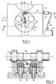
- the cylinder head 10 of a direct injection diesel engine can be seen in the figures.
- each cylinder 12 has four valves 14 whose axes 16 are parallel to the axis X-X of the cylinder 12 and are distributed regularly around this axis.
- Each cylinder is fitted with a fuel injector in the central position.
- the axis of the body of each injector 18 is therefore substantially coincident with the axis X-X of the associated cylinder.
- the cylinder head is here produced in a main cylinder block 20 on which two independent upper portions 22 and 24 are attached.
- the two portions 22 and 24 each receive a camshaft 26 and 28 respectively whose axes of rotation Y-Y are mutually parallel and perpendicular to the axis X-X of the associated cylinder.
- Each upper portion 22, 24 of the cylinder head is equipped with a cylinder head cover 30, 32.
- each camshaft controls the valves 16, for example by means of latches 34 and hydraulic slack adjusters 36.
- the two upper portions 22 and 24 of the cylinder head 10 define between them a central passage 38 in which the upper end 40 of the injector 18 is located.
- the injector 18 is connected to a pressurized fuel supply circuit 42 via a line 44.
- the circuit 42 comprises in particular an injection pump 45 which is generally mounted and driven in rotation on an axis parallel to the axis of the engine crankshaft and which is fixed to the cylinder block.
- a substantially straight section 46 of the pipe 44 passes right through the upper portion 22 of the cylinder head of the engine.
- the rectilinear section 46 is connected to the circuit 42 by a connector of known type 48 and it crosses the opposite partitions 50 and 52 of the upper portion 22 of the cylinder head through holes 54 and 56 formed respectively in the partitions 50 and 52.
- each of the holes 54 and 56 is equipped with an O-ring seal 58 as well as a ring 60 whose function is to dampen the vibrations between the pipe section 46 and partitions 50 and 52.
- the pipe section 46 extends in a direction substantially perpendicular to the axis Y-Y of the camshaft 26 and to the plane which contains the parallel axes of two consecutive cylinders 12.
- the section 46 extends substantially midway between the axes of the two consecutive cylinders, that is to say in a clear area of passage between the upper parts of the surrounding valves and in particular between the springs of these valves 16.
- the end of the pipe section 46 which opens into the central passage 38 is connected to the upper end 40 of the injector 18 by an end portion 62 of the fuel supply pipe which s 'extends substantially in the plane containing the axes of the cylinders and in a direction parallel to the axes YY of the camshafts.
- the portion 62 is connected to the section 46 by a fitting 64 of the 90 ° type of a known structure.
- the invention is not limited to the embodiment which has just been described nor to the application to the diesel engine.
- the invention also finds application in the case where the upper part of the cylinder head is produced in the form of a single element which encloses the upper end 40 of the injector, the pipe section 46 then passing only through 'a single wall of the upper portion of the cylinder head 10.
Landscapes
- Engineering & Computer Science (AREA)
- Mechanical Engineering (AREA)
- General Engineering & Computer Science (AREA)
- Chemical & Material Sciences (AREA)
- Combustion & Propulsion (AREA)
- Fuel-Injection Apparatus (AREA)
Applications Claiming Priority (2)
| Application Number | Priority Date | Filing Date | Title |
|---|---|---|---|
| FR9109896A FR2679961A1 (fr) | 1991-08-02 | 1991-08-02 | Moteur a combustion interne a injection. |
| FR9109896 | 1991-08-02 |
Publications (1)
| Publication Number | Publication Date |
|---|---|
| EP0526309A1 true EP0526309A1 (fr) | 1993-02-03 |
Family
ID=9415899
Family Applications (1)
| Application Number | Title | Priority Date | Filing Date |
|---|---|---|---|
| EP92402118A Withdrawn EP0526309A1 (fr) | 1991-08-02 | 1992-07-22 | Moteur à combustion interne à injection |
Country Status (2)
| Country | Link |
|---|---|
| EP (1) | EP0526309A1 (enExample) |
| FR (1) | FR2679961A1 (enExample) |
Cited By (1)
| Publication number | Priority date | Publication date | Assignee | Title |
|---|---|---|---|---|
| WO2022111847A1 (en) * | 2020-11-24 | 2022-06-02 | Caterpillar Shrewsbury Limited | A rocker housing for an internal combustion engine |
Citations (5)
| Publication number | Priority date | Publication date | Assignee | Title |
|---|---|---|---|---|
| US2533195A (en) * | 1946-09-23 | 1950-12-05 | Baldwin Locomotive Works | Fuel oil leakage detector for diesel engines |
| US3402703A (en) * | 1966-07-08 | 1968-09-24 | Int Harvester Co | Fuel connection to cylinder head |
| US3489435A (en) * | 1968-02-07 | 1970-01-13 | Caterpillar Tractor Co | Fuel line fitting |
| DE3128523A1 (de) * | 1981-07-18 | 1983-02-03 | Motoren-Werke Mannheim AG vorm. Benz Abt. stationärer Motorenbau, 6800 Mannheim | Zylinderkopf fuer einen verbrennungsmotor |
| US4384557A (en) * | 1981-03-18 | 1983-05-24 | Caterpillar Tractor Co. | Apparatus for draining liquid from an engine |
Family Cites Families (2)
| Publication number | Priority date | Publication date | Assignee | Title |
|---|---|---|---|---|
| FR820143A (fr) * | 1936-07-08 | 1937-11-04 | Perfectionnements aux moteurs à combustion et à explosions | |
| JPH0668254B2 (ja) * | 1986-07-09 | 1994-08-31 | 本田技研工業株式会社 | Sohc型内燃機関 |
-
1991
- 1991-08-02 FR FR9109896A patent/FR2679961A1/fr active Granted
-
1992
- 1992-07-22 EP EP92402118A patent/EP0526309A1/fr not_active Withdrawn
Patent Citations (5)
| Publication number | Priority date | Publication date | Assignee | Title |
|---|---|---|---|---|
| US2533195A (en) * | 1946-09-23 | 1950-12-05 | Baldwin Locomotive Works | Fuel oil leakage detector for diesel engines |
| US3402703A (en) * | 1966-07-08 | 1968-09-24 | Int Harvester Co | Fuel connection to cylinder head |
| US3489435A (en) * | 1968-02-07 | 1970-01-13 | Caterpillar Tractor Co | Fuel line fitting |
| US4384557A (en) * | 1981-03-18 | 1983-05-24 | Caterpillar Tractor Co. | Apparatus for draining liquid from an engine |
| DE3128523A1 (de) * | 1981-07-18 | 1983-02-03 | Motoren-Werke Mannheim AG vorm. Benz Abt. stationärer Motorenbau, 6800 Mannheim | Zylinderkopf fuer einen verbrennungsmotor |
Non-Patent Citations (2)
| Title |
|---|
| PATENT ABSTRACTS OF JAPAN vol. 10, no. 44 (M-455)21 Février 1986 & JP-A-60 195 312 ( ISUZU JIDOSHA KK ) 3 Octobre 1985 * |
| PATENT ABSTRACTS OF JAPAN vol. 13, no. 405 (M-868)7 Septembre 1989 & JP-A-11 47 156 ( KOMATSU LTD ) 8 Juin 1989 * |
Cited By (3)
| Publication number | Priority date | Publication date | Assignee | Title |
|---|---|---|---|---|
| WO2022111847A1 (en) * | 2020-11-24 | 2022-06-02 | Caterpillar Shrewsbury Limited | A rocker housing for an internal combustion engine |
| CN116490685A (zh) * | 2020-11-24 | 2023-07-25 | 卡特彼勒什鲁斯伯里有限公司 | 用于内燃机的摇臂壳体 |
| US12018612B2 (en) | 2020-11-24 | 2024-06-25 | Caterpillar Shrewsbury Limited | Rocker housing for an internal combustion engine |
Also Published As
| Publication number | Publication date |
|---|---|
| FR2679961B1 (enExample) | 1995-02-24 |
| FR2679961A1 (fr) | 1993-02-05 |
Similar Documents
| Publication | Publication Date | Title |
|---|---|---|
| US4230074A (en) | Motorcycle type internal combustion engine having optimally disposed valve actuating mechanisms | |
| US6148787A (en) | Accessory drive for engine | |
| EP0210098B1 (fr) | Culasse de moteur à combustion interne alimenté par injection | |
| FR2607553A1 (fr) | Dispositif de support pour deux arbres a cames dans la culasse d'un moteur a plusieurs cylindres en ligne | |
| FR2689937A1 (fr) | Disposition d'un appareil d'injection de carburant sur le bâti d'un moteur à combustion interne. | |
| EP0194922B1 (fr) | Dispositif d'actionnement de soupapes dans un moteur à combustion interne comportant quatre soupapes inclinées en V et une bougie centrale par cylindre | |
| JPH11148443A (ja) | 内燃機関の燃料系搭載構造 | |
| KR100304220B1 (ko) | 내연기관용커버장치 | |
| FR2711737B1 (fr) | Electrovanne sur un injecteur de carburant pour moteurs à combustion interne. | |
| US6526933B2 (en) | Multi-cylinder internal combustion engine | |
| US6561153B2 (en) | Cylinder head spark plug mounting arrangement | |
| US6223709B1 (en) | Four cycle engine | |
| JP2000104561A (ja) | 船外機 | |
| TW200424505A (en) | Knock sensor mounting structure for internal combustion engine | |
| US4748946A (en) | SOHC type internal combustion engine | |
| EP0526309A1 (fr) | Moteur à combustion interne à injection | |
| EP0293278B1 (fr) | Culasse multisoupapes pour moteur à combustion interne | |
| EP0945604B1 (fr) | Nouveau moteur à combustion interne à quatre temps, allumage commandé et injection directe | |
| JP2002276308A (ja) | 4サイクルエンジンのカム軸支持構造 | |
| JPS63143332A (ja) | 多気筒型内燃機関 | |
| JP3617173B2 (ja) | 直噴式エンジンの燃料配管構造 | |
| FR2694788A1 (fr) | Conduit d'admission pour culasse de moteur à combustion interne et procédé de réalistion. | |
| JP3116316B2 (ja) | V形エンジン用シリンダヘッド | |
| JPS62157278A (ja) | エンジンの点火装置 | |
| JP2951071B2 (ja) | 2サイクル多気筒エンジン |
Legal Events
| Date | Code | Title | Description |
|---|---|---|---|
| PUAI | Public reference made under article 153(3) epc to a published international application that has entered the european phase |
Free format text: ORIGINAL CODE: 0009012 |
|
| 17P | Request for examination filed |
Effective date: 19921212 |
|
| AK | Designated contracting states |
Kind code of ref document: A1 Designated state(s): DE GB IT |
|
| 17Q | First examination report despatched |
Effective date: 19930319 |
|
| STAA | Information on the status of an ep patent application or granted ep patent |
Free format text: STATUS: THE APPLICATION HAS BEEN WITHDRAWN |
|
| 18W | Application withdrawn |
Withdrawal date: 19930802 |