EP0525137B1 - Protective switchgear tripped by differential current or undervoltage - Google Patents
Protective switchgear tripped by differential current or undervoltage Download PDFInfo
- Publication number
- EP0525137B1 EP0525137B1 EP92903078A EP92903078A EP0525137B1 EP 0525137 B1 EP0525137 B1 EP 0525137B1 EP 92903078 A EP92903078 A EP 92903078A EP 92903078 A EP92903078 A EP 92903078A EP 0525137 B1 EP0525137 B1 EP 0525137B1
- Authority
- EP
- European Patent Office
- Prior art keywords
- switching device
- coupling member
- protective switching
- housing
- contact
- Prior art date
- Legal status (The legal status is an assumption and is not a legal conclusion. Google has not performed a legal analysis and makes no representation as to the accuracy of the status listed.)
- Expired - Lifetime
Links
Images

Classifications
-
- H—ELECTRICITY
- H01—ELECTRIC ELEMENTS
- H01H—ELECTRIC SWITCHES; RELAYS; SELECTORS; EMERGENCY PROTECTIVE DEVICES
- H01H83/00—Protective switches, e.g. circuit-breaking switches, or protective relays operated by abnormal electrical conditions otherwise than solely by excess current
- H01H83/02—Protective switches, e.g. circuit-breaking switches, or protective relays operated by abnormal electrical conditions otherwise than solely by excess current operated by earth fault currents
- H01H83/04—Protective switches, e.g. circuit-breaking switches, or protective relays operated by abnormal electrical conditions otherwise than solely by excess current operated by earth fault currents with testing means for indicating the ability of the switch or relay to function properly
-
- H—ELECTRICITY
- H01—ELECTRIC ELEMENTS
- H01H—ELECTRIC SWITCHES; RELAYS; SELECTORS; EMERGENCY PROTECTIVE DEVICES
- H01H71/00—Details of the protective switches or relays covered by groups H01H73/00 - H01H83/00
- H01H71/10—Operating or release mechanisms
- H01H71/50—Manual reset mechanisms which may be also used for manual release
- H01H71/58—Manual reset mechanisms which may be also used for manual release actuated by push-button, pull-knob, or slide
-
- H—ELECTRICITY
- H01—ELECTRIC ELEMENTS
- H01H—ELECTRIC SWITCHES; RELAYS; SELECTORS; EMERGENCY PROTECTIVE DEVICES
- H01H83/00—Protective switches, e.g. circuit-breaking switches, or protective relays operated by abnormal electrical conditions otherwise than solely by excess current
- H01H83/12—Protective switches, e.g. circuit-breaking switches, or protective relays operated by abnormal electrical conditions otherwise than solely by excess current operated by voltage falling below a predetermined value, e.g. for no-volt protection
Definitions
- the invention relates to a protective switching device for integration into a housing of an electrical connector or a mobile line step switch, wherein the protective switching device can be triggered both by differential current and by undervoltage.
- protective circuit devices of this type are connected as ballasts via one or more sensor lines to additional electrodes within the consumer. This fact requires a special connection cable between the two parts and only triggers if a fault current flows through the sensor line (s). These devices usually do not have undervoltage and free tripping and the ability to check their functionality.
- a residual current protective switching device designed as a connector for an electrical consumer which contains a switch contact arrangement which can be actuated all-pole by hand using a push button via a switching mechanism and can be triggered electromagnetically by means of electronic residual current and undervoltage monitoring. Furthermore, the device has a test facility to check its functionality.
- this known ballast uses a relatively complicated switch-on and release mechanism and accordingly has to be manufactured and assembled in a complex manner.
- the construction of the device requires the provision of a special housing.
- a protective switching device of the type mentioned in which a coupling member designed as a one-armed lever is articulated off-center by means of an operating handle, and can be guided through a locking opening in the contact carrier for switching on, the coupling member also a bevelled latching hook is pivoted against a slope formed on the contact carrier for passage through the latching opening, and the switch-on position is secured by a compression spring which is arranged between the coupling member and the contact carrier.
- a lateral triggering device is provided with a plunger anchor which, when triggered, pivots the coupling member out of engagement with the contact carrier.
- a protective switching device in which the contact carrier is pivotally mounted horizontally between two springs under prestress in the switch-off direction, the contact lever from its switch-off position, in which it is held by a lateral holding profile, by means of an electromagnetic actuable piston, which engages the holding profile, reaches its off position under the action of a compression spring.
- the invention has for its object to develop a protective switching device of the type mentioned in such a way that a compact simplified and reliable working structure is achieved.
- the switching technology of a protective switching device is based on a coupling member, which is adjustable on the operator side and is adjustable between a fixed housing stop and a pressure spring-loaded plunger armature of the electromagnetic release element, which acts on a contact carrier which is adjustable in the opposite direction via a corresponding latching profile.
- the coupling member which is designed as a two-armed pivoting lever, is pivotable about an axis in the extensions of the operating handle, which is supported on the housing against a helical compression spring.
- This coupling member is preferably provided in the actuating direction with a resiliently molded stop bracket and has a recess corresponding to the contact carrier cross section in the opposite direction above the pivot bearing point.
- the switch-on and tripping technology is preferably combined with the contact carrier to form a component, the housing of which carries the electromagnetic plunger system laterally below the above-active lever arm of the coupling member.
- the electronic device of the protective switching device it is preferably arranged together with the fixed contact pieces of the switching path, an auxiliary contact arrangement for the power supply of the device and the test button contacts on a printed circuit board, which as a further component with the above-mentioned switch-on and tripping mechanism are connected with the switching contact and with the connections the excitation winding of the electromagnetic plunger anchor system can be soldered stabilizing.
- the assembled components are installed, for example, in the housing of a conventional connector and provided with a cover penetrated by the operating handles of the protective switching device, there is also the possibility of additionally soldering the printed circuit board arranged above the switching mechanism by soldering it to the correspondingly extended connecting lugs of the connector pins inside to hold the connector housing.
- the operating handle acts through a compression spring loaded 1 manually operated switching mechanism of the two-pole protective switching device via a coupling member 4 which is elastically supported on the one hand on a fixed stop 2 of a housing part 3 and on the other hand on an armature 6 of an electromagnetic release element which is immersed in a field coil 5 against spring force.
- the coupling member 4, which is adjustable with the operating handle 1 is pivotably mounted on two downward extensions of the same about an axis 7. In its direction of actuation, the coupling member 4 is provided with a stop bracket 8 molded onto it as a spring element.
- the adjustable and pivotable coupling member 4 is provided “on the relief side” with a curve profile, in the conforming recess 11 of which the contact carrier 9 can engage in the non-pivoted state of the coupling member 4.
- the pivoting of the same as a result of manual actuation up to the stop 2 and when the plunger is energized has a latch below the contact carrier 9 and, in the case of manual relief of the operating handle 1, the adjustment of the latter and its contact pieces 10 against fixed contact pieces 13 arranged on the underside of a printed circuit board 12.
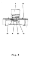
- the printed circuit board 12 also carries the electronics required for residual current monitoring, such as a specially illustrated summation current transformer 14 etc., and also an auxiliary contact arrangement 15 (according to FIG. 5) for the power supply which is closed by the coupling element 4 of the switching mechanism in the course of the activation operation of the protective switching device, and a test contact arrangement 16 to be actuated from the outside in order to be able to check its functionality.
- the electronics required for residual current monitoring such as a specially illustrated summation current transformer 14 etc.
- an auxiliary contact arrangement 15 for the power supply which is closed by the coupling element 4 of the switching mechanism in the course of the activation operation of the protective switching device, and a test contact arrangement 16 to be actuated from the outside in order to be able to check its functionality.
- the switching mechanism inserted from above into an open connector housing 17 is positively inserted into the upper part of the connector housing 17 by means of its housing part 3 and thereby extends with the magnetic yoke of the excitation coil 5 of the plunger armature system firmly attached to the housing part 3 between the extended connecting lugs of the outwardly penetrating connector pins 18 down to the bottom of the (contoured) plug-in part on the connector housing 17.
- the circuit board 12 connected to a connecting cable 19 of the protective switching device and the monitoring electronics carried by it fit into the upper part of the connector housing 17 and arrives with the fixed contact pieces 13 exactly over the movable contact pieces 10 of the switching path on both sides of the upwardly free-standing operating handle 1, and with the auxiliary contact arrangement 15 (according to FIG. 5) via the switch cam 20 provided therefor Lever arm of the coupling member 4 in the direction of the submersible anchor system.
- the same can then be soldered to the connections of the excitation coil 5 reaching through it in contact bores and to connecting lugs of plug pins 18.
- the fully assembled protective switching device can then be closed with a cover cap 21 which overlaps the opening edge of the plug housing 17 and which latches thereon and which is penetrated at the end by the operating handle 1 and a pushbutton 22 acting on the test contact arrangement 16 on the top of the printed circuit board 12.
- the protective switching device for the connected consumer is ready to be switched on after plugging it into a power supply.
- this adjusts the coupling member 4 pivotably mounted on it in the actuating direction and thus initially closes the auxiliary contact arrangement 15 for the power supply of the monitoring electronics of the device.
- the coupling member 4 rotates around it when the operating handle 1 is pressed in further Bearing shaft 7 against the plunger armature 6 inside the excitation coil 5, so that it finally hits the permanently installed magnetic core under the pressure of an armature spring.
- the procedure described above is simply reversed. Accordingly, under the pressure of its anchor spring, the plunger 6 swings the coupling member 4, which returns to the starting position with the self-resilient operating handle 1, immediately into its non-stop position and in this way prevents its latching with the contact carrier 9. When the end position is reached, the coupling member 4 then interrupts Auxiliary contact arrangement 15 and thus also switches off the monitoring electronics from the supply network.
- the excitation coil 5 is supplied with voltage via the auxiliary contact arrangement 15, so that its plunger armature 6 remains attracted.
- the suspension of the coupling member 4 through its stop bracket 8 first comes into effect and pivots the same into the latching position with the contact carrier 9, so that the latter is carried along by the more spring-loaded operating handle 1 against the force of the weaker contact opening spring until its meet two contact pieces 10 on the fixed contact pieces 13 on the underside of the printed circuit board 12, whereby the protective switching device for the consumer connected via the cable 19 is switched on and ready for operation.
- the electronic circuit arrangement carried by the printed circuit board 12 is activated by a partial current flowing to earth via the summation current transformer 14, whereby the power supply to the excitation coil 5 of the plunger armature system is interrupted and the latch between the coupling element 4 and the contact carrier 9 is opened by the latter .
- the contact opening spring presses the contact carrier 9 back into the recess 11 of the curve profile on the side of the coupling member 4 and hereby opens the switching contact path 10/13, while the operating handle 1 moves in the opposite direction back into the switch-off position.
- the version of the protective switching device presented here as an example can also be equipped with a 3-pin connection and round or flat pins of another connector system instead of the 2-pin connection arrangement.
Abstract
Description
Die Erfindung betrifft ein Schutzschaltgerät zur Integration in ein Gehäuse eines elektrischen Anschlußsteckers oder eines mobilen Leitungsschrittschalters, wobei das Schutzschaltgerät sowohl durch Differenzstrom als auch durch Unterspannung auslösbar ist.The invention relates to a protective switching device for integration into a housing of an electrical connector or a mobile line step switch, wherein the protective switching device can be triggered both by differential current and by undervoltage.
Bekannterweise werden derartige Schutzschalteinrichtungen als Vorschaltgeräte über eine oder mehrere Sensorleitungen mit zusätzlichen Elektroden innerhalb des Verbrauchers verbunden. Dieser Umstand macht ein spezielles Verbindungskabel zwischen beiden Teilen erforderlich und führt nur dann zu einer Auslösung, wenn ein Fehlerstrom über die Sensorleitung(en) fließt. Eine Unterspannungs- und Freiauslösung sowie die Möglichkeit zur Überprüfung ihrer Funktionsfähigkeit weisen diese Geräte zumeist nicht auf.As is known, protective circuit devices of this type are connected as ballasts via one or more sensor lines to additional electrodes within the consumer. This fact requires a special connection cable between the two parts and only triggers if a fault current flows through the sensor line (s). These devices usually do not have undervoltage and free tripping and the ability to check their functionality.
Aus der EP 0 189 493 B1 ist jedoch ein als Anschlußstecker für einen elektrischen Verbraucher ausgebildetes Fehlerstrom-Schutzschaltgerät bekannt, das eine Schaltkontaktanordnung enthält, die von Hand mittels Druckknopf über eine Schaltmechanik allpolig zu betätigen und durch eine elektronische Differenzstrom- und Unterspannungsüberwachung elektromagnetisch auslösbar ist. Weiterhin verfügt das Gerät über eine Prüfeinrichtung zur Kontrolle seiner Funtionsfähigkeit.From EP 0 189 493 B1, however, a residual current protective switching device designed as a connector for an electrical consumer is known which contains a switch contact arrangement which can be actuated all-pole by hand using a push button via a switching mechanism and can be triggered electromagnetically by means of electronic residual current and undervoltage monitoring. Furthermore, the device has a test facility to check its functionality.
Dieses bekannte Vorschaltgerät verwendet jedoch eine relativ komplizierte Einschalt- und Auslösemechanik und muß dementsprechend aufwendig hergestellt und montiert werden. Außerdem bedingt der konstruktive Aufbau des Geräts die Bereitstellung eines besonderen Gehäuses.However, this known ballast uses a relatively complicated switch-on and release mechanism and accordingly has to be manufactured and assembled in a complex manner. In addition, the construction of the device requires the provision of a special housing.
Aus der GB-A-2 169 749 A ist ein Schutzschaltgerät der eingangs genannten Art bekannt, bei dem mittels einer Bedienungshandhabe ein als einarmiger Hebel ausgebildetes Kopplungsglied außermittig angelenkt ist, und zum Einschalten durch eine Verriegelungsöffnung in dem Kontaktträger führbar ist, wobei das Kopplungsglied mit einem abgeschrägten Rasthaken gegen eine an dem Kontaktträger gebildete Schräge zum Durchtritt durch die Rastöffnung verschwenkt wird, und wobei die Einschaltstellung durch eine Druckfeder gesichert wird, die zwischen dem Kopplungsglied und dem Kontaktträger angeordnet ist. Für das Ausschalten ist eine seitliche Auslöseeinrichtung mit einem Tauchanker vorgesehen, der bei Auslösung das Kopplungsglied aus dem Eingriff mit dem Kontaktträger schwenkt.From GB-A-2 169 749 A a protective switching device of the type mentioned is known, in which a coupling member designed as a one-armed lever is articulated off-center by means of an operating handle, and can be guided through a locking opening in the contact carrier for switching on, the coupling member also a bevelled latching hook is pivoted against a slope formed on the contact carrier for passage through the latching opening, and the switch-on position is secured by a compression spring which is arranged between the coupling member and the contact carrier. For switching off, a lateral triggering device is provided with a plunger anchor which, when triggered, pivots the coupling member out of engagement with the contact carrier.
Aus der US-A-4 209 762 ist ein Schutzschaltgerät bekannt, bei dem der Kontaktträger waagrecht zwischen zwei Federn unter Vorspannung in Ausschaltrichtung schwenkbar gelagert ist, wobei der Kontakthebel aus seiner Ausschaltstellung, in der er durch ein seitliches Halteprofil gehalten ist, mittels eines elektromagnetisch betätigbaren Kolbens, der an das Halteprofil angreift, unter Wirkung einer Druckfeder in seine Ausschaltstellung gelangt.From US-A-4 209 762 a protective switching device is known in which the contact carrier is pivotally mounted horizontally between two springs under prestress in the switch-off direction, the contact lever from its switch-off position, in which it is held by a lateral holding profile, by means of an electromagnetic actuable piston, which engages the holding profile, reaches its off position under the action of a compression spring.
Nachteilig ist bei den vorbekannten Schaltgeräten vor allem, daß sie einen erheblichen montagetechnischen Aufwand erfordern. Demgemäß liegt der Erfindung die Aufgabe zugrunde, ein Schutzschaltgerät der eingangs genannten Gattung derart weiterzubilden, daß ein kompakter vereinfachter und zuverlässig arbeitender Aufbau erreicht wird.A disadvantage of the previously known switchgear is, above all, that they require considerable assembly outlay. Accordingly, the invention has for its object to develop a protective switching device of the type mentioned in such a way that a compact simplified and reliable working structure is achieved.
Erfindungsgemäß wird diese Aufgabe durch die in Patentanspruch 1 genannten Merkmale gelöst. Bevorzugte Merkmale, die die Erfindung vorteilhaft weiterbilden, sind in den nachgeordneten Patentansprüchen genannt.According to the invention, this object is achieved by the features mentioned in
Zur Lösung dieser Aufgabe basiert die Schaltmechnik eines erfindungsgemäßen Schutzschaltgeräts auf einem bedienungsseitig definiert zwischen einem festen Gehäuseanschlag und einem druckfederbelasteten Tauchanker des elektromagnetischen Auslöseorgans verstellbaren Kopplungsglied, das an einen in Gegenrichtung druckfederbelastet verstellbaren Kontaktträger über ein mit diesem korrespondierendes Verklinkungsprofil wirkt.To achieve this object, the switching technology of a protective switching device according to the invention is based on a coupling member, which is adjustable on the operator side and is adjustable between a fixed housing stop and a pressure spring-loaded plunger armature of the electromagnetic release element, which acts on a contact carrier which is adjustable in the opposite direction via a corresponding latching profile.
Mit der erfindungsgemäßen Ausbildung der manuell und elektronmagnetisch zu betätigenden Schaltmechanik für die elektrische Kontaktanordnung des Schutzschaltgeräts ergibt sich fortschrittlicherweise eine für sich selbständige und voll funktionsfähige Baugruppe von Einzelteilen, der sich die weiteren Teile des Geräts, - ebenso zu Baugruppen zusammengefaßt -, in engen Grenzen beiordnen lassen, um insgesamt in ein kleineres Gehäuse oder den entsprechenden Leerraum innerhalb eines beliebigen Elektrogerätes eingebaut werden zu können.With the inventive design of the manually and electronically actuated switching mechanism for the electrical contact arrangement of the protective switching device, there is progressively a self-contained and fully functional assembly of individual parts, to which the other parts of the device, also grouped together, are assigned within narrow limits to be installed in a smaller housing or the corresponding empty space within any electrical device.
Nach einer bevorzugten Ausgestaltung ist das als zweiarmiger Schwenkhebel ausgebildete Kopplungsglied um eine Achse verschwenkbar in den Fortsätzen der sich gegen eine Schraubendruckfeder am Gehäuse abstützenden Bedienungshandhabe gelagert. Dabei ist dieses Kopplungsglied vorzugsweise in Betätigungsrichtung mit einem ihm federnd angeformten Anschlagbügel versehen und weist in Gegenrichtung oberhalb der Drehlagerstelle eine dem Kontaktträgerquerschnitt entsprechende Ausnehmung auf. Bevorzugt ist die Einschalt- und Auslösemechnik mit dem Kontaktträger zu einem Bauteil zusammengefaßt, dessen Gehäuse seitlich unterhalb des vorstehend-aktiven Hebelarms des Kopplungsgliedes das elektromagnetische Tauchankersystem trägt.According to a preferred embodiment, the coupling member, which is designed as a two-armed pivoting lever, is pivotable about an axis in the extensions of the operating handle, which is supported on the housing against a helical compression spring. This coupling member is preferably provided in the actuating direction with a resiliently molded stop bracket and has a recess corresponding to the contact carrier cross section in the opposite direction above the pivot bearing point. The switch-on and tripping technology is preferably combined with the contact carrier to form a component, the housing of which carries the electromagnetic plunger system laterally below the above-active lever arm of the coupling member.
Die elektronische Einrichtung des Schutzschaltgeräts betreffend, ist diese bevorzugt mitsamt den Festkontaktstücken der Schaltstrecke, einer Hilfskontaktanordnung für die Stromversorgung des Geräts und der Prüftastenkontakte auf einer gedruckten Leiterplatte angeordnet, welche als ein weiteres Bauteil mit der vorbeschriebenen Einschalt- und Auslösemechanik schaltkontaktschlüssig zusammengesetzt und mit den Anschlüssen der Erregerwicklung des elektromagnetischen Tauchankersystems stabilisierend verlötet werden kann. - Wenn die zusammengestellten Bauteile beispielsweise in das Gehäuse eines gebräuchlichen Anschlußsteckers eingebaut und mit einer von den Bedienungshandhaben der Schutzschalteinrichtung durchgriffenen Abdeckung versehen werden, besteht außerdem die Möglichkeit, die oberhalb der Schaltmechanik angeordnete Leiterplatte zusätzlich durch Verlötung mit den entsprechend nach oben verlängerten Anschlußfahnen der Steckerstifte innerhalb des Steckergehäuses zu haltern.Regarding the electronic device of the protective switching device, it is preferably arranged together with the fixed contact pieces of the switching path, an auxiliary contact arrangement for the power supply of the device and the test button contacts on a printed circuit board, which as a further component with the above-mentioned switch-on and tripping mechanism are connected with the switching contact and with the connections the excitation winding of the electromagnetic plunger anchor system can be soldered stabilizing. - If the assembled components are installed, for example, in the housing of a conventional connector and provided with a cover penetrated by the operating handles of the protective switching device, there is also the possibility of additionally soldering the printed circuit board arranged above the switching mechanism by soldering it to the correspondingly extended connecting lugs of the connector pins inside to hold the connector housing.
In der anliegenden Zeichnung ist als Ausführungsbeispiel der Erfindung das in einen konturierten Winkelstecker eingebaute Schutzschaltgerät für den über ein Kabel angeschlossenen Verbraucher dargestellt. Dabei zeigen:
- Fig. 1
- einen Längsschnitt durch das zweipolige Gerät in der Ausschaltstellung;
- Fig. 2
- eine Teildarstellung aus Fig. 1 bei vollständig eingedrückter Bedienungshandhabe;
- Fig. 3
- die gleiche Darstellung (gem. Fig. 2) in der Einschaltstellung;
- Fig. 4
- einen Querschnitt durch das Gerät (gem. Fig. 6) im Bereich der Schaltkontaktanordnung;
- Fig. 5
- eine Teildarstellung der Hilfskontaktanordnung für die Stromversorgung der Elektronik; und
- Fig. 6
- eine Draufsicht auf das geöffnete Gerät in vereinfachter Darstellung.
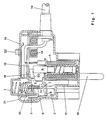
- Fig. 1
- a longitudinal section through the two-pole device in the off position;
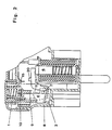
- Fig. 2
- a partial view of Figure 1 with the operating handle fully depressed.
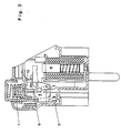
- Fig. 3
- the same representation (according to FIG. 2) in the switched-on position;
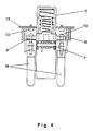
- Fig. 4
- a cross section through the device (in accordance with FIG. 6) in the area of the switch contact arrangement;
- Fig. 5
- a partial view of the auxiliary contact arrangement for the power supply of the electronics; and
- Fig. 6
- a plan view of the open device in a simplified representation.
Wie aus der schematischen Darstellung in Fig. 1 der Zeichnung ersichtlich ist, wirkt die durch eine druckfederbelastete Bedienungshandhabe 1 manuell zu betätigende Schaltmechanik des zweipoligen Schutzschaltgeräts über ein sich einerseits an einem festen Anschlag 2 eines Gehäuseteils 3 elastisch abstützende Kopplungsglied 4 und andererseits auf einen gegen Federkraft in eine Erregerspule 5 eintauchenden Anker 6 eines elektromagnetischen Auslöseorgans ein. Dabei ist das mit der Bedienungshandhabe 1 verstellbare Kopplungsglied 4 an zwei nach unten reichenden Fortsätzen derselben um eine Achse 7 schwenkbar gelagert. In seiner Betätigungsrichtung ist das Kopplungsglied 4 mit einem ihm als Federungselement angeformten Anschlagbügel 8 versehen. Zur Verklinkung mit einem in Gegenrichtung zu der Einschaltbetätigung druckfederbelastet verstellbaren Kontaktträger 9 für beweglichen Kontaktstücke 10 ist das verstell- und schwenkbare Kopplungsglied 4 "entlastungsseitig" mit einem Kurvenprofil versehen, in dessen konforme Ausnehmung 11 der Kontaktträger 9 im unverschwenkten Zustand des Kopplungsgliedes 4 eingreifen kann. Dagegen hat die Verschwenkung desselben infolge manueller Betätigung bis gegen den Anschlag 2 und bei erregtem Tauchanker gemäß der Darstellung in den Fig.n 2 und 3 der Zeichnung eine Verklinkung unterhalb des Kontaktträgers 9 und bei manueller Entlastung der Bedienungshandhabe 1 die Verstellung des letzteren und seiner Kontaktstücke 10 gegen unterseitig auf einer gedruckten Leiterplatte 12 angeordneten Festkontaktstücke 13 zur Folge.As can be seen from the schematic illustration in FIG. 1 of the drawing, the operating handle acts through a compression spring loaded 1 manually operated switching mechanism of the two-pole protective switching device via a
Als weiteres Bauteil des Schutzschaltgeräts trägt die Leiterplatte 12 außerdem die zur Differenzstromüberwachung benötigte Elektronik, wie einen besonders dargestellten Summenstromwandler 14 etc., zudem eine im Zuge der Einschaltbetätigung durch das Kopplungsglied 4 der Schaltmechanik geschlossene Hilfskontaktanordnung 15 (gem. Fig. 5) für die Stromversorgung des Schutzschaltgeräts, sowie eine von außen zu betätigende Prüfkontaktanordnung 16, um dessen Funktionsfähigkeit kontrollieren zu können.As a further component of the protective switching device, the printed
Die montagemäßige Anordnung der in Schaltmechanik und in Überwachungselektronik gegliederten Bauteile innerhalb des hier als Ausführungsbeispiel gewählten Winkelsteckers betreffend, schiebt sich die von oben in ein offene Steckergehäuse 17 eingesetzte Schaltmechanik mittels ihres Gehäuseteils 3 formschlüssig in das Oberteil des Steckergehäuses 17 ein und reicht dabei mit dem Magnetjoch der dem Gehäuseteil 3 fest angesetzten Erregerspule 5 des Tauchankersystems zwischen den verlängerten Anschlußfahnen der nach außen durchgreifenden Steckerstifte 18 bis auf den Boden des (konturierten) Einsteckteils am Steckergehäuse 17. Gemäß der Darstellung in den Fig.n 4 und 6 der Zeichnung fügt sich die mit einem Anschlußkabel 19 des Schutzschaltgeräts verbundene Leiterplatte 12 und die von ihr getragene Überwachungselektronik formgerecht in das Oberteil des Steckergehäuses 17 ein und gelangt dabei mit den Festkontaktstücken 13 exakt über die beweglichen Kontaktstücke 10 der Schaltstrecke zu beiden Seiten der nach oben freistehenden Bedienungshandhabe 1, sowie mit der Hilfskontaktanordnung 15 (gem. Fig. 5) über den dafür mit einem Schaltnocken 20 versehenen Hebelarm des Kopplungsgliedes 4 in Richtung Tauchankersystem. Zur Halterung der Leiterplatte 12 läßt sich dieselbe dann mit den sie in Kontaktbohrungen durchgreifenden Anschlüssen der Erregerspule 5 und mit Anschlußfahnen von Steckerstifte 18 verlöten. Anschließend kann man das fertigmontierte Schutzschaltgerät mit einer die Öffnungsrandung des Steckergehäuses 17 übergreifenden und an ihr verrastenden Abdeckkappe 21 verschließen, die stirnseitig von der Bedienungshandhabe 1 und einer auf die Prüfkontaktanordnung 16 an der Oberseite der Leiterplatte 12 einwirkenden Drucktaste 22 durchgriffen wird.The assembly-related arrangement of the components divided into switching mechanics and monitoring electronics within the angled connector chosen here as an exemplary embodiment, the switching mechanism inserted from above into an
In dieser Ausführung ist das Schutzschaltgerät für den angeschlossenen Verbraucher nach dem Einstecken in eine spannungsversorgte Steckdose einschaltbereit. Bei manuellem Druck auf die Bedienungshandhabe 1 verstellt diese das an ihr schwenkbar gelagerte Kopplungsglied 4 in Betätigungsrichtung und schließt damit zunächst die Hilfskontaktanordnung 15 für die Stromversorgung der Überwachungselektronik des Geräts. Wenn dann das Kopplungsglied 4 unter Einbeziehung der Federung durch seinen Anschlagbügel 8 den festen Anschlag 2 am Gehäuseteil 3 der Schaltmechanik erreicht hat, dreht sich das Kopplungsglied 4 bei weiterem Eindrücken der Bedienungshandhabe 1 um seine Lagerwelle 7 gegen den Tauchanker 6 im Inneren der Erregerspule 5, so daß dieser unter dem Druck einer Ankerfeder schließlich auf den festeingebauten Magnetkern trifft.In this version, the protective switching device for the connected consumer is ready to be switched on after plugging it into a power supply. With manual pressure on the
Bei Freigabe der Bedienungshandhabe 1 und einem vorhandenen Fehler in der Festinstallation, beispielsweise in Form einer Leiterunterbrechung, kehrt sich der vorbeschriebene Ablauf einfach um. Demgemäß schwenkt der Tauchanker 6 unter dem Druck seiner Ankerfeder das mit der eigenständig rückfedernden Bedienungshandhabe 1 in die Ausgangsstellung zurückkehrende Kopplungsglied 4 sofort in seine anschlagfreie Lage und verhindert auf diese Weise seine Verklinkung mit dem Kontaktträger 9. Bei Erreichen der Endstellung unterbricht dann das Kopplungsglied 4 die Hilfskontaktanordnung 15 und schaltet damit auch die Überwachungselektronik vom Versorgungsnetz ab.If the
Im fehlerfreien Zustand der Anlage wird die Erregerspule 5 dagegen über die Hilfskontaktanordnung 15 mit Spannung versorgt, so daß ihr Tauchanker 6 angezogen bleibt. Damit gelangt bei Entlastung der Bedienungshandhabe 1 zunächst die Abfederung des Kopplungsgliedes 4 durch seinen Anschlagbügel 8 zur Wirkung und schwenkt dasselbe in die Verklinkungsstellung mit dem Kontaktträger 9, so daß dieser von der stärker gefederten Bedienungshandhabe 1 gegen die Kraft der schwächeren Kontaktöffnungsfeder mitgenommen wird, bis seine beiden Kontaktstücke 10 auf die Festkontaktstücke 13 an der Unterseite der Leiterplatte 12 treffen, womit das Schutzschaltgerät für den über das Kabel 19 angeschlossenen Verbraucher eingeschaltet und betriebsbereit ist.In the fault-free state of the system, on the other hand, the
Im Fehlerfall wird durch einen in unzulässiger Größe zur Erde abfließenden Teilstrom über den Summenstromwandler 14 die von der Leiterplatte 12 getragene elektronische Schaltungsanordnung aktiviert, womit die Stromversorgung der Erregerspule 5 des Tauchankersystems unterbrochen und von diesem die Verklinkung zwischen dem Kopplungsglied 4 und dem Kontaktträger 9 aufgeschlagen wird. Demzufolge drückt die Kontaktöffnungsfeder den Kontaktträger 9 wieder in die Ausnehmung 11 des Kurvenprofils auf Seiten des Kopplungsgliedes 4 und öffnet hiermit die Schaltkontaktstrecke 10/13, während die Bedienungshandhabe 1 gegenläufig in die Ausschaltstellung zurückfährt.In the event of a fault, the electronic circuit arrangement carried by the printed
Zum Ausschalten des Schutzschaltgerätes genügt es, dasselbe mit seinen beiden Steckerstiften 18 einfach aus der Netzsteckdose zu ziehen oder nur kurzzeitig die Prüftaste 22 zu betätigen und dadurch einen Fehlerstrom zu simulieren, der das Schutzschaltgerät - wie bei einem Defekt - auslösen läßt und - nach dessen Beseitigung - eine erneute Wiedereinschaltung erforderlich macht.To switch off the protective switching device, it is sufficient to simply pull it out of the mains socket with its two plug pins 18 or only briefly press the
Darüber hinaus läßt sich die hier als Beispiel dargebotene Ausführung des Schutzschaltgeräts bei Bedarf an Stelle der 2-poligen Anschlußvorkehrung ebenso auch mit einem 3-poligen Anschluß und Rund- oder Flachstiften eines anderen Steckverbindungssystems ausrüsten.In addition, the version of the protective switching device presented here as an example can also be equipped with a 3-pin connection and round or flat pins of another connector system instead of the 2-pin connection arrangement.
Claims (8)
- A protective switching device for integration in a housing of an electrical connecting plug or a mobile protective circuit breaker said protective switching device being adapted to be tripped both by a differential current or by an undervoltage comprisinga sum-current transformer (14) connected to an electromagnetic tripping means (5) having a spring loaded plunger type armature (6) through which a contact assembly (10, 13) with a spring loaded contact support (9) can be opened via a coupling member (4) said coupling member (4) being displaceable by operating an operative means (1) to a fixed lateral housing stop (2) and then being rotatable further to said plunger type armature (6) to an on-position, said coupling member (4) being rotatable in an opposite direction to an off-position by tripping said plunger type armature (6)said coupling member (4) being provided with a latching-in profile having a recess (11) and said contact support (9) abutting on said latching-in profile pressure spring loaded in said on-position and being located in said recess (11) in said off-position.
- The protective switching device according to claim 1,characterized in thatsaid coupling member (4) is pivotable supported around an axle (7) formed at extensions of said operative means (1) and in that said operative means (1) supports itself against a compression spring on the housing (3, 17).
- The protective switching device according to claim 1 or 2characterized in thatsaid coupling member (4) comprises in the operative direction beneath said axle (7) a spring-stop-stay (8) formed thereto and above said axle (7) said latching-in profile having said recess (11) which corresponds in its width to the diameter of said contact support (9).
- The protective switching device according to one of the preceding claims,characterized in thatsaid coupling member (4) is formed as a two-armed lever.
- The protective switching device according to claim 4,characterized in thatsaid contact support (9) and said contact assembly (10, 13) are combined together with said tripping means (5) and said operative means (1) to a first subassembly in a housing (3, 17) which supports laterally beneath a lever arm of said coupling member (4) said tripping means with said plunger type armature (6).
- The protective switching device according to claim 5,characterized in thatfixed contacts (13) of said contact assembly are arranged together with an electronic control means, an auxiliary contact assembly (15) for current supply and test key contacts (16) on a printed circuit board (12) which can be put together as a further subassembly with said first subassembly in a closed contact and which can be soldered up with exciting winding connections of said tripping means (5).
- The protective switching device according to claim 6,characterized in thatsaid subassemblies are commonly insertable in said housing (3, 17) for example of a connecting plug or of a suspension switch or suchlike which can be closed with a cover (21) being reached through by said operative means (1) and a test key (22).
- The protective switching device according to claim 7,characterized in thatsaid circuit board (12) arranged in said housing (3, 17) is additionally supported by a soldering with corresponding elongated connecting lugs of plug pins (18).
Applications Claiming Priority (3)
| Application Number | Priority Date | Filing Date | Title |
|---|---|---|---|
| DE4105040A DE4105040C1 (en) | 1991-02-19 | 1991-02-19 | |
| DE4105040 | 1991-02-19 | ||
| PCT/DE1992/000053 WO1992015110A1 (en) | 1991-02-19 | 1992-01-25 | Protective switchgear tripped by differential current or undervoltage |
Publications (2)
| Publication Number | Publication Date |
|---|---|
| EP0525137A1 EP0525137A1 (en) | 1993-02-03 |
| EP0525137B1 true EP0525137B1 (en) | 1996-04-24 |
Family
ID=6425342
Family Applications (1)
| Application Number | Title | Priority Date | Filing Date |
|---|---|---|---|
| EP92903078A Expired - Lifetime EP0525137B1 (en) | 1991-02-19 | 1992-01-25 | Protective switchgear tripped by differential current or undervoltage |
Country Status (5)
| Country | Link |
|---|---|
| US (1) | US5347248A (en) |
| EP (1) | EP0525137B1 (en) |
| AU (1) | AU655962B2 (en) |
| DE (1) | DE4105040C1 (en) |
| WO (1) | WO1992015110A1 (en) |
Families Citing this family (19)
| Publication number | Priority date | Publication date | Assignee | Title |
|---|---|---|---|---|
| JP2590760Y2 (en) * | 1992-10-15 | 1999-02-17 | ホシデン株式会社 | Insertion plug with earth leakage cut-off mechanism |
| US6052047A (en) * | 1997-05-28 | 2000-04-18 | Eaton Corporation | Circuit interrupter with covered accessory case, adjustable under voltage relay, self-retaining collar and one-piece rail attachment |
| US6246558B1 (en) * | 1998-08-24 | 2001-06-12 | Leviton Manufacturing Company | Circuit interrupting device with reverse wiring protection |
| US6288882B1 (en) | 1998-08-24 | 2001-09-11 | Leviton Manufacturing Co., Inc. | Circuit breaker with independent trip and reset lockout |
| US7098761B2 (en) * | 1998-08-24 | 2006-08-29 | Leviton Manufacturing Co., Inc. | Reset lockout mechanism and independent trip mechanism for center latch circuit interrupting device |
| US6771152B2 (en) | 2001-03-21 | 2004-08-03 | Leviton Manufacturing Co., Inc. | Pivot point reset lockout mechanism for a ground for fault circuit interrupter |
| US6944001B2 (en) * | 1998-08-24 | 2005-09-13 | Leviton Manufacturing Co., Inc. | Circuit interrupting system with independent trip and reset lockout |
| US6982856B2 (en) * | 2001-03-21 | 2006-01-03 | Leviton Manufacturing Co., Inc. | GFCI with reset lockout |
| US7049910B2 (en) * | 1998-08-24 | 2006-05-23 | Leviton Manufacturing Co., Inc. | Circuit interrupting device with reset lockout and reverse wiring protection and method of manufacture |
| US7400477B2 (en) | 1998-08-24 | 2008-07-15 | Leviton Manufacturing Co., Inc. | Method of distribution of a circuit interrupting device with reset lockout and reverse wiring protection |
| US6040967A (en) * | 1998-08-24 | 2000-03-21 | Leviton Manufacturing Co., Inc. | Reset lockout for circuit interrupting device |
| US6437700B1 (en) | 2000-10-16 | 2002-08-20 | Leviton Manufacturing Co., Inc. | Ground fault circuit interrupter |
| US6937451B2 (en) * | 2001-03-21 | 2005-08-30 | Leviton Manufacturing Co., Inc. | ALCI with reset lockout and independent trip |
| US6864769B2 (en) * | 2001-03-19 | 2005-03-08 | Leviton Manufacturing Co., Inc. | Lockout mechanism for residual current devices |
| US7599176B1 (en) * | 2002-04-08 | 2009-10-06 | Network Appliance, Inc. | Apparatus for providing visual indication of engagement of a drive received within a drive cage |
| US7455538B2 (en) | 2005-08-31 | 2008-11-25 | Leviton Manufacturing Co., Inc. | Electrical wiring devices with a protective shutter |
| DE102006031389A1 (en) * | 2006-07-07 | 2008-01-10 | Danfoss Bauer Gmbh | lead |
| US8444309B2 (en) | 2010-08-13 | 2013-05-21 | Leviton Manufacturing Company, Inc. | Wiring device with illumination |
| US8526144B2 (en) | 2011-03-31 | 2013-09-03 | Leviton Manufacturing Company, Inc. | Reset lockout with grounded neutral test |
Family Cites Families (13)
| Publication number | Priority date | Publication date | Assignee | Title |
|---|---|---|---|---|
| DE8401104U1 (en) * | 1984-04-12 | Heinrich, Hans | Carrying device for sports and / or leisure articles for attachment to an all-terrain vehicle | |
| DE1137114B (en) * | 1961-04-20 | 1962-09-27 | Licentia Gmbh | Mechanism for automatic switch |
| US4010432A (en) * | 1975-10-22 | 1977-03-01 | General Electric Company | Electrical receptacle equipped with ground fault protection |
| US4209762A (en) * | 1978-09-08 | 1980-06-24 | Westinghouse Electric Corp. | Ground fault receptacle reset button |
| US4567456A (en) * | 1983-06-13 | 1986-01-28 | Technology Research Corporation | Resettable circuit closing device |
| DE3341874C1 (en) * | 1983-09-08 | 1984-07-19 | Schulte-Elektrotechnik GmbH & Co KG, 5880 Lüdenscheid | Switch arrangement having zero-voltage tripping |
| IE56291B1 (en) * | 1983-12-05 | 1991-06-05 | Leviton Manufacturing Co | Electric shock prevention system |
| GB2169749A (en) * | 1985-01-12 | 1986-07-16 | Ashley Accessories Ltd | Electrical outlet accessories with incorporated automatic circuit breaker |
| EP0189493B1 (en) * | 1985-01-28 | 1989-06-21 | Heinrich Kopp GmbH & Co. KG | Gfi circuit breaker in the form of a connecting plug |
| US4774484A (en) * | 1985-04-09 | 1988-09-27 | Square D Company | Auxiliary electrical contact for electromagnetic contactor |
| FR2582146A1 (en) * | 1985-05-14 | 1986-11-21 | Osmond Max | CIRCUIT BREAKER POWER SUPPLY DEVICE AND ELECTRICAL OUTLET INCORPORATING THE SAME |
| DE3937546A1 (en) * | 1989-11-10 | 1991-05-16 | Kopp Gmbh & Co Kg Heinrich | Mobile protection device for electrical load - has manual button acting simultaneously on armature and pivoted contact carrier |
| US5148344A (en) * | 1990-08-06 | 1992-09-15 | Tower Manufacturing Corporation | Appliance leakage current interrupter |
-
1991
- 1991-02-19 DE DE4105040A patent/DE4105040C1/de not_active Expired - Lifetime
-
1992
- 1992-01-25 US US07/940,889 patent/US5347248A/en not_active Expired - Fee Related
- 1992-01-25 EP EP92903078A patent/EP0525137B1/en not_active Expired - Lifetime
- 1992-01-25 WO PCT/DE1992/000053 patent/WO1992015110A1/en active IP Right Grant
- 1992-01-25 AU AU11759/92A patent/AU655962B2/en not_active Ceased
Also Published As
| Publication number | Publication date |
|---|---|
| DE4105040C1 (en) | 1992-09-24 |
| WO1992015110A1 (en) | 1992-09-03 |
| US5347248A (en) | 1994-09-13 |
| AU1175992A (en) | 1992-09-15 |
| AU655962B2 (en) | 1995-01-19 |
| EP0525137A1 (en) | 1993-02-03 |
Similar Documents
| Publication | Publication Date | Title |
|---|---|---|
| EP0525137B1 (en) | Protective switchgear tripped by differential current or undervoltage | |
| DE60125076T2 (en) | Circuit breaker with operating in vertical planes switching mechanism and toggle mechanism | |
| DE3906231B4 (en) | Circuit breaker with molded housing and additional actuation unit | |
| DE2928277C2 (en) | Combinable two-pole overcurrent circuit breaker | |
| EP0976138A1 (en) | Electromagnetic switching device | |
| DE3640009C2 (en) | ||
| EP2673792B1 (en) | Electrical switch | |
| DE60124439T2 (en) | Quick release of a circuit breaker with a guided through the magnetic circuit of a trigger electronics main conductor | |
| EP0120836A1 (en) | Electric safety switch for apparatus. | |
| EP0189493B1 (en) | Gfi circuit breaker in the form of a connecting plug | |
| DE3037355C2 (en) | Compact design circuit breaker with a trip pin | |
| DE2747784A1 (en) | ELECTRIC SAFETY DISCONNECTOR | |
| DE60011989T2 (en) | Electric toaster | |
| DE3937546C2 (en) | ||
| DE3940425C2 (en) | ||
| EP1243013B1 (en) | Simulation switch | |
| EP1737007A1 (en) | Electronic function relay | |
| DE2733837C2 (en) | Residual current circuit breaker with test button | |
| DE102005062476A1 (en) | Electronic protection relay | |
| DE4211915C2 (en) | Test button arrangement for a residual current or residual current circuit breaker | |
| AT380751B (en) | CIRCUIT BREAKER WITH FAULT CURRENT PROTECTION | |
| DE19735413A1 (en) | Magnetic release device for safety switch and circuit breaker | |
| DE3524524C2 (en) | Latching device for releasably latching switching devices in their switched-on position | |
| AT217116B (en) | Fault voltage relay | |
| AT281963B (en) | Circuit breaker |
Legal Events
| Date | Code | Title | Description |
|---|---|---|---|
| PUAI | Public reference made under article 153(3) epc to a published international application that has entered the european phase |
Free format text: ORIGINAL CODE: 0009012 |
|
| 17P | Request for examination filed |
Effective date: 19921006 |
|
| AK | Designated contracting states |
Kind code of ref document: A1 Designated state(s): BE CH FR GB IT LI NL SE |
|
| 17Q | First examination report despatched |
Effective date: 19931014 |
|
| RAP1 | Party data changed (applicant data changed or rights of an application transferred) |
Owner name: HEINRICH KOPP AG |
|
| GRAH | Despatch of communication of intention to grant a patent |
Free format text: ORIGINAL CODE: EPIDOS IGRA |
|
| GRAA | (expected) grant |
Free format text: ORIGINAL CODE: 0009210 |
|
| AK | Designated contracting states |
Kind code of ref document: B1 Designated state(s): BE CH FR GB IT LI NL SE |
|
| REG | Reference to a national code |
Ref country code: CH Ref legal event code: NV Representative=s name: HEPP, WENGER & RYFFEL AG |
|
| ET | Fr: translation filed | ||
| GBT | Gb: translation of ep patent filed (gb section 77(6)(a)/1977) |
Effective date: 19960531 |
|
| ITF | It: translation for a ep patent filed |
Owner name: MODIANO & ASSOCIATI S.R.L. |
|
| PG25 | Lapsed in a contracting state [announced via postgrant information from national office to epo] |
Ref country code: BE Effective date: 19970131 |
|
| PLBE | No opposition filed within time limit |
Free format text: ORIGINAL CODE: 0009261 |
|
| STAA | Information on the status of an ep patent application or granted ep patent |
Free format text: STATUS: NO OPPOSITION FILED WITHIN TIME LIMIT |
|
| 26N | No opposition filed | ||
| BERE | Be: lapsed |
Owner name: HEINRICH KOPP A.G. Effective date: 19970131 |
|
| PG25 | Lapsed in a contracting state [announced via postgrant information from national office to epo] |
Ref country code: NL Effective date: 19970801 |
|
| NLV4 | Nl: lapsed or anulled due to non-payment of the annual fee |
Effective date: 19970801 |
|
| PGFP | Annual fee paid to national office [announced via postgrant information from national office to epo] |
Ref country code: SE Payment date: 20010105 Year of fee payment: 10 |
|
| PGFP | Annual fee paid to national office [announced via postgrant information from national office to epo] |
Ref country code: GB Payment date: 20010124 Year of fee payment: 10 |
|
| PGFP | Annual fee paid to national office [announced via postgrant information from national office to epo] |
Ref country code: CH Payment date: 20010219 Year of fee payment: 10 |
|
| REG | Reference to a national code |
Ref country code: GB Ref legal event code: IF02 |
|
| PG25 | Lapsed in a contracting state [announced via postgrant information from national office to epo] |
Ref country code: GB Free format text: LAPSE BECAUSE OF NON-PAYMENT OF DUE FEES Effective date: 20020125 |
|
| PG25 | Lapsed in a contracting state [announced via postgrant information from national office to epo] |
Ref country code: SE Free format text: LAPSE BECAUSE OF NON-PAYMENT OF DUE FEES Effective date: 20020126 |
|
| PG25 | Lapsed in a contracting state [announced via postgrant information from national office to epo] |
Ref country code: LI Free format text: LAPSE BECAUSE OF NON-PAYMENT OF DUE FEES Effective date: 20020131 Ref country code: CH Free format text: LAPSE BECAUSE OF NON-PAYMENT OF DUE FEES Effective date: 20020131 |
|
| EUG | Se: european patent has lapsed |
Ref document number: 92903078.1 |
|
| GBPC | Gb: european patent ceased through non-payment of renewal fee |
Effective date: 20020125 |
|
| REG | Reference to a national code |
Ref country code: CH Ref legal event code: PL |
|
| PGFP | Annual fee paid to national office [announced via postgrant information from national office to epo] |
Ref country code: FR Payment date: 20050110 Year of fee payment: 14 |
|
| PG25 | Lapsed in a contracting state [announced via postgrant information from national office to epo] |
Ref country code: IT Free format text: LAPSE BECAUSE OF NON-PAYMENT OF DUE FEES;WARNING: LAPSES OF ITALIAN PATENTS WITH EFFECTIVE DATE BEFORE 2007 MAY HAVE OCCURRED AT ANY TIME BEFORE 2007. THE CORRECT EFFECTIVE DATE MAY BE DIFFERENT FROM THE ONE RECORDED. Effective date: 20050125 |
|
| PG25 | Lapsed in a contracting state [announced via postgrant information from national office to epo] |
Ref country code: FR Free format text: LAPSE BECAUSE OF NON-PAYMENT OF DUE FEES Effective date: 20060131 |
|
| REG | Reference to a national code |
Ref country code: FR Ref legal event code: ST Effective date: 20060929 |