EP0524719B1 - Computer system with alterable bootstrapping software and method therefor - Google Patents
Computer system with alterable bootstrapping software and method therefor Download PDFInfo
- Publication number
- EP0524719B1 EP0524719B1 EP92304936A EP92304936A EP0524719B1 EP 0524719 B1 EP0524719 B1 EP 0524719B1 EP 92304936 A EP92304936 A EP 92304936A EP 92304936 A EP92304936 A EP 92304936A EP 0524719 B1 EP0524719 B1 EP 0524719B1
- Authority
- EP
- European Patent Office
- Prior art keywords
- volatile memory
- computer system
- instructions
- electrically rewritable
- bootstrapping
- Prior art date
- Legal status (The legal status is an assumption and is not a legal conclusion. Google has not performed a legal analysis and makes no representation as to the accuracy of the status listed.)
- Expired - Lifetime
Links
Images

Classifications
-
- G—PHYSICS
- G06—COMPUTING OR CALCULATING; COUNTING
- G06F—ELECTRIC DIGITAL DATA PROCESSING
- G06F9/00—Arrangements for program control, e.g. control units
- G06F9/06—Arrangements for program control, e.g. control units using stored programs, i.e. using an internal store of processing equipment to receive or retain programs
- G06F9/44—Arrangements for executing specific programs
- G06F9/4401—Bootstrapping
- G06F9/4403—Processor initialisation
-
- G—PHYSICS
- G06—COMPUTING OR CALCULATING; COUNTING
- G06F—ELECTRIC DIGITAL DATA PROCESSING
- G06F9/00—Arrangements for program control, e.g. control units
- G06F9/06—Arrangements for program control, e.g. control units using stored programs, i.e. using an internal store of processing equipment to receive or retain programs
- G06F9/22—Microcontrol or microprogram arrangements
-
- G—PHYSICS
- G06—COMPUTING OR CALCULATING; COUNTING
- G06F—ELECTRIC DIGITAL DATA PROCESSING
- G06F15/00—Digital computers in general; Data processing equipment in general
- G06F15/76—Architectures of general purpose stored program computers
- G06F15/78—Architectures of general purpose stored program computers comprising a single central processing unit
- G06F15/7807—System on chip, i.e. computer system on a single chip; System in package, i.e. computer system on one or more chips in a single package
- G06F15/7814—Specially adapted for real time processing, e.g. comprising hardware timers
-
- G—PHYSICS
- G06—COMPUTING OR CALCULATING; COUNTING
- G06F—ELECTRIC DIGITAL DATA PROCESSING
- G06F11/00—Error detection; Error correction; Monitoring
- G06F11/07—Responding to the occurrence of a fault, e.g. fault tolerance
- G06F11/14—Error detection or correction of the data by redundancy in operations
- G06F11/1402—Saving, restoring, recovering or retrying
- G06F11/1415—Saving, restoring, recovering or retrying at system level
- G06F11/1417—Boot up procedures
Definitions
- the present invention relates to a computer system.
- Any computer system must have some way to begin program execution after a cold start.
- the hardware architecture of a CPU will normally provide for a "reset” operation, which places all of the hardware circuits in a known electrical state; but it is still necessary to start the CPU on execution of a desired program.
- some computer systems would be manually configured to read in a "bootstrap loader" program at startup.
- This bootstrap program was a simple program which loaded in, and started execution of, another sequence of instructions, which were the beginning of the desired program. Bootstrap programs are often referred to simply as "boot” software.
- the Intel 80x86 microprocessors after a hardware reset will always attempt to begin program execution from a specific memory address. That is, the microprocessor will read the contents of that memory location, and will attempt to execute the bits it finds there as a microprocessor instruction. Thus, if a branch (or conditional branch) instruction is found at this address, the microprocessor will continue its program execution from whatever address is specified.
- the specific memory location used by the 80x86 family is xxxFFFFOh, i.e. 16 bits below the top of the memory space. Other microprocessors may use a different starting address, but similar principles apply.
- this initial target address is the entry point for every session of use. This address is normally used to enter execution of programs which must be run every time the computer is used.
- the system performs various overhead tasks under software control. These may include surveying the system configuration, sanity checks etc.
- BIOS basic input/output system
- BIOS software provides some degree of machine-independence. However, in PC-class computers, this independence is not fully exploited by the available commercial software. Many programs bypass the BIOS software, and directly access the underlying hardware addresses or devices. See Glass, "The IBM PC BIOS", Byte, April 1989, pp. 303ff. In addition to these basic input/output routines, the "BIOS” software also includes some key pieces of overhead software, such as configuration update and the power-on-self-test (POST) routines.
- POST power-on-self-test
- the POST routines provide an extensive check for hardware integrity.
- the BIOS software will also launch the machine into the operating system software.
- BIOS software may direct program execution into DOS, Unix, PS/2, a DOS variant, or another operating system.
- DOS Unix
- PS/2 a DOS variant
- BIOS the term "BIOS” has become somewhat broader nowadays, and normally refers to this whole collection of basic system routines.
- BIOS software If the BIOS software were to become corrupted, the computer could become unusable. Thus, the BIOS software has conventionally been stored in read-only memory (ROM). When the microprocessor attempts to access the initial target address, it reads out software from the BIOS ROM.
- ROM read-only memory
- BIOS software In 1980 there was only one source for IBM-compatible BIOS software, and that was from IBM. However, during the 1980s, as IBM-compatible personal computers became more popular, modified versions of IBM-compatible BIOS ROMs were developed, and IBM compatible BIOS ROMs were offered by multiple vendors. As of 1991, BIOS software is often modified to implement system-dependent features, especially in low-power systems.
- BIOS software mean that sometimes it will be desirable to implement a BIOS upgrade. Dedicated users have successfully pried out and replaced ROM chips, but most users would not want this degree of hands-on contact.
- BIOS software Without boot software, a computer could not run any program at all. Thus, corruption of the boot software can make a computer totally unusable. Thus, for security against such corruption, personal computers have commonly been manufactured with their BIOS software in nonvolatile memory chips. However, for rapid system development and upgrading, it is desirable to be able to rapidly provide new BIOS chips, or even to upgrade existing BIOS chips. Over years, a variety of developments in semiconductor device technology have been used to reconcile these needs.
- One of the simplest nonvolatile memories is the mask ROM.
- a complex pattern of data can be permanently encoded.
- an array with polysilicon row lines accessed by row decoders, and metal column lines accessed by column decoders can have contact holes selectively etched, so that one bit of data is encoded at each row/column intersection.
- polysilicon row lines can be selectively linked to diffused column lines by metal shorting straps.
- PROM programmable read-only-memory
- PROMs are typically built using solid-state fuses (or antifuses), which will become open (or shorted) whenever a high current is driven through them.
- a high voltage e.g. 10 or 15 V
- EPROM electrically programmable read-only memory
- EPROMs are typically built using a floating-gate avalanche MOS device. This is a MOS transistor with an additional isolated thin film (the floating gate) interposed between the MOS control gate and the channel. By pumping charge into the floating gate, the effective threshold voltage of the MOS transistor can be changed, and this threshold voltage change is detected by a sense amplifier.
- the channel is typically driven hard, with a high voltage on the control gate. Secondary carrier multiplication in the channel creates hot electrons, which are attracted into the floating gate.
- a high voltage e.g.
- EPROMs normally need a package with a quartz window. EPROMs are very commonly used, since they are cheap and their timing standards are familiar. EPROMs are also referred to as UVPROMs.
- EEPROM electrically erasable programmable read-only-memory
- E 2 PROM electrically erased.
- EEPROMs like EPROMS, are typically floating-gate devices. However, in an EEPROM the write and erase operations typically use tunnelling. Thus, the programming of a conventional EEPROM requires the application of a high voltage (e.g. 15 or 20 V). Programming and erasure are typically quite slow, e.g. several milliseconds per bit. EEPROMS are less commonly used than EPROMs, since they tend to be more expensive and to require even higher voltages.
- Flash-EPROM which is electrically erasable in blocks and does not have the bit-by-bit programmability of the EEPROM.
- rewritable non-volatile memory technologies include core" memory technology used in the computers of the 1 950s and early 1960s.
- U. S. Patent No. 4430704 discloses a programmable bootstrap loader apparatus, for a computer system, including an alterable non-volatile storage memory for storing a set of instructions forming a bootstrap loader program, selected elements of the bootstrap loader program being alterable under the control of firmware means included in the alterable non-volatile storage memory.
- PATENT ABSTRACTS OF JAPAN discloses a start-up system, for a computer, which includes means for detecting damage in the main boot area of a memory which is divided into a main boot area and a sub-boot area, the system effecting start-up from the sub-boot area of the memory when damage to the main boot area is detected and, subsequently, copying the contents of the sub-boot area to the main boot area.
- U. S. Patent No. 4663707 discloses a data processing apparatus including a first non-volatile memory connected directly to a computer means for providing a first level of bootstrap data and a second non-volatile memory cotmected to the computer means through a bootstrap controller for providing a second level of bootstrap data, the data in the second non-volatile memory being alterable and the computer means including hardware means for effecting the transmission of data from the first and second memories to the computer means.
- the present invention provides a computer system as defined in claim 1 and a method as defined in claim 4.
- the computer system includes a multi-element diagnostic display for indicating the result of an operation to overwrite instructions held in the electrically rewritable first non-volatile memory and, preferably, the second non-volatile memory is an ultraviolet-erasable programmable read-only-memory (UVPROM).
- UVPROM ultraviolet-erasable programmable read-only-memory
- Flash-EPROMs or other rewritable non-volatile memories may be used for the rewritable first non-volatile memory.
- the method includes the steps of reading start-up instructions from the electrically rewritable first non-volatile memory, subjecting the read-out start-up instructions to validity checks and, when a validity check is failed, overwriting the start-up instructions held in the electrically rewritable first non-volatile memory by the start-up instructions held in the second non-volatile memory.
- both memories are mappable to the same address. Note that this causes some difficulty in writing to the electrically rewritable first memory since, if it is not in the memory map it cannot be written to. In this instance, this difficulty is avoided by mapping the core software out to RAM, and then commanding an address configuration change to access the other boot memory. If one boot memory is being copied onto the other, then the contents of the source memory must also be copied out.
- the default mapping of the boot memory address is controlled by a physical switch.
- a peripheral memory controller chip controls the mapping of the boot memory address.
- the core software can change this mapping.
- the core software copies itself out to a RAM location, and commands the microprocessor to branch into the RAM address.
- the bit to select the boot memory is then toggled, so that writes to the boot memory addresses are now directed to the other boot memory (i.e. to the boot memory which was not the source of the code being executed).
- the desired data can then be written into the target boot memory. Note that, if the source of the data is in the active boot memory, that code must be written out into RAM before the boot memory address toggle is switched.
- the starting address in the boot software is occupied by a small (and strongly protected) software core, which performs sanity checks, and also provides the needed supervisory functions for boot software upgrading and replacement.
- the disclosed computer system solves the problem of performing BIOS restoration/upgrades in-situ (i.e. without removing the FLASH boot memory ROM from the system).
- the end-user or a service technician
- the core software After any hard reset of the system, the core software detects whether the boot software is corrupted, and whether the user has entered a request for upgrade. If these conditions have occurred, the core software performs the FLASH programming from the appropriate data source.
- the core software provides for the following three classes of cases. These cases together provide coverage for all conceivable field conditions:
- the system BIOS and/or video BIOS While executing reset code from the FLASH, the system BIOS and/or video BIOS are found to have a bad checksum. In this case, power-on-self-test and booting is impossible, therefore, the boot code prompts the user to insert a diskette containing system and video BIOS code and reprograms the FLASH.
- this is done with the assistance of a small 4-character diagnostic display which is mounted directly on the system chassis. This display is referred to as SmartVu TM .
- SmartVu TM This display is referred to as SmartVu TM .
- CMOS complementary metal-oxide-semiconductor
- the boot code While executing reset code from the FLASH, the boot code detects a "CMOS" flag setting indicating a user requested upgrade.
- CMOS complementary metal-oxide-semiconductor
- the boot code then prompts the user (via SmartVu) to insert a diskette containing the upgrade system and video BIOS code.
- SmartVu When the system and video BIOS programming is successfully completed, the user is prompted (via SmartVu) to reset the system. Normal POST and boot should follow.
- the boot code While executing reset code from the UVPROM, the boot code detects that a FLASH is present and that its protected 8k boot sector is jumpered for programming. Since the UVPROM is intended as a secondary ROM device, this condition is understood as a request for FLASH programming and the entire contents of the UVPROM, including the boot code in the upper 8k sector is copied into the FLASH. When the entire FLASH is successfully programmed, the user is prompted to reset the system. If the FLASH is selected as the primary ROM device, normal POST and boot should occur from the FLASH.
- the preferred rewritable boot memory is a sector-protected Flash-EPROM.
- the sector which contains the software core is actually protected by a jumper, which must be physically moved before the software core can be overwritten. This provides additional robustness.
- the core software may have to read from floppy disk, it includes the necessary overhead routines to perform this. These routines are generally similar to the BIOS functions under INT13h.
- the first non-voltaile memory may be a mask ROM, PROM or UVPROM which holds the basic system operating instructions including the bootstrap and BIOS instructions required for system activation. Those instructions may be substantially unalterable, and the system can be activated or reactivated by placing it under the control of the first non-volatile memory
- the bootstrapping instructions held in the second non-volatile memory are such as to effect the over-writing of instructions held in the rewritable non-volatile memory by the bootstrapping instructions held in the second non-volatile memory, following a hard reset of the system.
- the rewritable non-volatile memory may be a FLASH EPROM or an electrically programmable and erasable ROM to which can be written instructions, including instructions which effect the writing of instructions from an external source to the rewritable non-volatile memory.
- instructions can be written to the rewritable non-volatile memory and the rewritable non-volatile memory can then be used as the source of activating instructions for the computer system, with the flexibility that the computer system can itself rewrite at least some of the instructions held in the rewritable non-volatile memory.
- the computer system can be returned to the operating configuration provided by the instructions held in the first non-volatile memory at any time by means of a user-operated switch, say.
- the computer system includes manually operable means which has a first setting for preventing the over-writing of instructions held in the rewritable non-volatile memory and a second setting permitting the over-writing of instructions held in the rewritable nonvolatile memory.
- the instructions are such as to make the computer system capable of writing the instructions from the second non-volatile memory to the rewritable non-volatile memory so that the instructions held in the second non-volatile memory can be readily written to the rewritable non-volatile memory.
- the computer system includes a user settable switch for selecting the second non-volatile memory as its source of bootstrapping instructions and is capable of reversing the switch setting to select the rewritable non-volatile memory as its source of activating instructions thereafter. That is, the computer system is capable of activation in accordance with the instructions held in the second non-volatile memory, following which it can write those instructions to the rewritable non-volatile memory, after which it switches control to the rewritable non-volatile memory.
- the computer system includes multi-element diagnostic display means capable of indicating the result of an operation to over-write instructions held in the rewritable non-volatile memory.
- the diagnostic display means may be a multi-character display, for example, a 4-character display linked to a sub-system for checking on whether the writing of system and video BIOS has been successful and providing an apparopriate indication.
- the method of operating the computer system includes the steps of reading bootstrapping instructions from the rewritable non-volatile memory, subjecting the bootstrapping instructions to validity checks as they are read and, when a validity check is failed, overwriting the bootstrapping instructions held in the rewritable non-volatile memory with the bootstrapping instructions held in the second non-volatile memory.
- the method for operating the computer system may comprise the steps, whenever the system has undergone a hard reset, of immediately performing the following operations in a programmable central processing unit (CPU): if the said CPU is executing software from a rewritable nonvolatile boot memory,
- CPU central processing unit
- the said CPU is executing software from a second nonvolatile boot memory which is not the same as the said rewritable nonvolatile boot memory and if the said rewritable nonvolatile memory is not currently write-protected, THEN the contents of the said rewritable non-volatile memory are overwritten with the contents of the second non-volatile boot memory.
- the method of operating the computer system may comprise the steps, whenever the system undergoes a power-up transition, of immediately performing the following operations in the system microprocessor:
- the system executes a power-on-self-test routine from the said rewritable boot memory.
- the said microprocessor is executing software from said second boot memory and if said rewritable nonvolatile memory is not currently write-protected the system copies the entire contents of the said second boot memory and overwrites the contents of the said rewritable nonvolatile boot memory, thereafter prompting the user to reboot the system.
- the system executes a power-on-self-test routine from the said second boot memory.
- the method for operating the computer system may comprise, during normal operation, the steps of:
- the said rewritable nonvolatile boot memory consists essentially of a Flash EPROM or an electrically programmable and erasible read-only-memory.
- the said second nonvolatile boot memory consists essentially of a programmable-read-only-memory which is not electrically erasable.
- Figure 1 is a flow chart which shows key of the invention.
- Fig. 2 shows a hardware configuration which permits switching between alternative boot memories in an embodiment of the invention.
- the preferred embodiment is an 80486-based EISA-bus PC system.
- General features of the EISA bus are described by Glass, "Inside EISA,” Byte magazine November 1989, pp/ 417ff, and in the EISA specification.
- General features of the Intel 80486 are described by Sartore, "The 80486: A Hardware Perspective,” Byte Magazine IBM Special Edition, Fall 1989, pp. 67ff. Further detailed background on the 80486 may be found in the "80486 Programmer's Reference” and the "80486 Hardware Reference Manual,” both available from Intel.
- the system motherboard includes a custom chip, referred to herein as the "SLOB" chip, which performs a variety of special functions. These include reset control, X-bus transceiver control, and control of the boot memories and CMOS nonvoltaile memory.
- SLOB custom chip
- the "X-bus,” or “extension bus,” is an extension of the system bus, but is not directly connected to it. Instead, data is selectably transferred from the S-bus to the system bus, or vice versa, by bidirectional transceivers.
- the X-bus is commonly used, in PC architectures, to provide easier loading requirements for a variety of devices on the motherboard.
- the software core in the presently preferred embodiment, resides in the protected 8k boot sector of a FLASH ROM or in the upper 8k of a 128k UVPROM. Selection of the primary ROM device is accomplished via a physical switch.
- FIG. 2 shows more detail of how this is implemented.
- the SLOB chip supplies chip enable (CE) signals separately to the FLASH EPROM 220 and to the UVEPROM 230 (and also to the NVRAM 240).
- An output enable line OE is connected to both boot ROMs, and address lines are also provided to both.
- a hardware switch provides a line ROMIN to the SLOB chip, to define which boot memory is the initial default target.
- the FLASH EPROM has sector-by-sector protection. (This feature is found in the 28F001B type chip available from Intel).
- one sector 220A of only 8K bytes, is dedicated to the core software. This sector is protected by a hardware jumper, so corruption of the core software is unlikely.
- the hardware To achieve automatic programming of the Flash memory from a plug-in ROM, the hardware must provide a switching mechanism that allows software to boot from one source and then toggle between sources. This switchability is also required to access EISA configuration from Flash if running BIOS out of a plug-in ROM.
- the chip referred to herein as the TRANE chip is a custom memory controller. Besides performing normal DRAM management functions, this chip also provides selection, by memory domains, of which memory areas will be cached or not.
- Figure 1 is a flow chart which schematically shows key portions of the methods used in the computer system of the presently preferred embodiment.
- Procedure 8kboot_strt is the power-on-reset entry point into the 8k boot sector code for a 128k FLASH EPROM.
- This code along with a reset vector is located in the upper 8k boot sector of a 128k FLASH EPROM.
- the reset vector will be located at 1fff0h (physical ROM address), and the start of this routine will be located at 1e000h (start.of the 8k boot sector).
- the reset vector will contain a NEAR jmp to this code, so execution will start in processor real mode, ROM native mode, at logical address 0ffffe000h.
- This procedure implements most of the steps in the flow chart of Figure 1. Specifically, this procedure:
- Procedure bootFlash contains the 8K power-on logic executed when the system boots from the Flash.
- Procedure $init_vl106 initializes the vL106.
- the VL106 is a chip which, among other functions, replaces the 8742 keyboard handler.
- This procedure is a Protected mode entry routine.
- This routine is created for the floppy code. This will switch the execution back to protected after the floppy code is executed. [Uses different IDT and GDT tables ub low RAM.] Inputs: none. Outputs: protected mode.
- Procedure flash_msg displays the SMARTVU message in EAX, waits CX seconds and returns to the NEAR address in DI. Inputs: SS ... Writable segment pointing to code. Dl ... Contains the NEAR return address. CX ... The number of seconds to delay after displaying the SMARTVU message. EAX ... Contains the SmartVu message.
- Procedure delay waits for CX seconds. This procedure uses the RTC to implement a delay specified by the count in seconds in CX. If the RTC battery is bad, we just execute a fixed delay loop of DUMMY_DELAY iterations. Inputs: cx ... Countains the number of seconds to delay.
- This routine reads the seconds count from the RTC (real-time clock), and waits if a time update is in progress.
- This routine tests and initializes the timers.
- Procedure setupDMA will set up the DMA controllers just like the regular POST. The code are identical so as not to introduce any problem with the INT13H routine. Inputs: Native mode, protected mode. Outputs: If error, let regular POST reports the error. If no error, DMA controllers are now ready for the INT13H routine.
- Procedure setupPIC will set up the PICs just like the regular POST.
- the code is identical to that used in the POST, so as not to introduce any problem with the INT13H routine.
- Inputs Native mode, protected mode.
- Outputs The PICs are now ready for the INT13H routine.
- Procedure fileExist reads in the root directory, and searches to see whether file "DELLBIOS.BIN" is in the directory. Inputs: none. Outputs: Carry clear if file exists. ax has the first disk cluster if file exists. bx:dx has file size.
- Procedure setType determines the type of floppy drive and sets the drive parameters accordingly. Inputs: none. Outputs: Parameters are initialized.
- Procedure sanityCheck will try to verify that the BIOS copied is a legitimate Dell BIOS.
- Input: ax current entry number.
- Output: ax next element in the chain.
- Procedure rel2abs converts the relative sector number to the absolute sector location.
- Input: ax relative sector number.
- Output: ch track number.
- cl sector number.
- dh head number.
- Procedure program writes data into the flash ROM. Inputs: none. Outputs: Carry set if error.
- Procedure program_sector writes a sector of the flash ROM.
- Inputs: ecx number of bytes to program.
- Procedure enable_fProgram enables program/erase operations on the FLASH ROM. Inputs: none. Outputs: FLASH is ready to be programmed or erased.
- Procedure NMI_ISR is a dummy interrupt handler, which swallows any NMMI interrupt.
- Procedure fdISR is the floppy drive controller interrupt handler. The steps are as follow:
- Procedure int13h determines and executes the desired intl3h procedure functions.
- Procedure waitInt waits for a FDC interrupt. This is part of the INT13H procedure. This routine uses a regular wait instead of int15h.
- Procedure fdcRdy waits for the floppy controller to be ready. This is part of the INT13H procedure.
- Procedure sisStat senses the interrupt status. This is part of the INT13H procedure.
- Procedure rsltRd7 reads 7 result bytes from the FDC.
- Procedure rsltRd reads cx result bytes from the FDC. These are part of the INT13H procedure.
- Inputs: cx number of result bytes to read. ds points to FDATA.
- ERRSTAT bit 7 1, carry set on timeout.
- ERRSTAT bit 5 1, carry set if FDC results cannot be flushed. Carry set if less results available than expected.
- DSKST FDC ST0, only valid if no carry. dx non-zero.
- Procedure i82077exist determines if a i82077 FDC is installed.
- Procedure mltCmd2 writes 2 commands to the FDC.
- Procedure mltCmd writes cx commands to the FDC. These are part of the INT13H procedure.
- Inputs: cx number of bytes to write (mltCmd).
- bx starting table offset.
- Outputs: es:si disk parameter block.
- Procedure dpbAdr puts the address of the disk parameter block into es:di. This is part of the INT13H procedure.
- Procedure chkChg checks the change line on the floppy drive. This is part of the INT13H procedure.
- Procedure initDMA will initialize the DMA controller for floppy operations. This is part of the INT13H procedure.
- Procedure chkRes reads and checks the results from the FDC. This is part of the INT13H procedure.
- Procedure afterTryset the zero flag if there is still more retry after an unsuccessful operation. This is part of the INT13H procedure.
- Procedure initFD will initialize the floppy subsystem and all the variables used by the INT13H routine. This is part of the INT13H routine.
- Procedure dskTest will test and determine drive type.
- Inputs: ss:bp points to stack frame for disk driver.
- stk_dl[bp] drive number.
- Procedure sDrvSt senses the drive status.
- Procedure CMREAD is a Subroutine to Read a CMOS register.
- Input: AL CMOS register address to read
- Output: AL CMOS register value Interrupt Flag cleared Carry Flag cleared Zero Flag cleared.
- DLY_CNT is set during ATPOST, and whenever turbo speed is changed by the routine CALB_SPD. It takes no inputs and gives no outputs.
- the disclosed innovations are not by any means limited to DOS systems, nor to systems using 80x86 microprocessors, nor to systems using a single microprocessor as the CPU.
- the disclosed innovations provide generally applicable architectural techniques, which can be applied to a wide variety of computer systems, including high-performance systems and multiprocessing systems.
- BIOS code does not have to be a floppy drive.
- a tape cartridge or a dial-in telephone interface could be used instead.
- Flash EPROM is the preferred device technology for the second nonvolatile boot memory, it should be recognized that other nonvolatile storage technologies can be used if they become practical.
- many of the innovative features of the presently preferred embodiment can be directly adapted to a system using EEPROMs, battery-backed SRAM chips, ferroelectric RAMs, or future technologies.
- BOTH of the boot memories can be rewriteable nonvolatile memories if desired. Even though this arrangement provides slightly less robustness than the preferred embodiment, it still provides a large added margin of safety over the use of a single rewriteable nonvolatile boot memory.
Landscapes
- Engineering & Computer Science (AREA)
- Theoretical Computer Science (AREA)
- Software Systems (AREA)
- General Engineering & Computer Science (AREA)
- Computer Hardware Design (AREA)
- Physics & Mathematics (AREA)
- General Physics & Mathematics (AREA)
- Computing Systems (AREA)
- Microelectronics & Electronic Packaging (AREA)
- Computer Security & Cryptography (AREA)
- Stored Programmes (AREA)
- Storage Device Security (AREA)
Description
- The present invention relates to a computer system.
- Any computer system must have some way to begin program execution after a cold start. The hardware architecture of a CPU (processor) will normally provide for a "reset" operation, which places all of the hardware circuits in a known electrical state; but it is still necessary to start the CPU on execution of a desired program. For example, in the very early days of computing, some computer systems would be manually configured to read in a "bootstrap loader" program at startup. This bootstrap program was a simple program which loaded in, and started execution of, another sequence of instructions, which were the beginning of the desired program. Bootstrap programs are often referred to simply as "boot" software.
- To give a more recent example, the Intel 80x86 microprocessors, after a hardware reset will always attempt to begin program execution from a specific memory address. That is, the microprocessor will read the contents of that memory location, and will attempt to execute the bits it finds there as a microprocessor instruction. Thus, if a branch (or conditional branch) instruction is found at this address, the microprocessor will continue its program execution from whatever address is specified. The specific memory location used by the 80x86 family is xxxFFFFOh, i.e. 16 bits below the top of the memory space. Other microprocessors may use a different starting address, but similar principles apply.
- Thus, this initial target address is the entry point for every session of use. This address is normally used to enter execution of programs which must be run every time the computer is used.
- Whatever hardware is used will have its own procedures to return to a known state when a reset occurs. However, at some point these procedures end, and the CPU is ready to begin execution of instructions.
- At this point the system performs various overhead tasks under software control. These may include surveying the system configuration, sanity checks etc.
- In modern personal computers, the initial target address is normally used as the entry point to a "basic input/output system" (BIOS) program. The BIOS program contains frequently-used routines for interfacing to key peripherals, for interrupt handling, and so forth.
- Thus, the BIOS software provides some degree of machine-independence. However, in PC-class computers, this independence is not fully exploited by the available commercial software. Many programs bypass the BIOS software, and directly access the underlying hardware addresses or devices. See Glass, "The IBM PC BIOS", Byte, April 1989, pp. 303ff. In addition to these basic input/output routines, the "BIOS" software also includes some key pieces of overhead software, such as configuration update and the power-on-self-test (POST) routines.
- The POST routines provide an extensive check for hardware integrity. The BIOS software will also launch the machine into the operating system software.
- Depending on how the system has been set up, the BIOS software may direct program execution into DOS, Unix, PS/2, a DOS variant, or another operating system. However, the choice of operating system is not particularly relevant to the invention described in the present application. (Thus, the term "BIOS" has become somewhat broader nowadays, and normally refers to this whole collection of basic system routines.)
- If the BIOS software were to become corrupted, the computer could become unusable. Thus, the BIOS software has conventionally been stored in read-only memory (ROM). When the microprocessor attempts to access the initial target address, it reads out software from the BIOS ROM.
- In 1980 there was only one source for IBM-compatible BIOS software, and that was from IBM. However, during the 1980s, as IBM-compatible personal computers became more popular, modified versions of IBM-compatible BIOS ROMs were developed, and IBM compatible BIOS ROMs were offered by multiple vendors. As of 1991, BIOS software is often modified to implement system-dependent features, especially in low-power systems.
- Improvements in BIOS software mean that sometimes it will be desirable to implement a BIOS upgrade. Dedicated users have successfully pried out and replaced ROM chips, but most users would not want this degree of hands-on contact.
- Some attempts have been made in the past to provide capability for updating the basic system software. See e.g., Bingham, D.B., "Achieving flexible firmware," 1978 MIDCON Technical Papers at 20/3/1-4(1978).
- It is believed that some vendors may have offererd upgradable-BIOS systems. However, insofar as is known, no system has offered protection against corruption while updating BIOS.
- Without boot software, a computer could not run any program at all. Thus, corruption of the boot software can make a computer totally unusable. Thus, for security against such corruption, personal computers have commonly been manufactured with their BIOS software in nonvolatile memory chips. However, for rapid system development and upgrading, it is desirable to be able to rapidly provide new BIOS chips, or even to upgrade existing BIOS chips. Over years, a variety of developments in semiconductor device technology have been used to reconcile these needs.
- One of the simplest nonvolatile memories is the mask ROM. By custom-patterning one level of a chip, a complex pattern of data can be permanently encoded. For example, an array with polysilicon row lines accessed by row decoders, and metal column lines accessed by column decoders, can have contact holes selectively etched, so that one bit of data is encoded at each row/column intersection. Alternatively, polysilicon row lines can be selectively linked to diffused column lines by metal shorting straps. With this technology, a new mask must be prepared whenever any bit of data is changed. In high volume, mask ROMs are reasonably cheap, but they are not suited for rapid upgrading.
- A "programmable read-only-memory," or PROM, can be electrically written. PROMs are typically built using solid-state fuses (or antifuses), which will become open (or shorted) whenever a high current is driven through them. Thus, the programming of a conventional PROM requires the application of a high voltage (e.g. 10 or 15 V) to achieve the high currents needed. However, once the data has been written it is permanent.
- An "electrically programmable read-only memory," or EPROM, can be electrically written, and can be erased by ultraviolet light. EPROMs are typically built using a floating-gate avalanche MOS device. This is a MOS transistor with an additional isolated thin film (the floating gate) interposed between the MOS control gate and the channel. By pumping charge into the floating gate, the effective threshold voltage of the MOS transistor can be changed, and this threshold voltage change is detected by a sense amplifier. To write a cell, the channel is typically driven hard, with a high voltage on the control gate. Secondary carrier multiplication in the channel creates hot electrons, which are attracted into the floating gate. Thus the programming of a conventional EPROM requires the application of a high voltage (e.g. 10 or 15 V) to achieve the high currents needed. Moreover, programming is typically quite slow, e.g. several milliseconds per bit. To erase a cell, it is exposed to ultraviolet light. The energetic photons excite energetic carriers, which can pass through the dielectric layer to neutralize the charge on the floating gate. Thus EPROMs normally need a package with a quartz window. EPROMs are very commonly used, since they are cheap and their timing standards are familiar. EPROMs are also referred to as UVPROMs.
- An "electrically erasable programmable read-only-memory," or EEPROM or E2PROM, can be electrically written and electrically erased. EEPROMs, like EPROMS, are typically floating-gate devices. However, in an EEPROM the write and erase operations typically use tunnelling. Thus, the programming of a conventional EEPROM requires the application of a high voltage (e.g. 15 or 20 V). Programming and erasure are typically quite slow, e.g. several milliseconds per bit. EEPROMS are less commonly used than EPROMs, since they tend to be more expensive and to require even higher voltages.
- A more recent modification of the EPROM is the Flash-EPROM which is electrically erasable in blocks and does not have the bit-by-bit programmability of the EEPROM.
- Other rewritable non-volatile memory technologies include core" memory technology used in the computers of the 1 950s and early 1960s.
- U. S. Patent No. 4430704 discloses a programmable bootstrap loader apparatus, for a computer system, including an alterable non-volatile storage memory for storing a set of instructions forming a bootstrap loader program, selected elements of the bootstrap loader program being alterable under the control of firmware means included in the alterable non-volatile storage memory.
- PATENT ABSTRACTS OF JAPAN (vol. 12, no. 456, P-793, 3303, November 30, 1988) discloses a start-up system, for a computer, which includes means for detecting damage in the main boot area of a memory which is divided into a main boot area and a sub-boot area, the system effecting start-up from the sub-boot area of the memory when damage to the main boot area is detected and, subsequently, copying the contents of the sub-boot area to the main boot area.
- U. S. Patent No. 4663707 discloses a data processing apparatus including a first non-volatile memory connected directly to a computer means for providing a first level of bootstrap data and a second non-volatile memory cotmected to the computer means through a bootstrap controller for providing a second level of bootstrap data, the data in the second non-volatile memory being alterable and the computer means including hardware means for effecting the transmission of data from the first and second memories to the computer means.
- The present invention provides a computer system as defined in claim 1 and a method as defined in claim 4.
- Preferably, the computer system includes a multi-element diagnostic display for indicating the result of an operation to overwrite instructions held in the electrically rewritable first non-volatile memory and, preferably, the second non-volatile memory is an ultraviolet-erasable programmable read-only-memory (UVPROM).
- Flash-EPROMs or other rewritable non-volatile memories may be used for the rewritable first non-volatile memory.
- Preferably, the method includes the steps of reading start-up instructions from the electrically rewritable first non-volatile memory, subjecting the read-out start-up instructions to validity checks and, when a validity check is failed, overwriting the start-up instructions held in the electrically rewritable first non-volatile memory by the start-up instructions held in the second non-volatile memory.
- Since either memory may need to be the target, both memories are mappable to the same address. Note that this causes some difficulty in writing to the electrically rewritable first memory since, if it is not in the memory map it cannot be written to. In this instance, this difficulty is avoided by mapping the core software out to RAM, and then commanding an address configuration change to access the other boot memory. If one boot memory is being copied onto the other, then the contents of the source memory must also be copied out.
- As noted above, the default mapping of the boot memory address, at initial power-up, is controlled by a physical switch. However, thereafter, a peripheral memory controller chip controls the mapping of the boot memory address. Thus, by issuing a command to this peripheral chip, the core software can change this mapping.
- Thus, to write to the boot memory, the core software copies itself out to a RAM location, and commands the microprocessor to branch into the RAM address. The bit to select the boot memory is then toggled, so that writes to the boot memory addresses are now directed to the other boot memory (i.e. to the boot memory which was not the source of the code being executed). The desired data can then be written into the target boot memory. Note that, if the source of the data is in the active boot memory, that code must be written out into RAM before the boot memory address toggle is switched.
- The starting address in the boot software is occupied by a small (and strongly protected) software core, which performs sanity checks, and also provides the needed supervisory functions for boot software upgrading and replacement.
- Thus, the disclosed computer system solves the problem of performing BIOS restoration/upgrades in-situ (i.e. without removing the FLASH boot memory ROM from the system). The end-user (or a service technician) can program BIOS code into the FLASH without any specialized external hardware or software ROM-programming tools.
- After any hard reset of the system, the core software detects whether the boot software is corrupted, and whether the user has entered a request for upgrade. If these conditions have occurred, the core software performs the FLASH programming from the appropriate data source.
- In the presently preferred embodiment, the core software provides for the following three classes of cases. These cases together provide coverage for all conceivable field conditions:
- While executing reset code from the FLASH, the system BIOS and/or video BIOS are found to have a bad checksum. In this case, power-on-self-test and booting is impossible, therefore, the boot code prompts the user to insert a diskette containing system and video BIOS code and reprograms the FLASH.
- In the presently preferred embodiment, this is done with the assistance of a small 4-character diagnostic display which is mounted directly on the system chassis. This display is referred to as SmartVuTM. When the system and video BIOS programming is successfully completed, the user is prompted (via SmartVu) to reset the system. Normal POST and boot should follow.
- While executing reset code from the FLASH, the boot code detects a "CMOS" flag setting indicating a user requested upgrade. (Personal. computers normally contain a battery-backed CMOS memory which stores configuration parameters; in system discussions, this memory is often referred to merely as the "CMOS" although non-CMOS memories can be used). The boot code then prompts the user (via SmartVu) to insert a diskette containing the upgrade system and video BIOS code. When the system and video BIOS programming is successfully completed, the user is prompted (via SmartVu) to reset the system. Normal POST and boot should follow.
- While executing reset code from the UVPROM, the boot code detects that a FLASH is present and that its protected 8k boot sector is jumpered for programming. Since the UVPROM is intended as a secondary ROM device, this condition is understood as a request for FLASH programming and the entire contents of the UVPROM, including the boot code in the upper 8k sector is copied into the FLASH. When the entire FLASH is successfully programmed, the user is prompted to reset the system. If the FLASH is selected as the primary ROM device, normal POST and boot should occur from the FLASH.
- Note that the foregoing steps may require the CPU to ascertain, while it is running boot code, which memory is the source of the code. This is accomplished, in the presently preferred embodiment, by letting the CPU read a register in a peripheral chip.
- The preferred rewritable boot memory is a sector-protected Flash-EPROM. The sector which contains the software core is actually protected by a jumper, which must be physically moved before the software core can be overwritten. This provides additional robustness.
- Because the core software may have to read from floppy disk, it includes the necessary overhead routines to perform this. These routines are generally similar to the BIOS functions under INT13h.
- The first non-voltaile memory may be a mask ROM, PROM or UVPROM which holds the basic system operating instructions including the bootstrap and BIOS instructions required for system activation. Those instructions may be substantially unalterable, and the system can be activated or reactivated by placing it under the control of the first non-volatile memory
- Preferably, the bootstrapping instructions held in the second non-volatile memory are such as to effect the over-writing of instructions held in the rewritable non-volatile memory by the bootstrapping instructions held in the second non-volatile memory, following a hard reset of the system.
- The rewritable non-volatile memory may be a FLASH EPROM or an electrically programmable and erasable ROM to which can be written instructions, including instructions which effect the writing of instructions from an external source to the rewritable non-volatile memory. Thus, instructions can be written to the rewritable non-volatile memory and the rewritable non-volatile memory can then be used as the source of activating instructions for the computer system, with the flexibility that the computer system can itself rewrite at least some of the instructions held in the rewritable non-volatile memory. The computer system can be returned to the operating configuration provided by the instructions held in the first non-volatile memory at any time by means of a user-operated switch, say.
- Preferably, the computer system includes manually operable means which has a first setting for preventing the over-writing of instructions held in the rewritable non-volatile memory and a second setting permitting the over-writing of instructions held in the rewritable nonvolatile memory.
- The provision of a means which is only operable manually to inhibit the over-writing of selected instructions held in the rewritable non-volatile memory makes it possible to protect those selected instructions from accidental alteration.
- Preferably, the instructions are such as to make the computer system capable of writing the instructions from the second non-volatile memory to the rewritable non-volatile memory so that the instructions held in the second non-volatile memory can be readily written to the rewritable non-volatile memory.
- Preferably, the computer system includes a user settable switch for selecting the second non-volatile memory as its source of bootstrapping instructions and is capable of reversing the switch setting to select the rewritable non-volatile memory as its source of activating instructions thereafter. That is, the computer system is capable of activation in accordance with the instructions held in the second non-volatile memory, following which it can write those instructions to the rewritable non-volatile memory, after which it switches control to the rewritable non-volatile memory.
- Preferably, the computer system includes multi-element diagnostic display means capable of indicating the result of an operation to over-write instructions held in the rewritable non-volatile memory.
- The diagnostic display means may be a multi-character display, for example, a 4-character display linked to a sub-system for checking on whether the writing of system and video BIOS has been successful and providing an apparopriate indication.
- Preferably, the method of operating the computer system includes the steps of reading bootstrapping instructions from the rewritable non-volatile memory, subjecting the bootstrapping instructions to validity checks as they are read and, when a validity check is failed, overwriting the bootstrapping instructions held in the rewritable non-volatile memory with the bootstrapping instructions held in the second non-volatile memory.
- The method for operating the computer system may comprise the steps, whenever the system has undergone a hard reset, of immediately performing the following operations in a programmable central processing unit (CPU):
if the said CPU is executing software from a rewritable nonvolatile boot memory, - performing a checksum operation on the basic system software in the said rewritable nonvolatile boot memory, and, if a checksum error is found,
- prompting the user to provide a data source for the basic system software, and thereafter,
- reprogramming the said rewritable non-volatile
boot memory from the data source
provided by the user.
A modified method of operating the computer system comprises: - reading at least one bit from a predetermined data location, and if the said bit is in a first state,
- prompting the user to provide a data source for the basic system software, and thereafter,
- reprogramming the said rewritabole non-volatile boot memory from the data source provided by the user.
-
- If the said CPU is executing software from a second nonvolatile boot memory which is not the same as the said rewritable nonvolatile boot memory and if the said rewritable nonvolatile memory is not currently write-protected, THEN the contents of the said rewritable non-volatile memory are overwritten with the contents of the second non-volatile boot memory.
- The method of operating the computer system may comprise the steps, whenever the system undergoes a power-up transition, of immediately performing the following operations in the system microprocessor:
- ascertaining whether the said microprocessor is currently executing boot software from a rewritable nonvolatile boot memory or from a second nonvolatile boot memory which is not the same as the said rewritable boot memory but which is mappable onto the same address as the said rewritable boot memory, if the said microprocessor is executing software from said rewritable boot memory,
- performing a checksum operation on the basic system software in the said rewritable boot memory, and if a checksum error is found,
- prompting the user to provide a data source for the basic system software, and thereafter,
- reprogramming the said rewritable boot
memory from the data source provided by the
user, followed by prompting the user to
reboot the system.
The method of operation at a power-up transition may include reading at least one bit from a predetermined data location and if the said bit is in a first state, - prompting the user to provide a data source for the basic system software, and thereafter,
- reprogramming the said rewritable boot memory from the data source provided by the user followed by prompting the user to reboot the system.
-
- If the said bit is not in the first state, the system executes a power-on-self-test routine from the said rewritable boot memory.
- If the said microprocessor is executing software from said second boot memory and if said rewritable nonvolatile memory is not currently write-protected the system copies the entire contents of the said second boot memory and overwrites the contents of the said rewritable nonvolatile boot memory, thereafter prompting the user to reboot the system.
- If any other condition exists, the system executes a power-on-self-test routine from the said second boot memory.
- The method for operating the computer system may comprise, during normal operation, the steps of:
- executing a sequence of instructions in at least one CPU which can fetch instructions in a programmable sequence from a memory;
- initiating a system reset operation which includes a step of resetting the said CPU when a power restoration or software reset command occurs,
- executing in the said CPU, substantially immediately after the said step of resetting the said CPU, a core software program, stored in a rewritable nonvolatile boot memory, which tests the integrity of data in the said rewritable boot memory, and prompts the user to supply replacement data for said rewritable boot memory is corrupt.
-
- If the said CPU executes the said core software program successfully, then a power-on-self-test program is executed subsequently in the said CPU.
- If the said CPU executes the said power-on-self-test software program successfully, then the said CPU is launched on the execution of operating system software.
- Preferably, the said rewritable nonvolatile boot memory consists essentially of a Flash EPROM or an electrically programmable and erasible read-only-memory.
- Preferably, the said second nonvolatile boot memory consists essentially of a programmable-read-only-memory which is not electrically erasable.
- The present invention will be described with reference to the accompanying drawings, which show embodiments of the invention wherein:
- Figure 1 is a flow chart which shows key of the invention.
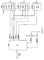
- Fig. 2 shows a hardware configuration which permits switching between alternative boot memories in an embodiment of the invention.
- The preferred embodiment is an 80486-based EISA-bus PC system. General features of the EISA bus are described by Glass, "Inside EISA," Byte magazine November 1989, pp/ 417ff, and in the EISA specification. General features of the Intel 80486 are described by Sartore, "The 80486: A Hardware Perspective," Byte Magazine IBM Special Edition, Fall 1989, pp. 67ff. Further detailed background on the 80486 may be found in the "80486 Programmer's Reference" and the "80486 Hardware Reference Manual," both available from Intel.
- Many of the architectural features of this system are conventional in modern PC systems. However, several unusual features are used. One of these is the provision for dual boot memories, with hardware and software switching betwen them. Another notable feature is the use of the "SLOB" controller chip described below.
- In the presently preferred embodiment, the system motherboard includes a custom chip, referred to herein as the "SLOB" chip, which performs a variety of special functions. These include reset control, X-bus transceiver control, and control of the boot memories and CMOS nonvoltaile memory.
- The "X-bus," or "extension bus," is an extension of the system bus, but is not directly connected to it. Instead, data is selectably transferred from the S-bus to the system bus, or vice versa, by bidirectional transceivers. The X-bus is commonly used, in PC architectures, to provide easier loading requirements for a variety of devices on the motherboard.
- The software core, in the presently preferred embodiment, resides in the protected 8k boot sector of a FLASH ROM or in the upper 8k of a 128k UVPROM. Selection of the primary ROM device is accomplished via a physical switch.
- Figure 2 shows more detail of how this is implemented. The SLOB chip supplies chip enable (CE) signals separately to the
FLASH EPROM 220 and to the UVEPROM 230 (and also to the NVRAM 240). An output enable line OE is connected to both boot ROMs, and address lines are also provided to both. A hardware switch provides a line ROMIN to the SLOB chip, to define which boot memory is the initial default target. - In the presently preferred embodiment, the FLASH EPROM has sector-by-sector protection. (This feature is found in the 28F001B type chip available from Intel).
- In the presently preferred embodiment, one
sector 220A, of only 8K bytes, is dedicated to the core software. This sector is protected by a hardware jumper, so corruption of the core software is unlikely. - To achieve automatic programming of the Flash memory from a plug-in ROM, the hardware must provide a switching mechanism that allows software to boot from one source and then toggle between sources. This switchability is also required to access EISA configuration from Flash if running BIOS out of a plug-in ROM.
- A user settable hardware switch determines which boot memory supplies the boot code at power-up or cold boot. This switch sets the polarity of a bit called ROMIN which is decoded by the hardware control logic to enable the selected boot source. This bit is readable from an I/O port, so that software can determine the source of the boot code, i.e. ROM(bit=0) or Flash (bit=1). The software then has the ability to toggle subsequently between accessing ROM or Flash by setting a bit that assumes the opposite state of ROMIN after a cold boot. This bit is called ROMEN and enables Flash when 0 and ROM when 1. This bit is readable as well as writable via an I/O port. This mechanism allows hardware to boot from ROM then gives software the ability to determine the presence of Flash memory and program Flash automatically by transferring the contents of the BIOS in ROM to the Flash.
- The chip referred to herein as the TRANE chip is a custom memory controller. Besides performing normal DRAM management functions, this chip also provides selection, by memory domains, of which memory areas will be cached or not.
- The actual implementation of the core software will now be described in detail by way of example only. It must be understood that this specific implementation is merely illustrative.
- Figure 1 is a flow chart which schematically shows key portions of the methods used in the computer system of the presently preferred embodiment.
- When the 80486 first comes out of reset, it comes up in real mode (but the high address bits are held high, so that the processor can go to the top of the 4-Gigabyte (32-bit) memory space. The processor accesses adddress FFFFFFFOh. See Glass, "Protected Mode", Byte Magazine December 1989, pp. 377ff.
- The actual implementation of key portions of the core software, in the presently preferred embodiment, will now be given. The following listings in documented assembly language also contain a large number of informal comments. These comments do not necessarily define the scope of the invention, but will help to explain the motivation, structure, and workings of the presently preferred embodiment.
- Some of the procedures actually used, in the presently preferred embodiment, will now be described in detail.
- Procedure 8kboot_strtis the power-on-reset entry point into the 8k boot sector code for a 128k FLASH EPROM. This code along with a reset vector is located in the upper 8k boot sector of a 128k FLASH EPROM. The reset vector will be located at 1fff0h (physical ROM address), and the start of this routine will be located at 1e000h (start.of the 8k boot sector). The reset vector will contain a NEAR jmp to this code, so execution will start in processor real mode, ROM native mode, at logical address 0ffffe000h. This procedure implements most of the steps in the flow chart of Figure 1. Specifically, this procedure:
- Saves the state of EAX and DX for later use by POST.
- Initializes a base address for the DRAM controller (the TRANE chip, in the presently preferred embodiment).
- Disable interrupts (NMI and INTR).
- If warm boot, jmp into POST SHUTDOWN routine.
- Else, if power-on check to see if we're running out of a UVPROM or the FLASH.
- If FLASH, jump to the "bootFLASH" procedure which programs the flash if the BIOS is corrupted or if the user has requested an upgrade.
- If UVPROM, jump to the "bootUVPROM" code which copies the UVPROM to the FLASH if a FLASH exists.
- If either "bootFLASH" or "bootUVPROM" does not program the flash, control returns to "do_reboot" which displays a SmartVu message and halts. NOTE: Because of the redundancy between this code and early parts of POST, (RESET, SHUTDOWN) the BIOS is NOT dependent on this code. This means that a working BIOS can be built for a 64k non-FLASH ROM architecture by simply removing this module from the build process. The original 64k BIOS reset/initialization logic has been left untouched.
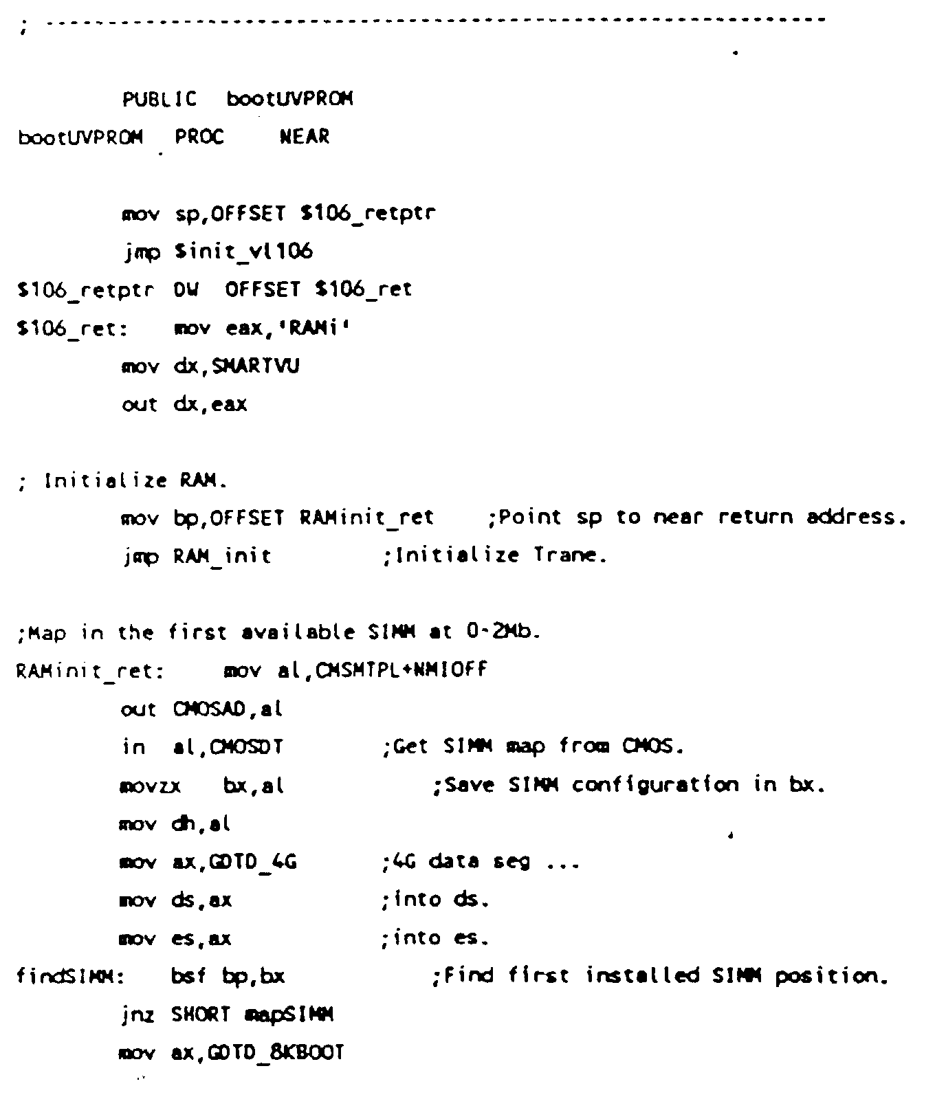
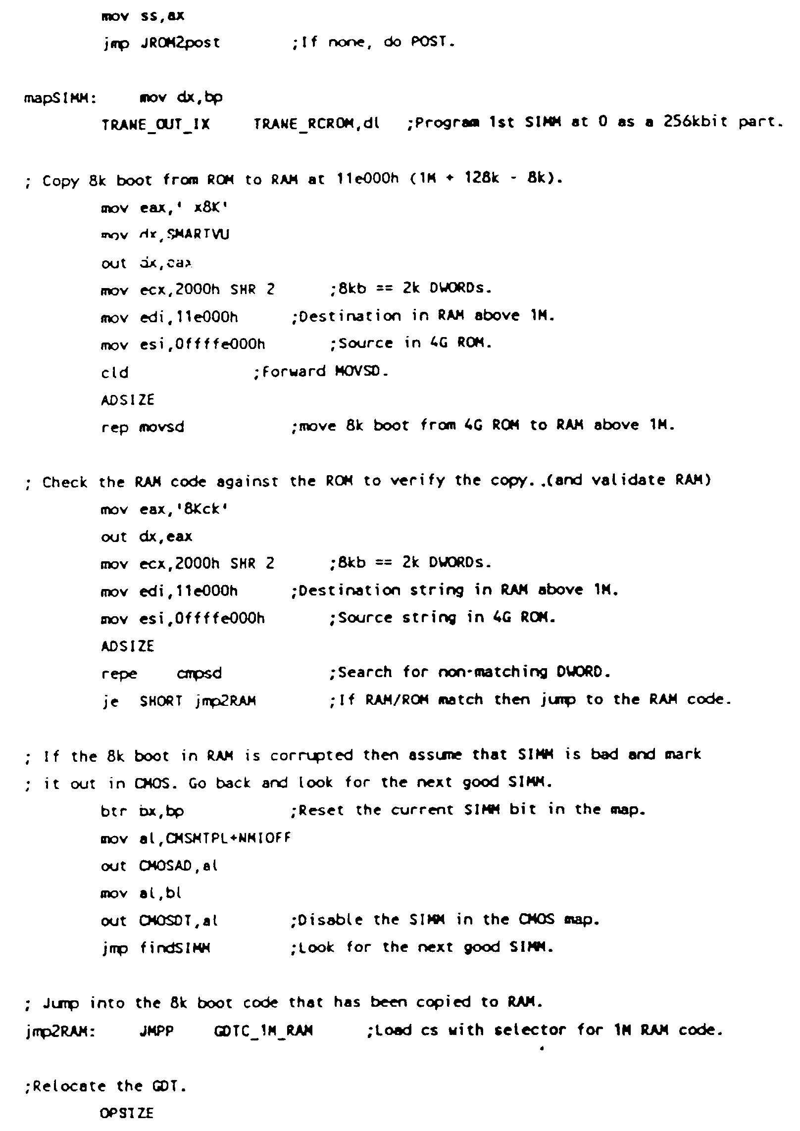
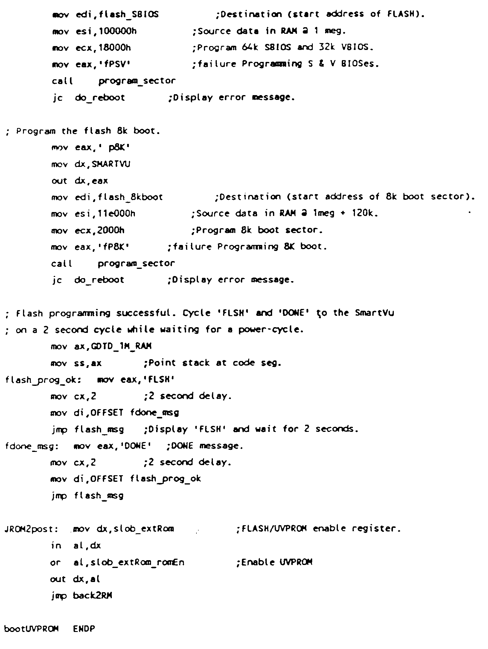
- Procedure bootUVPROMcontains the 8k power-on logic executed when a UVPROM is installed. When cold-booting from a UVPROM, this code is executed to look for a FLASH ROM and if present, attempts to copy the entire UVPROM contents into the FLASH. If FLASH programming is unsuccessful for any number of reasons, e.g., FLASH is not present, 8k boot sector is not jumpered for erase/programming, etc., then this routine just bails back into POST.


- Procedure bootFlash contains the 8K power-on logic executed when the system boots from the Flash.
- The steps are as follow:
- Checksum the system and video BIOS (96K).
- If checksum is good, go to I.
- If checksum is bad, go to II.
- I. - Does the user request a BIOS upgrade?
- If upgrade is selected, go to II.
- If upgrade is not selected, we are done with this routine and shall go to do regular POST.
- II. - Reset the upgrade option to prevent an endless loop.
- Initialize a lot of stuff.
- Initialize 106 so that we have SmartVu.
- Slob initialization.
- Trane initialization and get at least 2 meg of DRAM.
- Initialize the refresh counter.
- Set refresh page to 0 through the DMA controller.
- Copy code to RAM and execute from RAM.
- Set up stack.
- Test and initialize timers.
- Calibrate count before first call to DLY100.
- Set up the DMA controllers.
- Set up the interrupt descriptor table.
- Set up the interrupt controllers.
- Initialize the floppy subsystem.
- Copy the BIOS from floppy.
- If unsuccessful, display error message and halt.
- Make sure we indeed have a valid BIOS in RAM.
- Set the Flash up for programming.
- Copy the BIOS from RAM to Flash.
- If unsuccessful, display error message and halt.
- Initialize a lot of stuff.
- The actual assembly language realization used contains numerous other procedures, which will now be detailed. Most of these procedures are completely conventional. However, any of these procedures which have any particular relevance to the claimed inventions are actually listed below.
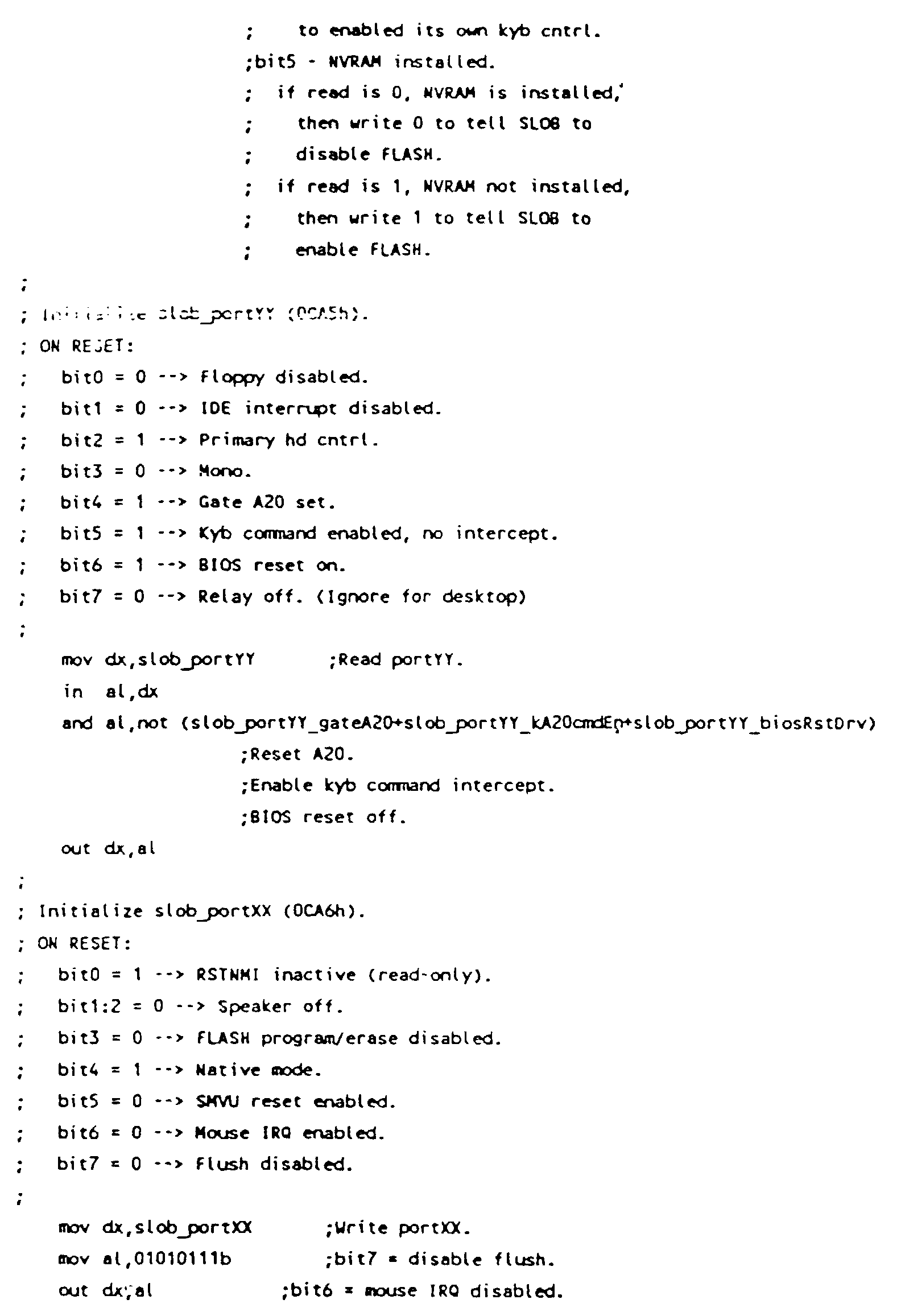
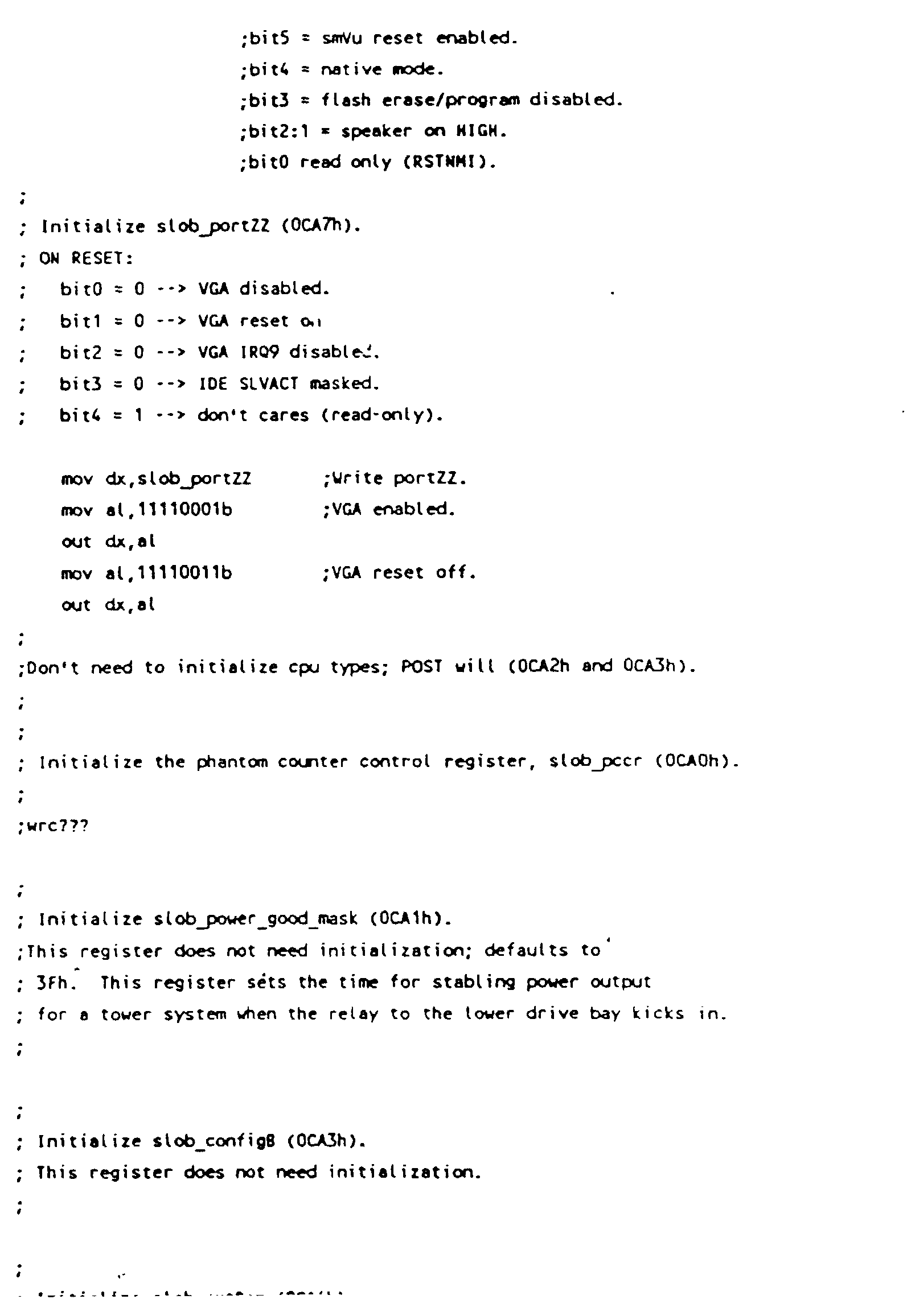
- This procedure initializes the "SLOB" and "TRANE" chips.



- Procedure RAM_initperforms RAM initialization for the 8k boot code, initializes TRANE, identifies memory, initializes it, turns on refresh and points RCR0 to a block from 0 - 2Mb.
Inputs:
HSM_xx ... Host state machine initialization tables.
FS ... Must point to a 4Gb data selector based @ 0.
bp contains the return address.
NOTE: It doesn't matter what type of SIMM we have identified. The presence test assumes that it's a 256kbit chip and initializes the RCR accordingly. If it's actually a 1Mbit or a 4Mbit SIMM it should still behave ok if it's programmed as a 256kbit. Since all we need is 128kb of RAM for copying the UVPROM, who cares what size the SIMM really is?
Outputs:
SUCCESS ... If successful, returns the following: - All SIMMs identified as present or not and
tabulated in CMSMTPL below.
CMSMTPL... CMOS byte containing the SIMM map. - RCROM points to 2 Mb of DRAM. SIMMs for this RAS programmed as 256kbit devices.
- Refresh enabled.
- Procedure $init_vl106 initializes the vL106. The VL106 is a chip which, among other functions, replaces the 8742 keyboard handler.)
- This procedure is a Protected mode entry routine.
Inputs:
DS ... points to the segment containing "gdt_ptr" and NULL_IDT. - This routine is created for the floppy code to run in real mode.
Inputs: none.
Outputs: real mode. - This routine is created for the floppy code. This will switch the execution back to protected after the floppy code is executed. [Uses different IDT and GDT tables ub low RAM.]
Inputs: none.
Outputs: protected mode. - This routine checksums the CMOS range 10h thru 2Dh.
Inputs:
DI ... contains NEAR return offset.
Outputs: none. - Procedure flash_msg displays the SMARTVU message in EAX, waits CX seconds and returns to the NEAR address in DI.
Inputs:
SS ... Writable segment pointing to code.
Dl ... Contains the NEAR return address.
CX ... The number of seconds to delay after displaying the SMARTVU message.
EAX ... Contains the SmartVu message. - Procedure delay waits for CX seconds. This procedure uses the RTC to implement a delay specified by the count in seconds in CX. If the RTC battery is bad, we just execute a fixed delay loop of DUMMY_DELAY iterations. Inputs:
cx ... Countains the number of seconds to delay. - This routine reads the seconds count from the RTC (real-time clock), and waits if a time update is in progress.
Inputs:
SI ... Contains the NEAR return address.
Outputs:
AL ... Contains the RTC seconds count. - This routine beeps!
Inputs:
cx = frequency.
di = near return address.
Outputs:
none. - This routine tests and initializes the timers.
- Procedure setupDMA will set up the DMA controllers just like the regular POST. The code are identical so as not to introduce any problem with the INT13H routine.
Inputs:
Native mode, protected mode.
Outputs:
If error, let regular POST reports the error.
If no error, DMA controllers are now ready for the INT13H routine. - Procedure setupPIC will set up the PICs just like the regular POST. The code is identical to that used in the POST, so as not to introduce any problem with the INT13H routine.
Inputs:
Native mode, protected mode.
Outputs:
The PICs are now ready for the INT13H routine. - Procedure copy copies the new BIOS from the floppy to RAM. The steps are as follow:
- Find out if file exists. The file has to be on a 1.2M floppy in the root directory with a filename of "DELLBIOS.BIN".
- Procedure fileExist reads in the root directory, and searches to see whether file "DELLBIOS.BIN" is in the directory.
Inputs:
none.
Outputs:
Carry clear if file exists.
ax has the first disk cluster if file exists.
bx:dx has file size. - Procedure setTypedetermines the type of floppy drive and sets the drive parameters accordingly.
Inputs:
none.
Outputs:
Parameters are initialized. - Procedure copyFile copies the desired file from drive 0 to RAM.
The steps are as follow: - Make sure the file size is what we expected.
- Read the FAT table.
- Copy the file to DRAM.
- Procedure sanityCheck will try to verify that the BIOS copied is a legitimate Dell BIOS.
Inputs:
BIOS (112K) spans from 5000:0000 thru 6000:C000.
Outputs:
Carry set if we do not have a legl BIOS.

- Procedure next gets the next link from a 12-bit FAT. Input:
ax = current entry number.
Output:
ax = next element in the chain. - Procedure rel2abs converts the relative sector number to the absolute sector location.
Input:
ax = relative sector number.
Output:
ch = track number.
cl = sector number.
dh = head number.
dl = 0 = drive number. - Procedure getFat reads in the FAT table.
Inputs:
es = GDTD_BUFFER.
Outputs:
Carry set if error.
If successful, FAT resides from 4000:0000 thru 4000:0E00. - Procedure program writes data into the flash ROM.
Inputs:
none.
Outputs:
Carry set if error.


- Procedure erase_sectorperforms the following steps:
- Clear the status register.
- Set the FLASH to read status mode.
- Set the FLASH for erase.
- Do the erase.
- Verify the erase is successful by reading the status register.
- Set the carry flag if erase unsuccessful.
- Clear the status register.
- Set the FLASH to read array mode.
- Procedure program_sectorwrites a sector of the flash ROM. Inputs:
ecx = number of bytes to program.
ds:esi points to beginning of data.
es:edi points to beginning of sector.
The steps are as follow: - Clear the status register.
- Set the FLASH to read status mode.
- Go and program the sector.
- Abort if error with the carry flag set.
- Clear the status register.
- Set the FLASH to read array mode.
- Procedure enable_fProgramenables program/erase operations on the FLASH ROM.
Inputs: none.
Outputs:
FLASH is ready to be programmed or erased.
- Procedure disable_fProgramdisables FLASH program/erase.
- Inputs:
- none.
- Outputs:
- FLASH cannot be programmed or erased.
- Procedure usecWait creates cx microseconds of delay.
Inputs:
cx = number of usec.
Outputs:
cx destroyed. - Procedure clr_Flash_status clears the FLASH status register. This routine was created because the new spec requires the address to be at 00000h of the Flash.
- Inputs:
- none.
- Outputs:
- Flash status register cleared.
- Procedure read_Flash_statusreads the FLASH status register at 00000h of the Flash.
- Inputs:
- none.
- Outputs:
- Flash status register read in al.
- Procedure NMI_ISR is a dummy interrupt handler, which swallows any NMMI interrupt.
- This routine tests the DMA address and word count registers.
Input:
CX = # of ports to test
DX = first port to test
SI = increment between ports
Output: flags ?
AL = ?
AH = ?
CX = 0 - Procedure CALB_SPD ("calibrate speed") sets DLLY_CNT with count for 100 us
- Procedure fdISR is the floppy drive controller interrupt handler. The steps are as follow:
- Send EOI to master PIC.
- Set interrupt bit in DRVSTAT to indicate an interrupt has occurred.
- Procedure int13h determines and executes the desired intl3h procedure functions.
- Procedure resetFlopresets the floppy system. This is part of the INT13H procedure.
Inputs:
ah = 0
dl = drive number (0-3), bit7 = 0 for floppy.
Outputs:
Carry flag set if error.
ah = status/error code.
ds:ERRSTAT(FDATA) = ah. - Procedure readSectorreads al sectors from the floppy.
Inputs:
ah = 02h.
al = number of sectors.
ch = track number.
cl = sector number.
dh = head number.
dl = drive number.
es:bx = address of buffer.
Outputs:
Carry flag set if error.
al = number of sectors transferred, ah = status = ERRSTAT. - Procedure setCarrysets the carry flag on the stack. This is part of the INT13H procedure.
- Procedure clrCarryclears the carry flag on the stack. This is part of the INT13H procedure.
- Inputs:
- none.
- Outputs:
- Carry flag in the flag register on the stack is cleared.
- Procedure dskResetresets the floppy system. This is part of the INT13H procedure.
- The steps are as follow:
- Disable interrupts.
- Clear DRVSTAT and ERRSTAT.
- Get floppy motor status.
- Issue reset command.
- Turn off reset command.
- Enable interrupts and wait for reset result interrupt.
- Check result.
- Procedure waitInt waits for a FDC interrupt. This is part of the INT13H procedure. This routine uses a regular wait instead of int15h.
- Inputs:
- none.
- Outputs:
- Carry flag set if timeout error, else not.
ERRSTAT bit7 = 1 if timeout. - Procedure fdcRdy waits for the floppy controller to be ready. This is part of the INT13H procedure.
- Inputs:
- none.
- Outputs:
- Carry flag set if timeout.
- Procedure sisStat senses the interrupt status. This is part of the INT13H procedure.
- Inputs:
- none.
- Outputs:
- Carry flag set if error, ERRSTAT set, ah = FDC status,
else Carry flag clear and al = present cylinder. - Procedures wrtCmd and wrtCmdA write commands to the FDC, and are part of the INT13H procedure.
Inputs:
al = command.
ds points to FDATA.
Outputs:
Carry flag and ERRSTAT set if error.
ah, dx destroyed. - Procedure rsltRd7 reads 7 result bytes from the FDC. Procedure rsltRd reads cx result bytes from the FDC. These are part of the INT13H procedure. Inputs:
cx = number of result bytes to read.
ds points to FDATA.
Outputs:
al = FDC status.
ah = FDC ST0, only valid if no carry.
ERRSTAT bit 7 = 1, carry set on timeout.
ERRSTAT bit 5 = 1, carry set if FDC results cannot be flushed.
Carry set if less results available than expected.
DSKST = FDC ST0, only valid if no carry.
dx non-zero. - Procedure i82077exist determines if a i82077 FDC is installed.
- This is part of the INT13H procedure.
- Inputs:
- none.
- Outputs:
- Carry flag set if i82077 installed and the FIFO enabled.
stk_tmp bit0=1 if i82077 installed and bit1 = 1 if FIFO enabled. - Procedure mltCmd2 writes 2 commands to the FDC. Procedure mltCmd writes cx commands to the FDC. These are part of the INT13H procedure.
Inputs:
cx = number of bytes to write (mltCmd).
bx = starting table offset.
Outputs:
es:si = disk parameter block.
ERRSTAT bit7 = 1 on timeout, bit5 = 1 on controller error.
Carry flag set on timeout or controller error, else not set. - Procedure dpbAdr puts the address of the disk parameter block into es:di. This is part of the INT13H procedure.
- Inputs:
- none.
- Outputs:
- es:si points to disk parameter block.
- Procedure configure issues the configure command to enable the FIFO in the i82077 FDC. This is part of the INT13H procedure.
Inputs:
ah = byte 2 of configure command.
Outputs:
Carry flag set if FDC error, else cleared. - Procedure dskMot turns the floppy drive motor on. This is part of the INT13H procedure.
Inputs:
dl = drive number. - Outputs:
- none.
- Procedure chkChg checks the change line on the floppy drive. This is part of the INT13H procedure.
- Inputs:
- none.
- Outputs:
- Carry flag set if error.
- Procedure getDrvInfogets drive information from HDCFLG. This is part of the INT13H procedure.
- Inputs:
- none.
- Outputs:
- Low 3 bits of al = drive information.
- Procedure clrChg tests and clear the change line. This is part of the INT13H procedure.
Inputs:
dl = drive number.
Outputs:
Carry flag set if timeout.
ERRSTAT = timeout or change line error. - Procedures doSeek and doSeek2 will seek to track specified by ch. This is part of the INT13H procedure.
Inputs:
ch = track to seek.
Outputs:
Carry flag and ERRSTAT set if error. - Procedure driHedSelloads the head (HDS) and the drive (DS1, DS0) parameters to the FDC. This is part of the INT13H procedure.
Inputs: none.
Outputs: none. - Procedure initDMA will initialize the DMA controller for floppy operations. This is part of the INT13H procedure.
- Inputs:
- none.
- Outputs:
- Carry flag and ERRSTAT set if error.
- Procedure headSettle conditionally waits for the head to settle. This is part of the INT13H procedure.
Inputs:
dx non-zero if head settle wait needed.
Outputs:
es:si points to DPB. - Procedure spinup conditionally waits for the floppy to spinup. This is part of the INT13H procedure.
- Procedure chkTypchecks the media type. This routine is called prior to read/write operation to verify and update, if necessary, FDMED. Returns with the carry flag set if no remaining valid FDMEDs to try. This is part of the INT13H procedure.
Inputs:
FDMED, ERRSTAT (if non-zero, it is a retry).
bx = drive.
Outputs:
FDMED updated:
ERRSTAT = carry flag = 0 if any more valid rate/step combos. FDMED restored:
FDOPER = 0.
ERRSTAT and carry flag set if no more valid rate/step combos.; - Procedure fdTypIfgets floppy disk type from CMOS if CMOS is valid. This is part of the INT13H procedure.
- Inputs:
- none.
- Outputs:
- Carry flag set if CMOS invalid, else
al = drive type, zero flag set if no drive or type unknown,
top of ah non-zero if another drive. - Procedure fdTypegets floppy disk type from CMOS. This is part of the FDTYPIF routine, and part of the INT13H procedure.
- Inputs:
- none.
- Outputs:
- al = drive type, zero flag set if no drive or type unknown,
top of ah non-zero if another drive. - Procedure setRate sets the transfer rate. This is part of the INT13H procedure.
Inputs:
bx = drive number.
Outputs:
Rate control port updated. - Procedure chkRes reads and checks the results from the FDC. This is part of the INT13H procedure.
- Inputs:
- none.
- Outputs:
- Carry flag set if error.
al = number of sectors transferred. - Procedure afterTrysets the zero flag if there is still more retry after an unsuccessful operation. This is part of the INT13H procedure.
- Inputs:
- none.
- Outputs:
- Zero flag set if there is still more retry.
- Procedure resTyp forces FDMED[bx] media known and restores compatible low bits. This is part of the INT13H procedure.
Inputs:
ah = top three bits of FDMED[bx].
Outputs:
FDMED[bx] bit4 = 1. - Procedure stoDrvInfo puts the drive information in al into HDCFLG. This is part of the INT13H procedure.
Inputs:
al = drive information.
bx = drive number.
Outputs:
Drive information in [bx] half of HDCFLG. - Procedure initFD will initialize the floppy subsystem and all the variables used by the INT13H routine. This is part of the INT13H routine.
- Inputs:
- none.
- Outputs:
- DRVSTAT, FMOTS, FDTIMO, ERRSTAT, DSKST, HDCFLG, FDMED, FDOPER, WTACTF, FDRATE, are all initialized.
- Procedure dskTest will test and determine drive type.
Inputs:
ss:bp points to stack frame for disk driver.
stk_dl[bp] = drive number.
Outputs:
FDMED[drive #], HDCFLG initialized.
Carry flag set if no drive. - Procedure sDrvSt senses the drive status.
- Inputs:
- none.
- Outputs:
- Carry flag set, ERRSTAT set if error.
Carry flag clear, ah=FDC's ST0 if no error.
Zero flag set if track 0 reached. - Procedure ckFdCfg checks the floppy configuration data against the actual installed hardware.
Inputs:
byte ptr stk_dl[bp] = drive number.
si points to the media type for that drive number.
Outputs:
Carry set if different configuration. - Procedure CMREADis a Subroutine to Read a CMOS register. Input:
AL = CMOS register address to read
Output:
AL = CMOS register value
Interrupt Flag cleared
Carry Flag cleared
Zero Flag cleared. - This is a Subroutine to Write a CMOS register.
Input:
AH = CMOS register address to write, Bit 7 = 0 enables NMI
AL = Value to write to CMOS register
Output:
Interrupt Flag cleared
Carry Flag cleared
Zero Flag cleared. - This procedure will delay for 100 us. The loop count for the delay function is taken from DLY_CNT. DLY_CNT is set during ATPOST, and whenever turbo speed is changed by the routine CALB_SPD. It takes no inputs and gives no outputs.
- It will be recognized by those skilled in the art that the innovative concepts disclosed in the present application can be applied in a wide variety of contexts.
- In particular, the disclosed innovations are not by any means limited to DOS systems, nor to systems using 80x86 microprocessors, nor to systems using a single microprocessor as the CPU. The disclosed innovations provide generally applicable architectural techniques, which can be applied to a wide variety of computer systems, including high-performance systems and multiprocessing systems.
- It should also be noted that the source for the user-supplied BIOS code does not have to be a floppy drive. For example, a tape cartridge or a dial-in telephone interface could be used instead.
- In addition, although the Flash EPROM is the preferred device technology for the second nonvolatile boot memory, it should be recognized that other nonvolatile storage technologies can be used if they become practical. Thus, many of the innovative features of the presently preferred embodiment can be directly adapted to a system using EEPROMs, battery-backed SRAM chips, ferroelectric RAMs, or future technologies.
- It should also be noted that BOTH of the boot memories can be rewriteable nonvolatile memories if desired. Even though this arrangement provides slightly less robustness than the preferred embodiment, it still provides a large added margin of safety over the use of a single rewriteable nonvolatile boot memory.
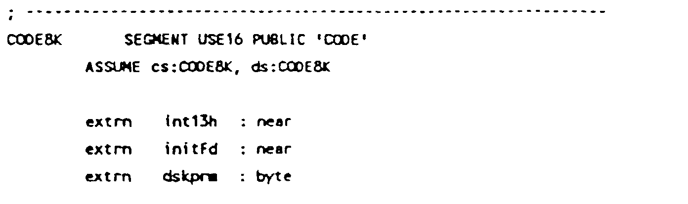

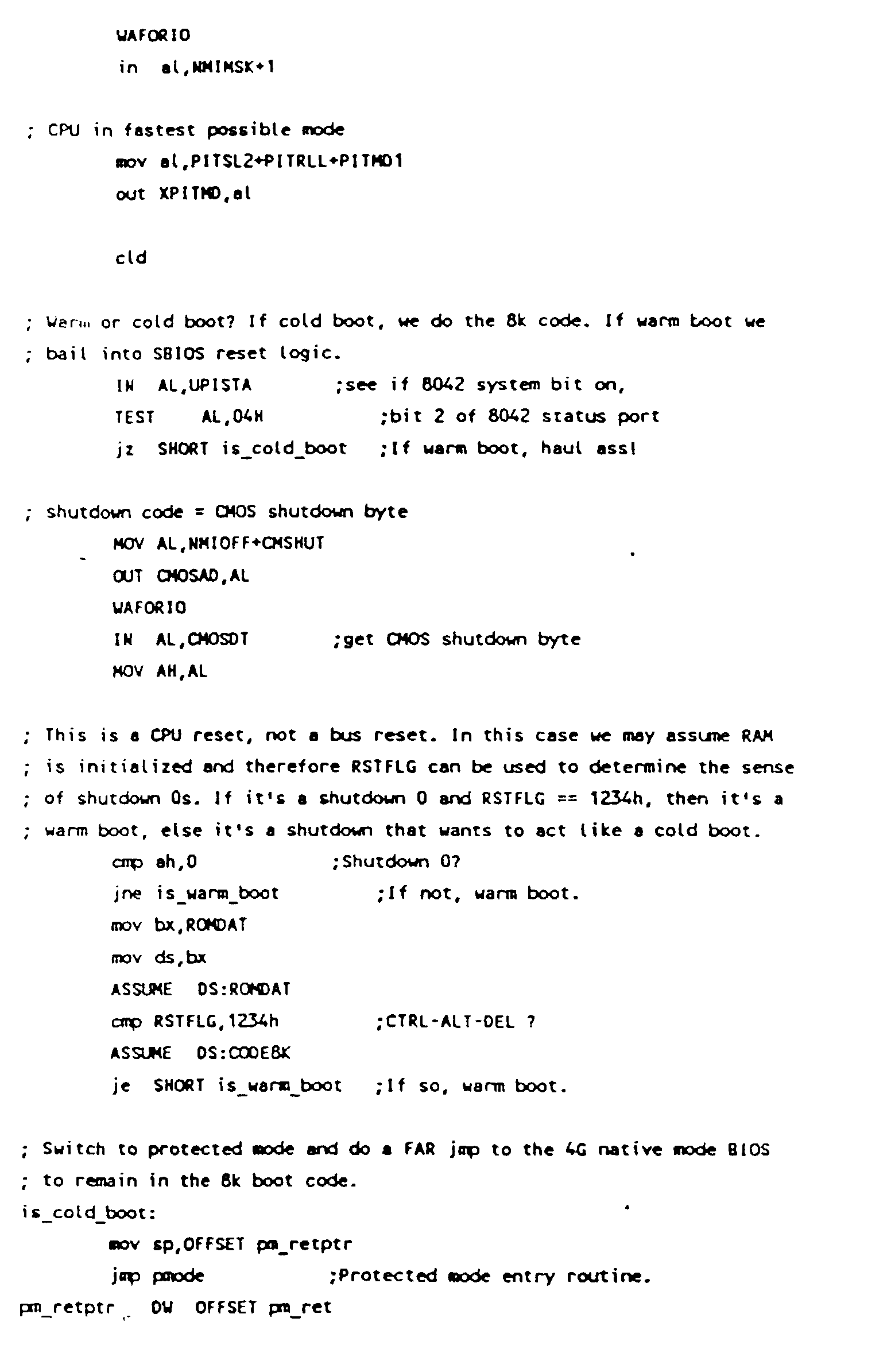
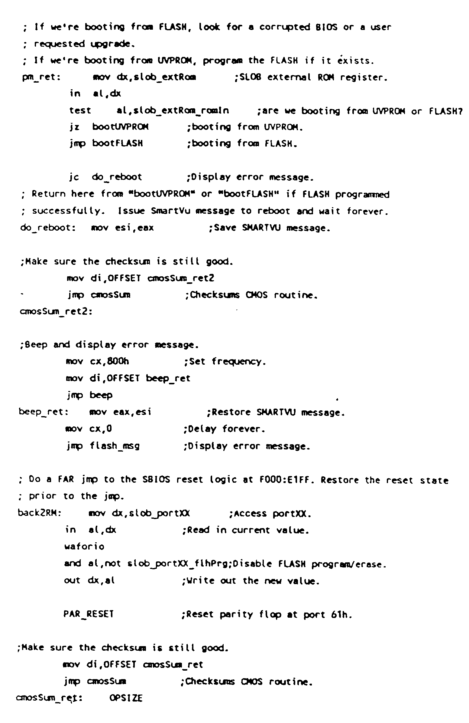

Native-mode, protected-mode, Trane has grabbed its I/O address.
Outputs:
Either halts or go to do regular POST.
If the BIOS checksum is good and no upgrade is requested,
this routine will jump to do regular POST.
If the BIOS checksum is bad or an upgrad is requested, then this routine will halt at the end.
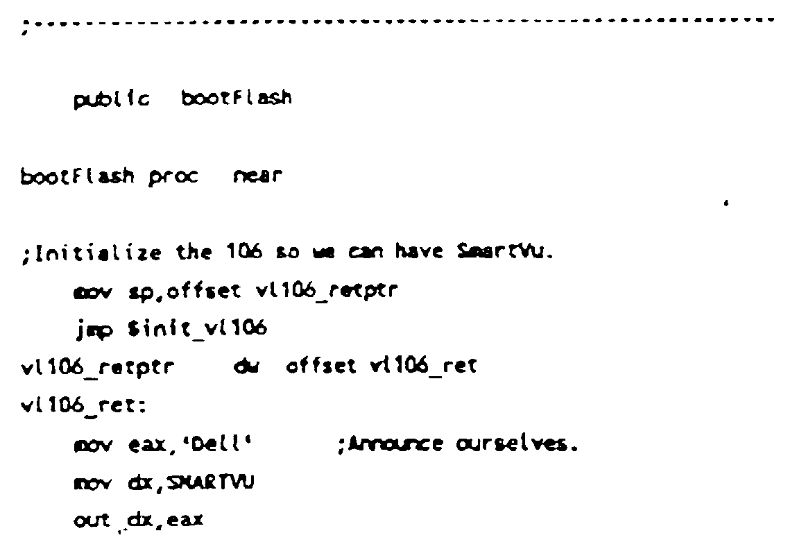


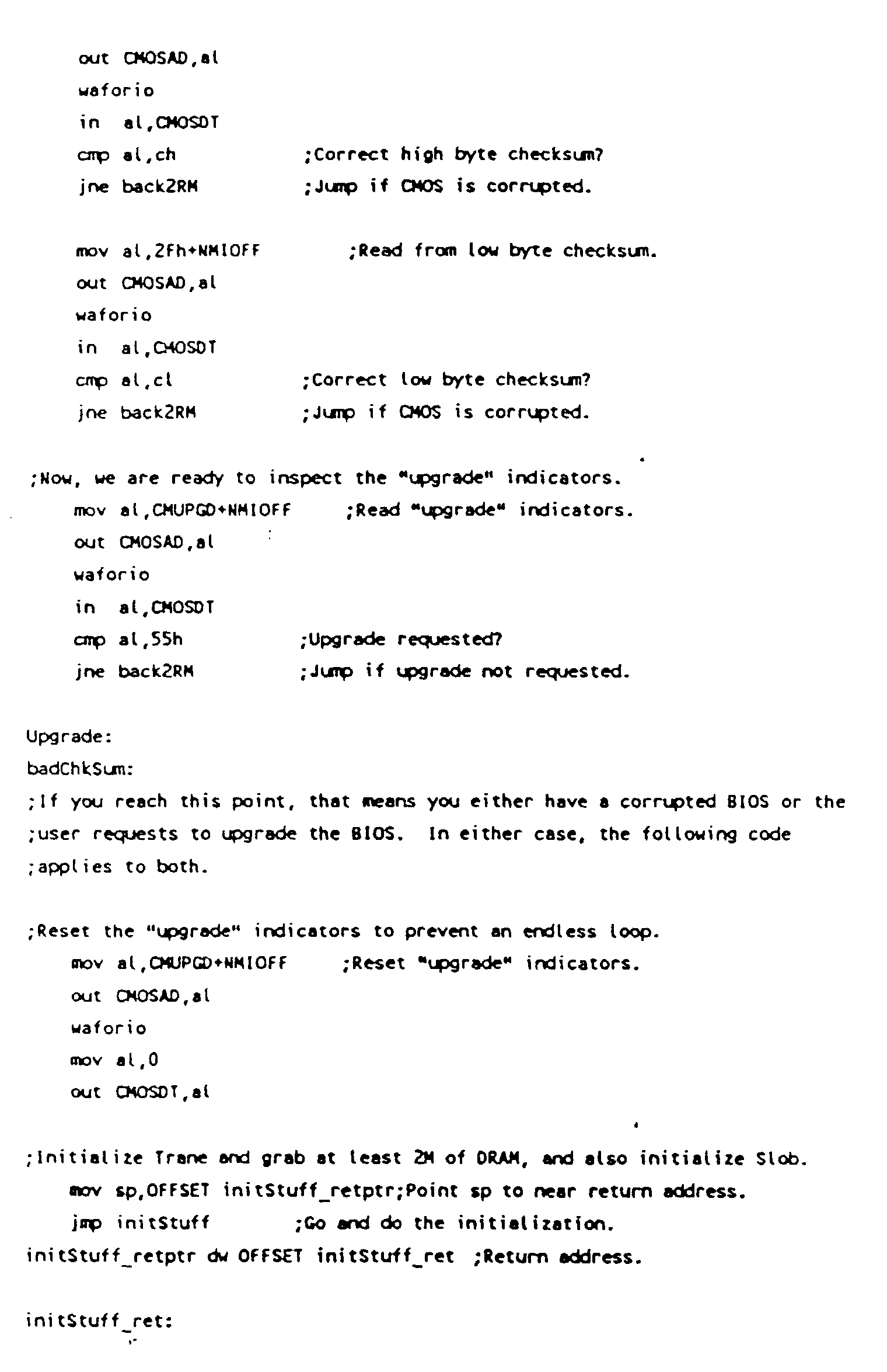


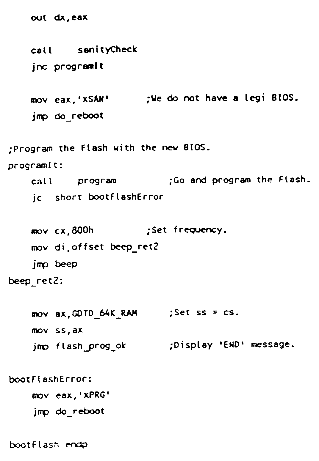
none.
Outputs:
Carry flag set if error.


ax has the first disk cluster of the file.
bx:dx has file size.
es=GDTD_BUFFER.
Outputs:
Carry flag set if error.
es:edi = address of sector to be erased.
FLASH program/erase better be enabled before calling this routine.
Outputs:
If successful, carry flag cleared.
;
; WARNING!!! - the FLASH program jumper must be set for program/erase.
;

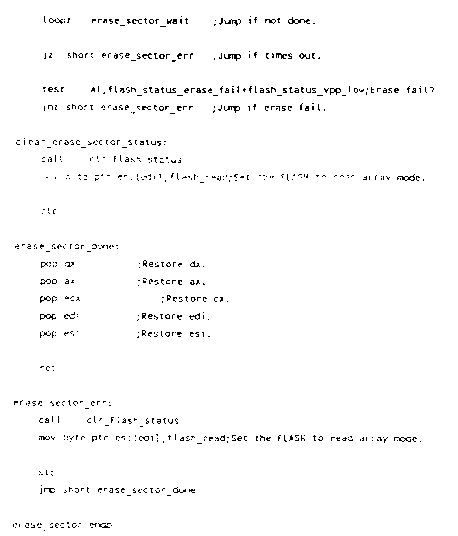
If successful, carry flag cleared.
;
: WARNING!!! -- The FLASH program jumper must be set for program/erase.
;

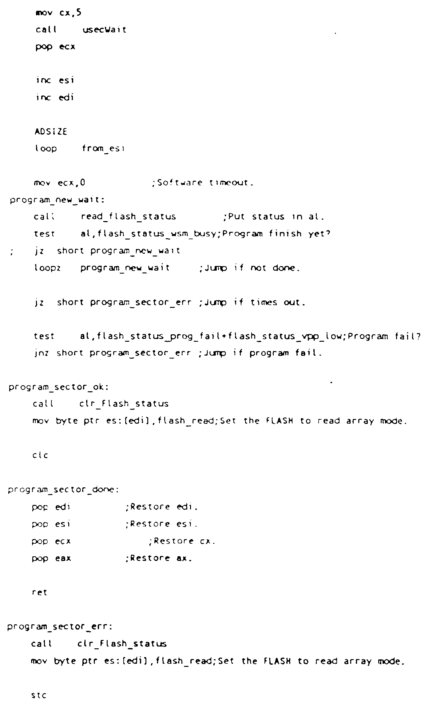


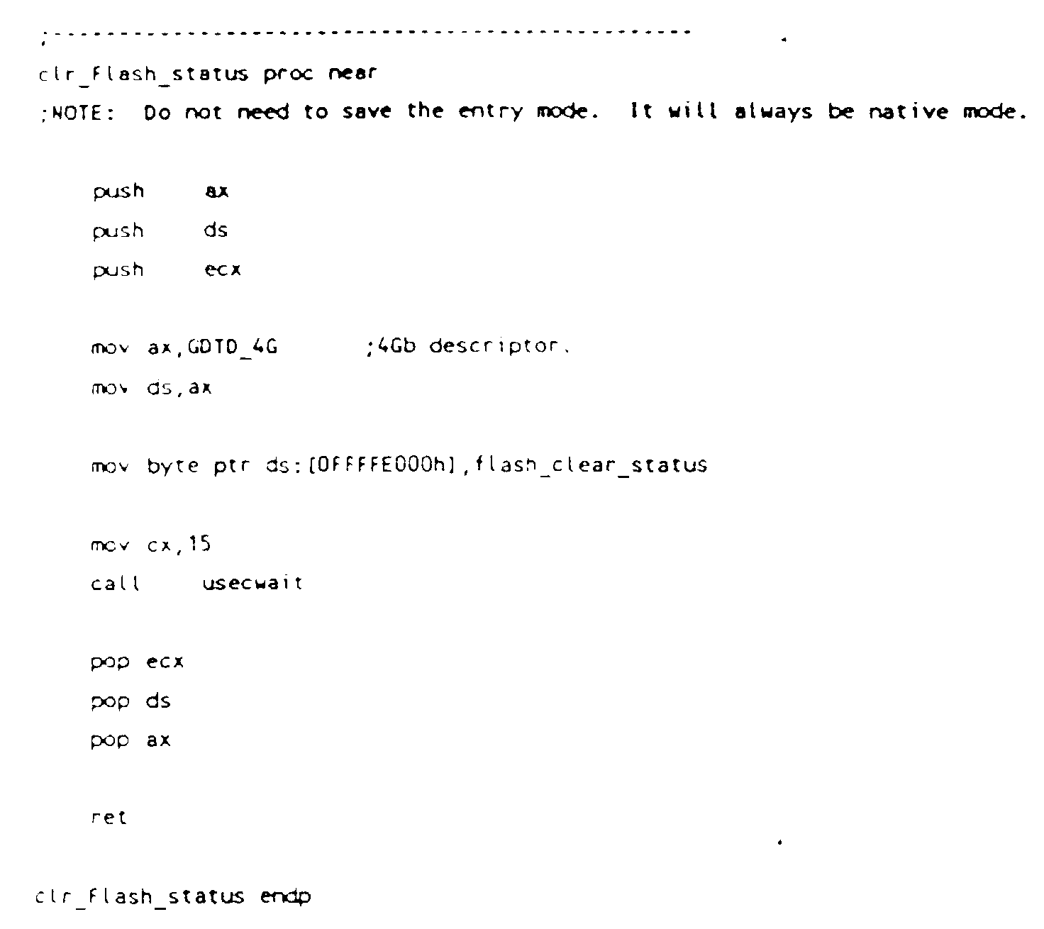

dl = drive number (0-3), bit7 = 0 for floppy.
Outputs:
Carry flag set if error.
ds:ERRSTAT(FDATA) = ah = error code if error, else 0.
Claims (5)
- A computer system including:characterised in thatan electrically rewritable first non-volatile memory (220, 220A) for holding bootstrapping instructions required by the computer system after a hard reset of the system,a second non-volatile memory (230) which holds bootstrapping instructions required by the computer system after a hard reset of the system anda controller (210) through which the electrically rewritable first non-volatile memory is connectable to the computer system,the electrically rewritable first non-volatile memory includes a first sector (220A), which can be protected against overwriting, for holding core bootstrapping instructions and a second sector (220) for holding further instructions,the second non-volatile memory is connectable through the controller (210) to the computer system and the computer system further includes:setting means capable of being set either to prevent or to permit the overwriting of the first sector (220A) of the electrically rewritable first non-volatile memory anduser-operable selection means connected to the controller (210) for selecting either the electrically rewritable first non-volatile memory or the second non-volatile memory as the source of bootstrapping instructions for the computer system following a hard reset of the computer system,the bootstrapping instructions held in the second non-volatile memory being effective to copy bootstrapping instructions from the second non-volatile memory to the first and second sectors (220A,220) of the electrically rewritable first non-volatile memory when the user-operable selection means is set to select the second non-volatile memory as the source of bootstrapping instructions and the setting means is set to permit the overwriting of the first sector (220A) of the electrically rewritable first non-volatile memory andthe core bootstrapping instructions supplied to the first sector (220A) of the electrically rewritable first non-volatile memory being effective, in response to a user-entry requesting upgrade in the computer system, to perform the overwriting of instructions held in the second sector (220) of the electrically rewritable first non-volatile memory from an external source.
- A computer system as claimed in claim 1, including a multi-element diagnostic display for indicating the result of an operation to overwrite instructions held in the electrically rewritable first non-volatile memory.
- A computer system as claimed in claim 1 or claim 2, wherein the second non-volatile memory is an ultraviolet-erasable programmable read-only-memory (UVPROM).
- A method of operating a computer system including an electrically rewritable first non-volatile memory (220, 220A) for holding bootstrapping instructions required by the computer system after a hard reset of the system, a second non-volatile memory (230) which holds bootstrapping instructions required by the computer system after a hard reset of the system and a controller (210) through which the electrically rewritable first non-volatile memory is connectable to the computer system,
characterised by the steps of:providing in the computer system setting means capable of being set either to prevent or to permit the over writing of the first sector (220A) of the electrically rewritable first non-volatile memory and user-operable selection means connected to the controller (210) for selecting either the electrically rewritable first non-volatile memory or the second non-volatile memory as the source of bootstrapping instructions for the computer system following a hard reset of the computer system, wherein the second non-volatile memory is connectable through the controller (210) to the computer system,selecting the second non-volatile memory as the source of bootstrapping instructions when the user-operable selection means is set to select the second non-volatile memory as the source of bootstrapping instructions,copying core bootstrapping instructions from the second non-volatile memory into a first sector (220A) of the electrically rewritable first non-volatile memory and copying other start-up instructions from the second non-volatile memory into a second sector (220) of the electrically rewritable first non-volatile memory when the setting means is set to permit the overwriting of the first sector (220A) of the electrically rewritable first non-volatile memory,providing protection against the overwriting of the core bootstrapping instructions copied into the first sector (220A) of the electrically rewritable first non-volatile memory,selecting the electrically rewritable first non-volatile memory as the source of bootstrapping instructions for the computer system andusing the core bootstrapping instructions to effect the overwriting of the bootstrapping instructions copied into the second sector (220) of the electrically rewritable first non-volatile memory by externally supplied bootstrapping instructions in response to a user entry requesting upgrade in the computer system. - A method as claimed in claim 4, including the steps of reading bootstrapping instructions from the electrically rewritable first non-volatile memory, subjecting the read-out bootstrapping instructions to validity checks and, when a validity check is failed, overwriting the bootstrapping instructions held in the electrically rewritable first non-volatile memory by the bootstrapping instructions held in the second non-volatile memory.
Applications Claiming Priority (2)
| Application Number | Priority Date | Filing Date | Title |
|---|---|---|---|
| US707121 | 1985-02-28 | ||
| US07/707,121 US5388267A (en) | 1991-05-29 | 1991-05-29 | Method and apparatus for updating and restoring system BIOS functions while maintaining BIOS integrity |
Publications (3)
| Publication Number | Publication Date |
|---|---|
| EP0524719A2 EP0524719A2 (en) | 1993-01-27 |
| EP0524719A3 EP0524719A3 (en) | 1993-09-08 |
| EP0524719B1 true EP0524719B1 (en) | 1999-08-11 |
Family
ID=24840435
Family Applications (1)
| Application Number | Title | Priority Date | Filing Date |
|---|---|---|---|
| EP92304936A Expired - Lifetime EP0524719B1 (en) | 1991-05-29 | 1992-05-29 | Computer system with alterable bootstrapping software and method therefor |
Country Status (5)
| Country | Link |
|---|---|
| US (1) | US5388267A (en) |
| EP (1) | EP0524719B1 (en) |
| JP (1) | JPH06175829A (en) |
| KR (1) | KR100239585B1 (en) |
| DE (1) | DE69229765T2 (en) |
Families Citing this family (189)
| Publication number | Priority date | Publication date | Assignee | Title |
|---|---|---|---|---|
| US5872967A (en) * | 1989-12-29 | 1999-02-16 | Packard Bell Nec | Method for warm boot from reset |
| US5822601A (en) * | 1989-12-29 | 1998-10-13 | Packard Bell Nec | Apparatus to allow a CPU to control the relocation of code blocks for other CPUs |
| US6009495A (en) * | 1989-12-29 | 1999-12-28 | Packard Bell Nec | Protected address range in an electrically erasable programmable read only memory |
| IT1254937B (en) * | 1991-05-06 | 1995-10-11 | DYNAMIC UPDATE OF NON-VOLATILE MEMORY IN A COMPUTER SYSTEM | |
| US5826075A (en) * | 1991-10-16 | 1998-10-20 | International Business Machines Corporation | Automated programmable fireware store for a personal computer system |
| US6131159A (en) * | 1992-05-08 | 2000-10-10 | Paradyne Corporation | System for downloading programs |
| US5634079A (en) * | 1992-05-15 | 1997-05-27 | Zenith Data Systems Corporation | System for providing for a parallel port with standard signals and a flash recovery mode with second predetermined signals redefining parallel port with alternate functions |
| US6182187B1 (en) * | 1993-04-07 | 2001-01-30 | Compaq Computer Corporation | System ROM including a flash EPROM and a ROM for storing primary boot code replacing a block flash EPROM |
| US5522076A (en) * | 1993-05-13 | 1996-05-28 | Kabushiki Kaisha Toshiba | Computer system having BIOS (basic input/output system)-ROM (Read Only Memory) writing function |
| US5600801A (en) * | 1993-07-15 | 1997-02-04 | Dell Usa, L.P. | Multiple function interface device for option card |
| DE9313005U1 (en) * | 1993-08-30 | 1995-01-05 | Siemens AG, 80333 München | Electronic assembly with at least one decentralized processor device of a multi-processor controlled system |
| JP3310060B2 (en) | 1993-09-13 | 2002-07-29 | 株式会社東芝 | Storage device and control program rewriting method for the same |
| US5752063A (en) * | 1993-12-08 | 1998-05-12 | Packard Bell Nec | Write inhibited registers |
| US5764995A (en) * | 1994-03-25 | 1998-06-09 | Packard Bell Nec | Write once read only registers |
| US6148441A (en) * | 1994-04-06 | 2000-11-14 | Dell Usa, L.P. | Method for reprogramming flash ROM in a personal computer implementing an EISA bus system |
| GB2290890B (en) * | 1994-06-29 | 1999-03-24 | Mitsubishi Electric Corp | Information processing system |
| US5864698A (en) * | 1994-08-24 | 1999-01-26 | Packard Bell Nec | Disk based bios |
| US5694583A (en) * | 1994-09-27 | 1997-12-02 | International Business Machines Corporation | BIOS emulation parameter preservation across computer bootstrapping |
| US5652868A (en) * | 1994-09-27 | 1997-07-29 | International Business Machines Corporation | Data processor having BIOS decryption of emulated media images |
| US5797023A (en) * | 1994-10-17 | 1998-08-18 | Digital Equipment Corporation | Method and apparatus for fault tolerant BIOS addressing |
| US5581768A (en) * | 1995-02-27 | 1996-12-03 | Intel Corporation | Method and apparatus for executing applications in place from write once/seldom memories |
| KR0172001B1 (en) * | 1995-12-05 | 1999-03-30 | 윤종용 | Re-programming apparatus of bios memory |
| US5748940A (en) * | 1995-08-17 | 1998-05-05 | Compaq Computer Corporation | Secure updating of non-volatile memory |
| US5822581A (en) * | 1995-09-29 | 1998-10-13 | Intel Corporation | Method for CMOS configuration information storage and retrieval in flash |
| GB9603582D0 (en) | 1996-02-20 | 1996-04-17 | Hewlett Packard Co | Method of accessing service resource items that are for use in a telecommunications system |
| US5682528A (en) * | 1995-12-22 | 1997-10-28 | Tandem Computers Incorporated | Spoon-feed initialization in a multiprocessor system |
| EP0790554A1 (en) * | 1996-02-16 | 1997-08-20 | Siemens Aktiengesellschaft | Method and circuit to control a firmware loading process |
| US5701492A (en) * | 1996-03-29 | 1997-12-23 | Canon Kabushiki Kaisha | Fail-safe flashing of EPROM |
| KR100568642B1 (en) | 1996-04-11 | 2006-04-07 | 가부시끼가이샤 히다치 세이사꾸쇼 | ATAPI disk drive device |
| KR100198382B1 (en) * | 1996-05-07 | 1999-06-15 | 윤종용 | Computer with multi-booting function |
| EP0825530A3 (en) * | 1996-06-20 | 2004-06-02 | Sharp Kabushiki Kaisha | Computer apparatus having electrically rewritable nonvolatile memory, and nonvolatile semiconductor memory |
| JP2940480B2 (en) * | 1996-07-05 | 1999-08-25 | 日本電気株式会社 | Computer system |
| JPH1027035A (en) * | 1996-07-12 | 1998-01-27 | Fujitsu Ltd | Information processing device |
| US5819087A (en) * | 1996-07-19 | 1998-10-06 | Compaq Computer Corporation | Flash ROM sharing between processor and microcontroller during booting and handling warm-booting events |
| US5805882A (en) * | 1996-07-19 | 1998-09-08 | Compaq Computer Corporation | Computer system and method for replacing obsolete or corrupt boot code contained within reprogrammable memory with new boot code supplied from an external source through a data port |
| US5930504A (en) * | 1996-07-22 | 1999-07-27 | Intel Corporation | Dynamic nonvolatile memory update in a computer system |
| US5793943A (en) * | 1996-07-29 | 1998-08-11 | Micron Electronics, Inc. | System for a primary BIOS ROM recovery in a dual BIOS ROM computer system |
| US20010056532A1 (en) * | 1996-08-16 | 2001-12-27 | Barnes Cooper | Method and apparatus for fault tolerant flash upgrading |
| US5938764A (en) | 1996-10-23 | 1999-08-17 | Micron Electronics, Inc. | Apparatus for improved storage of computer system configuration information |
| US6151657A (en) * | 1996-10-28 | 2000-11-21 | Macronix International Co., Ltd. | Processor with embedded in-circuit programming structures |
| US6282675B1 (en) | 1997-08-06 | 2001-08-28 | Macronix International Co., Ltd. | Fault-tolerant architecture for in-circuit programming |
| US6842820B2 (en) | 1997-10-03 | 2005-01-11 | Macronix International Co., Ltd. | Processor with embedded in-circuit programming structures |
| US6493788B1 (en) | 1996-10-28 | 2002-12-10 | Macronix International Co., Ltd. | Processor with embedded in-circuit programming structures |
| US5974250A (en) * | 1996-12-13 | 1999-10-26 | Compaq Computer Corp. | System and method for secure information transmission over a network |
| US5901285A (en) * | 1996-12-18 | 1999-05-04 | Intel Corporation | Hierarchical erasure key protection for computer system data |
| US6122733A (en) * | 1997-01-02 | 2000-09-19 | Intel Corporation | Method and apparatus for updating a basic input/output system |
| US6047373A (en) | 1997-01-02 | 2000-04-04 | Intel Corporation | Method and apparatus for setting the operating parameters of a computer system |
| KR100298420B1 (en) * | 1997-03-10 | 2001-10-24 | 윤종용 | Method for updating rom bios |
| US6748524B1 (en) | 1997-04-30 | 2004-06-08 | Gateway, Inc. | Display and recordation of non-volatile memory changes |
| KR100258966B1 (en) | 1997-05-02 | 2000-06-15 | 윤종용 | BIOS upgrade method using serial communication |
| US6134673A (en) * | 1997-05-13 | 2000-10-17 | Micron Electronics, Inc. | Method for clustering software applications |
| US6163849A (en) * | 1997-05-13 | 2000-12-19 | Micron Electronics, Inc. | Method of powering up or powering down a server to a maintenance state |
| US6182180B1 (en) | 1997-05-13 | 2001-01-30 | Micron Electronics, Inc. | Apparatus for interfacing buses |
| US6499073B1 (en) | 1997-05-13 | 2002-12-24 | Micron Electronics, Inc. | System using programmable processor for selectively enabling or disabling power to adapter in response to respective request signals |
| US6253334B1 (en) | 1997-05-13 | 2001-06-26 | Micron Electronics, Inc. | Three bus server architecture with a legacy PCI bus and mirrored I/O PCI buses |
| US6247079B1 (en) * | 1997-05-13 | 2001-06-12 | Micron Electronics, Inc | Apparatus for computer implemented hot-swap and hot-add |
| US6122746A (en) * | 1997-05-13 | 2000-09-19 | Micron Electronics, Inc. | System for powering up and powering down a server |
| US6249828B1 (en) | 1997-05-13 | 2001-06-19 | Micron Electronics, Inc. | Method for the hot swap of a mass storage adapter on a system including a statically loaded adapter driver |
| US6202160B1 (en) | 1997-05-13 | 2001-03-13 | Micron Electronics, Inc. | System for independent powering of a computer system |
| US6195717B1 (en) | 1997-05-13 | 2001-02-27 | Micron Electronics, Inc. | Method of expanding bus loading capacity |
| US6330690B1 (en) | 1997-05-13 | 2001-12-11 | Micron Electronics, Inc. | Method of resetting a server |
| US6148355A (en) * | 1997-05-13 | 2000-11-14 | Micron Electronics, Inc. | Configuration management method for hot adding and hot replacing devices |
| US6243773B1 (en) | 1997-05-13 | 2001-06-05 | Micron Electronics, Inc. | Configuration management system for hot adding and hot replacing devices |
| US6324608B1 (en) * | 1997-05-13 | 2001-11-27 | Micron Electronics | Method for hot swapping of network components |
| US6170067B1 (en) | 1997-05-13 | 2001-01-02 | Micron Technology, Inc. | System for automatically reporting a system failure in a server |
| US5987554A (en) * | 1997-05-13 | 1999-11-16 | Micron Electronics, Inc. | Method of controlling the transfer of information across an interface between two buses |
| US6073255A (en) * | 1997-05-13 | 2000-06-06 | Micron Electronics, Inc. | Method of reading system log |
| US6134668A (en) * | 1997-05-13 | 2000-10-17 | Micron Electronics, Inc. | Method of selective independent powering of portion of computer system through remote interface from remote interface power supply |
| US6363497B1 (en) | 1997-05-13 | 2002-03-26 | Micron Technology, Inc. | System for clustering software applications |
| US6243838B1 (en) | 1997-05-13 | 2001-06-05 | Micron Electronics, Inc. | Method for automatically reporting a system failure in a server |
| US6219734B1 (en) | 1997-05-13 | 2001-04-17 | Micron Electronics, Inc. | Method for the hot add of a mass storage adapter on a system including a statically loaded adapter driver |
| US6249834B1 (en) | 1997-05-13 | 2001-06-19 | Micron Technology, Inc. | System for expanding PCI bus loading capacity |
| US6179486B1 (en) | 1997-05-13 | 2001-01-30 | Micron Electronics, Inc. | Method for hot add of a mass storage adapter on a system including a dynamically loaded adapter driver |
| US6163853A (en) | 1997-05-13 | 2000-12-19 | Micron Electronics, Inc. | Method for communicating a software-generated pulse waveform between two servers in a network |
| US6145098A (en) | 1997-05-13 | 2000-11-07 | Micron Electronics, Inc. | System for displaying system status |
| US6122758A (en) * | 1997-05-13 | 2000-09-19 | Micron Electronics, Inc. | System for mapping environmental resources to memory for program access |
| US6192434B1 (en) | 1997-05-13 | 2001-02-20 | Micron Electronics, Inc | System for hot swapping a programmable adapter by using a programmable processor to selectively disabling and enabling power thereto upon receiving respective control signals |
| US6247080B1 (en) | 1997-05-13 | 2001-06-12 | Micron Electronics, Inc. | Method for the hot add of devices |
| US5892928A (en) * | 1997-05-13 | 1999-04-06 | Micron Electronics, Inc. | Method for the hot add of a network adapter on a system including a dynamically loaded adapter driver |
| US6418492B1 (en) | 1997-05-13 | 2002-07-09 | Micron Electronics | Method for computer implemented hot-swap and hot-add |
| US6173346B1 (en) | 1997-05-13 | 2001-01-09 | Micron Electronics, Inc. | Method for hot swapping a programmable storage adapter using a programmable processor for selectively enabling or disabling power to adapter slot in response to respective request signals |
| US6269412B1 (en) | 1997-05-13 | 2001-07-31 | Micron Technology, Inc. | Apparatus for recording information system events |
| US6138250A (en) * | 1997-05-13 | 2000-10-24 | Micron Electronics, Inc. | System for reading system log |
| US6170028B1 (en) | 1997-05-13 | 2001-01-02 | Micron Electronics, Inc. | Method for hot swapping a programmable network adapter by using a programmable processor to selectively disabling and enabling power thereto upon receiving respective control signals |
| US6269417B1 (en) | 1997-05-13 | 2001-07-31 | Micron Technology, Inc. | Method for determining and displaying the physical slot number of an expansion bus device |
| US6266721B1 (en) | 1997-05-13 | 2001-07-24 | Micron Electronics, Inc. | System architecture for remote access and control of environmental management |
| US6338150B1 (en) * | 1997-05-13 | 2002-01-08 | Micron Technology, Inc. | Diagnostic and managing distributed processor system |
| US6292905B1 (en) | 1997-05-13 | 2001-09-18 | Micron Technology, Inc. | Method for providing a fault tolerant network using distributed server processes to remap clustered network resources to other servers during server failure |
| US6304929B1 (en) | 1997-05-13 | 2001-10-16 | Micron Electronics, Inc. | Method for hot swapping a programmable adapter by using a programmable processor to selectively disabling and enabling power thereto upon receiving respective control signals |
| US6202111B1 (en) | 1997-05-13 | 2001-03-13 | Micron Electronics, Inc. | Method for the hot add of a network adapter on a system including a statically loaded adapter driver |
| US5987536A (en) * | 1997-05-22 | 1999-11-16 | International Business Machines Corporation | Computer system having flash memory bios which can be accessed while protected mode operating system is running |
| WO1998054642A1 (en) * | 1997-05-30 | 1998-12-03 | Koninklijke Philips Electronics N.V. | Failsafe method for upgrading set-top system software from a network server |
| GB9713094D0 (en) * | 1997-06-21 | 1997-08-27 | Philips Electronics Nv | Optical disc drive |
| EP1008042A4 (en) * | 1997-08-06 | 2004-04-14 | Macronix Int Co Ltd | Fault-tolerant architecture for in-circuit programming |
| US6038689A (en) * | 1997-08-21 | 2000-03-14 | Digital Equipment Corporation | Fault notification system and process using local area network |
| US6009524A (en) * | 1997-08-29 | 1999-12-28 | Compact Computer Corp | Method for the secure remote flashing of a BIOS memory |
| KR19990026189A (en) * | 1997-09-23 | 1999-04-15 | 윤종용 | How to update BIOS ROM |
| US5913058A (en) * | 1997-09-30 | 1999-06-15 | Compaq Computer Corp. | System and method for using a real mode bios interface to read physical disk sectors after the operating system has loaded and before the operating system device drivers have loaded |
| US6199173B1 (en) | 1997-10-01 | 2001-03-06 | Micron Electronics, Inc. | Method for mapping environmental resources to memory for program access |
| US6009541A (en) * | 1997-10-01 | 1999-12-28 | Micron Electronics, Inc. | Apparatus for performing an extensive diagnostic test in conjunction with a bios test routine |
| US6035420A (en) * | 1997-10-01 | 2000-03-07 | Micron Electronics, Inc. | Method of performing an extensive diagnostic test in conjunction with a bios test routine |
| US6154835A (en) * | 1997-10-01 | 2000-11-28 | Micron Electronics, Inc. | Method for automatically configuring and formatting a computer system and installing software |
| US6138179A (en) * | 1997-10-01 | 2000-10-24 | Micron Electronics, Inc. | System for automatically partitioning and formatting a primary hard disk for installing software in which selection of extended partition size is not related to size of hard disk |
| US6065053A (en) * | 1997-10-01 | 2000-05-16 | Micron Electronics, Inc. | System for resetting a server |
| US6212585B1 (en) | 1997-10-01 | 2001-04-03 | Micron Electronics, Inc. | Method of automatically configuring a server after hot add of a device |
| US6175490B1 (en) | 1997-10-01 | 2001-01-16 | Micron Electronics, Inc. | Fault tolerant computer system |
| US6088816A (en) * | 1997-10-01 | 2000-07-11 | Micron Electronics, Inc. | Method of displaying system status |
| US6263387B1 (en) | 1997-10-01 | 2001-07-17 | Micron Electronics, Inc. | System for automatically configuring a server after hot add of a device |
| US6438687B2 (en) | 1997-10-30 | 2002-08-20 | Micron Technology, Inc. | Method and apparatus for improved storage of computer system configuration information |
| US5987605A (en) * | 1998-02-28 | 1999-11-16 | Hewlett-Packard Co. | Methods and apparatus for dual-boot memory selection, update, and recovery in a programmable device |
| US20020069316A1 (en) * | 1998-04-15 | 2002-06-06 | Mattison Phillip E. | Method and apparatus for protecting flash memory |
| US6298443B1 (en) | 1998-04-24 | 2001-10-02 | Dell Usa, L.P. | Method and system for supplying a custom software image to a computer system |
| US6363492B1 (en) | 1998-04-30 | 2002-03-26 | Compaq Computer Corporation | Computer method and apparatus to force boot block recovery |
| US6240519B1 (en) | 1998-04-30 | 2001-05-29 | Compaq Computer Corporation | Computer method and apparatus to prompt for administrative password to flash a corrupted non-volatile memory |
| US6223234B1 (en) | 1998-07-17 | 2001-04-24 | Micron Electronics, Inc. | Apparatus for the hot swap and add of input/output platforms and devices |
| US6205503B1 (en) | 1998-07-17 | 2001-03-20 | Mallikarjunan Mahalingam | Method for the hot swap and add of input/output platforms and devices |
| JP3727485B2 (en) | 1999-04-02 | 2005-12-14 | シャープ株式会社 | Microcomputer with built-in nonvolatile memory |
| IL129947A (en) * | 1999-05-13 | 2003-06-24 | Tadiran Telecom Business Syste | Method and apparatus for downloading software into an embedded system |
| EP1063589A1 (en) * | 1999-06-25 | 2000-12-27 | TELEFONAKTIEBOLAGET L M ERICSSON (publ) | Device for processing data and corresponding method |
| US6473856B1 (en) * | 1999-06-30 | 2002-10-29 | International Business Machines Corporation | Gold code backup for corrupt boot code recovery |
| US6715074B1 (en) * | 1999-07-27 | 2004-03-30 | Hewlett-Packard Development Company, L.P. | Virus resistant and hardware independent method of flashing system bios |
| US6434697B1 (en) | 1999-10-06 | 2002-08-13 | Micron Technology, Inc. | Apparatus for savings system configuration information to shorten computer system initialization time |
| US6519698B1 (en) | 1999-10-06 | 2003-02-11 | Micron Technology, Inc. | Method for saving system configuration information to shorten computer system initialization time by checking the state of a chassis intrusion detection circuit |
| US6513114B1 (en) | 1999-12-08 | 2003-01-28 | Dell Products L.P. | System and methods for providing selectable initialization sequences |
| US6560703B1 (en) | 2000-04-18 | 2003-05-06 | International Business Machines Corporation | Redundant updatable self-booting firmware |
| US6732267B1 (en) | 2000-09-11 | 2004-05-04 | Dell Products L.P. | System and method for performing remote BIOS updates |
| US6804773B1 (en) | 2000-10-03 | 2004-10-12 | Dell Products L.P. | System and method for transferring information over a network |
| US6414513B1 (en) | 2000-10-03 | 2002-07-02 | International Business Machines Corporation | Customized system-readable hardware/firmware integrated circuit version information |
| US6757838B1 (en) | 2000-10-13 | 2004-06-29 | Hewlett-Packard Development Company, L.P. | Hardware independent implementation of computer system BIOS recovery |
| US6834331B1 (en) | 2000-10-24 | 2004-12-21 | Starfish Software, Inc. | System and method for improving flash memory data integrity |
| US6715106B1 (en) | 2000-11-10 | 2004-03-30 | Dell Products L.P. | Bios corruption detection system and method |
| FR2819070B1 (en) * | 2000-12-28 | 2003-03-21 | St Microelectronics Sa | PROTECTION METHOD AND DEVICE AGAINST HACKING INTEGRATED CIRCUITS |
| US6842855B2 (en) | 2001-01-26 | 2005-01-11 | Dell Products L.P. | System and method for providing information to a computer system |
| US6751569B2 (en) | 2001-01-26 | 2004-06-15 | Dell Products L.P. | System and method for receiving information from a test apparatus |
| CZ300977B6 (en) * | 2001-02-26 | 2009-09-30 | Iss Europe, Spol. S R.O. | Controller with PCI and SCSI buses and computing system fitted with electronic semiconductor disk |
| US7065347B1 (en) | 2001-06-27 | 2006-06-20 | Peoplenet Communications Corporation | System and method for over the air programming |
| US6862681B2 (en) | 2001-07-16 | 2005-03-01 | International Business Machines Corporation | Method and system for master boot record recovery |
| JP4840553B2 (en) | 2001-07-31 | 2011-12-21 | 日本電気株式会社 | Wireless communication apparatus, boot program rewriting method and program |
| US20030028799A1 (en) * | 2001-07-31 | 2003-02-06 | Cordella Robert H. | Processes and systems for secure access to information resources using computer hardware |
| JP4434539B2 (en) * | 2001-12-26 | 2010-03-17 | 富士通マイクロエレクトロニクス株式会社 | Processor and boot method thereof |
| US7032106B2 (en) * | 2001-12-27 | 2006-04-18 | Computer Network Technology Corporation | Method and apparatus for booting a microprocessor |
| US7664903B2 (en) * | 2002-02-25 | 2010-02-16 | Solid Access Technologies LLC | Control unit with PCI and SCSI buses and computing system with electronic semiconductor disk |
| US7409435B1 (en) * | 2002-02-28 | 2008-08-05 | Sprint Communications Company L.P. | Integrated services hub binary file trial run process |
| US7080245B2 (en) * | 2002-05-23 | 2006-07-18 | Hewlett-Packard Development Company, L.P. | Method and system of switching between two or more images of firmware on a host device |
| SG118149A1 (en) * | 2002-08-02 | 2006-01-27 | Kie James Chan Loke | Program for upgrading operating systems in non-volatile memory |
| KR100532413B1 (en) * | 2002-12-02 | 2005-12-02 | 삼성전자주식회사 | apparatus and method for protecting flash memory |
| US7337309B2 (en) * | 2003-03-24 | 2008-02-26 | Intel Corporation | Secure online BIOS update schemes |
| US7246222B2 (en) | 2003-04-21 | 2007-07-17 | Hewlett-Packard Development Company, L.P. | Processor type determination based on reset vector characteristics |
| US7322029B2 (en) * | 2003-05-08 | 2008-01-22 | American Megatrends, Inc. | Method and system for recovering program code in a computer system |
| US20040243998A1 (en) * | 2003-05-27 | 2004-12-02 | Dell Products L.P. | Method and apparatus for restoring an information handling system to a previous software state |
| JP3906825B2 (en) * | 2003-06-17 | 2007-04-18 | 日本電気株式会社 | Computer system, computer system activation method and program |
| US7487345B2 (en) * | 2003-10-10 | 2009-02-03 | Dell Products L.P. | Method of comparing build capability flags of replacement BIOS with boot capability flags of current BIOS to determine compatibility between BIOS revisions and installed hardware during flash update |
| US7397624B2 (en) | 2003-11-06 | 2008-07-08 | Seagate Technology Llc | Transducers for ferroelectric storage medium |
| US8924522B2 (en) | 2003-12-23 | 2014-12-30 | Intel Corporation | Method and apparatus for remote modification of system configuration setting |
| US8990366B2 (en) | 2003-12-23 | 2015-03-24 | Intel Corporation | Method and apparatus for remote modification of system configuration |
| US7373498B2 (en) * | 2003-12-23 | 2008-05-13 | Intel Corporation | Method and apparatus for updating a system configuration through an active or passive update |
| US7234075B2 (en) * | 2003-12-30 | 2007-06-19 | Dell Products L.P. | Distributed failover aware storage area network backup of application data in an active-N high availability cluster |
| JP4544901B2 (en) * | 2004-04-19 | 2010-09-15 | 株式会社日立製作所 | Storage control system and boot control system |
| US7822937B2 (en) * | 2004-05-03 | 2010-10-26 | Gateway, Inc. | Method and apparatus for modifying reserve area of disk drive or memory |
| KR100604877B1 (en) | 2004-07-03 | 2006-07-31 | 삼성전자주식회사 | Apparatus and method for controlling the mapping of memory addresses in embedded systems |
| FR2872603B1 (en) | 2004-07-03 | 2007-02-09 | Samsung Electronics Co Ltd | METHOD AND DEVICE FOR EXECUTING THE INTEGRATED SYSTEM INITIATION CODE |
| JP2006099215A (en) * | 2004-09-28 | 2006-04-13 | Toshiba Tec Corp | Computer device with download board |
| US20060236084A1 (en) * | 2005-04-15 | 2006-10-19 | Dune-Ren Wu | Method and system for providing an auxiliary bios code in an auxiliary bios memory utilizing time expiry control |
| DE102005018910A1 (en) * | 2005-04-22 | 2006-10-26 | Endress + Hauser Gmbh + Co. Kg | A method of upgrading a microprocessor controlled device with new software code over a communication network |
| TW200825705A (en) * | 2006-04-26 | 2008-06-16 | Nxp Bv | Method and system for power-state transition controllers |
| US9047452B2 (en) * | 2006-07-06 | 2015-06-02 | Dell Products L.P. | Multi-user BIOS authentication |
| US7634799B2 (en) | 2006-07-10 | 2009-12-15 | Dell Products L.P. | Method for updating system BIOS after service event in order to support re-enablement of an O.C.U.R. device |
| DE102006043636A1 (en) * | 2006-09-18 | 2008-03-27 | Fujitsu Siemens Computers Gmbh | Computer system and method for updating program code |
| US7509544B2 (en) * | 2007-02-26 | 2009-03-24 | Inventec Corporation | Data repair and synchronization method of dual flash read only memory |
| US7953987B2 (en) * | 2007-03-06 | 2011-05-31 | International Business Machines Corporation | Protection of secure electronic modules against attacks |
| US7805598B2 (en) * | 2007-05-03 | 2010-09-28 | Dell Products L.P. | Auto-detecting and auto-correcting system state changes before booting into operating systems |
| US9098448B2 (en) * | 2007-05-29 | 2015-08-04 | Dell Products L.P. | Intelligent boot services |
| US8943491B2 (en) * | 2008-06-26 | 2015-01-27 | Lenovo Enterprise Solutions (Singapore) Pte. Ltd. | Systems and methods for maintaining CRTM code |
| TW201030518A (en) * | 2009-02-11 | 2010-08-16 | Inventec Corp | BIOS, computer device and BIOS recovery |
| US8238538B2 (en) | 2009-05-28 | 2012-08-07 | Comcast Cable Communications, Llc | Stateful home phone service |
| US20130117006A1 (en) * | 2011-11-07 | 2013-05-09 | Microsoft Corporation | Simulated boot process to detect introduction of unauthorized information |
| US9466377B2 (en) * | 2014-02-26 | 2016-10-11 | Infineon Technologies Ag | Method and device for processing an erase counter |
| US9424134B2 (en) * | 2014-03-28 | 2016-08-23 | Intel Corporation | Boot management in a non-volatile memory system |
| US9983885B2 (en) * | 2015-05-06 | 2018-05-29 | Elbit Systems Of America, Llc | BIOS system with non-volatile data memory |
| TWI553490B (en) * | 2015-07-29 | 2016-10-11 | 廣達電腦股份有限公司 | Method and system for remote system configuration management and non-transitory computer-readable storage medium |
| US9742568B2 (en) | 2015-09-23 | 2017-08-22 | Dell Products, L.P. | Trusted support processor authentication of host BIOS/UEFI |
| US20180275731A1 (en) * | 2017-03-21 | 2018-09-27 | Hewlett Packard Enterprise Development Lp | Processor reset vectors |
| US10997296B2 (en) * | 2017-03-22 | 2021-05-04 | Oracle International Corporation | System and method for restoration of a trusted system firmware state |
| US10802916B2 (en) * | 2017-08-04 | 2020-10-13 | Dell Products, L.P. | System and method to enable rapid recovery of an operating system image of an information handling system after a malicious attack |
| CN108763099B (en) * | 2018-04-18 | 2020-05-08 | 华为技术有限公司 | System startup method, device, electronic device and storage medium |
| JP7263101B2 (en) * | 2019-04-26 | 2023-04-24 | キヤノン株式会社 | Information processing device, data verification method |
| KR102941074B1 (en) | 2019-08-26 | 2026-03-19 | 에스케이하이닉스 주식회사 | Apparatus and method for handling firmware error in operation of memory system |
| CN113608769B (en) * | 2021-08-16 | 2024-05-03 | 广东亿云智控技术有限公司 | Method for parallel processing and self-upgrading based on multiple single-chip microcomputer |
| CN119782250B (en) * | 2024-11-22 | 2025-10-03 | 北京遥测技术研究所 | A software multi-source autonomous loading method based on SPAC-V8 embedded processor |
Family Cites Families (8)
| Publication number | Priority date | Publication date | Assignee | Title |
|---|---|---|---|---|
| US4430704A (en) * | 1980-01-21 | 1984-02-07 | The United States Of America As Represented By The Secretary Of The Navy | Programmable bootstrap loading system |
| US4663707A (en) * | 1984-05-25 | 1987-05-05 | Scientific Micro Systems, Inc. | Multilevel bootstrap apparatus |
| US5136713A (en) * | 1989-08-25 | 1992-08-04 | International Business Machines Corporation | Apparatus and method for decreasing the memory requirements for bios in a personal computer system |
| US5022077A (en) * | 1989-08-25 | 1991-06-04 | International Business Machines Corp. | Apparatus and method for preventing unauthorized access to BIOS in a personal computer system |
| US5210875A (en) * | 1989-08-25 | 1993-05-11 | International Business Machines Corporation | Initial bios load for a personal computer system |
| EP0500973B1 (en) * | 1991-02-25 | 1999-05-06 | Siemens Aktiengesellschaft | EEPROM and method for altering a bootstrap routine in the EEPROM |
| IT1254937B (en) * | 1991-05-06 | 1995-10-11 | DYNAMIC UPDATE OF NON-VOLATILE MEMORY IN A COMPUTER SYSTEM | |
| US5473775A (en) * | 1991-10-11 | 1995-12-05 | Kabushiki Kaisha Toshiba | Personal computer using flash memory as BIOS-ROM |
-
1991
- 1991-05-29 US US07/707,121 patent/US5388267A/en not_active Expired - Fee Related
-
1992
- 1992-05-19 KR KR1019920008421A patent/KR100239585B1/en not_active Expired - Lifetime
- 1992-05-28 JP JP4137001A patent/JPH06175829A/en active Pending
- 1992-05-29 EP EP92304936A patent/EP0524719B1/en not_active Expired - Lifetime
- 1992-05-29 DE DE69229765T patent/DE69229765T2/en not_active Expired - Lifetime
Also Published As
| Publication number | Publication date |
|---|---|
| KR100239585B1 (en) | 2000-01-15 |
| KR920022093A (en) | 1992-12-19 |
| DE69229765T2 (en) | 2000-03-02 |
| US5388267A (en) | 1995-02-07 |
| EP0524719A3 (en) | 1993-09-08 |
| EP0524719A2 (en) | 1993-01-27 |
| JPH06175829A (en) | 1994-06-24 |
| DE69229765D1 (en) | 1999-09-16 |
Similar Documents
| Publication | Publication Date | Title |
|---|---|---|
| KR100239585B1 (en) | How to operate a computer system with recoverable basic firmware | |
| US7165137B2 (en) | System and method for booting from a non-volatile application and file storage device | |
| US6148441A (en) | Method for reprogramming flash ROM in a personal computer implementing an EISA bus system | |
| US8185728B2 (en) | System boot using NAND flash memory and method thereof | |
| US6308265B1 (en) | Protection of boot block code while allowing write accesses to the boot block | |
| US5371876A (en) | Computer system with a paged non-volatile memory | |
| US5878256A (en) | Method and apparatus for providing updated firmware in a data processing system | |
| JP3195988B2 (en) | Nonvolatile semiconductor memory and computer system using the same | |
| US7908466B2 (en) | Method and apparatus for booting a microprocessor system using boot code stored on a serial flash memory array having a random-access interface | |
| US5937423A (en) | Register interface for flash EEPROM memory arrays | |
| US9063848B2 (en) | NAND flash memory system architecture | |
| KR100974561B1 (en) | Boot from Nonlinear Memory | |
| CN1330324A (en) | Data processing unit and method for controlling overwrited by non-volatility storage device | |
| US20080256352A1 (en) | Methods and systems of booting of an intelligent non-volatile memory microcontroller from various sources | |
| JP2971267B2 (en) | Personal computer using flash memory as BIOS-ROM | |
| KR100284260B1 (en) | Diskless boot device on PC | |
| Dipert et al. | Designing an updatable BIOS using flash memory |
Legal Events
| Date | Code | Title | Description |
|---|---|---|---|
| PUAI | Public reference made under article 153(3) epc to a published international application that has entered the european phase |
Free format text: ORIGINAL CODE: 0009012 |
|
| AK | Designated contracting states |
Kind code of ref document: A2 Designated state(s): DE FR GB IT |
|
| PUAL | Search report despatched |
Free format text: ORIGINAL CODE: 0009013 |
|
| RHK1 | Main classification (correction) |
Ipc: G06F 9/445 |
|
| AK | Designated contracting states |
Kind code of ref document: A3 Designated state(s): DE FR GB IT |
|
| 17P | Request for examination filed |
Effective date: 19940215 |
|
| 17Q | First examination report despatched |
Effective date: 19970317 |
|
| GRAG | Despatch of communication of intention to grant |
Free format text: ORIGINAL CODE: EPIDOS AGRA |
|
| GRAG | Despatch of communication of intention to grant |
Free format text: ORIGINAL CODE: EPIDOS AGRA |
|
| GRAH | Despatch of communication of intention to grant a patent |
Free format text: ORIGINAL CODE: EPIDOS IGRA |
|
| GRAH | Despatch of communication of intention to grant a patent |
Free format text: ORIGINAL CODE: EPIDOS IGRA |
|
| GRAA | (expected) grant |
Free format text: ORIGINAL CODE: 0009210 |
|
| AK | Designated contracting states |
Kind code of ref document: B1 Designated state(s): DE FR GB IT |
|
| REF | Corresponds to: |
Ref document number: 69229765 Country of ref document: DE Date of ref document: 19990916 |
|
| ITF | It: translation for a ep patent filed | ||
| ET | Fr: translation filed | ||
| PLBE | No opposition filed within time limit |
Free format text: ORIGINAL CODE: 0009261 |
|
| STAA | Information on the status of an ep patent application or granted ep patent |
Free format text: STATUS: NO OPPOSITION FILED WITHIN TIME LIMIT |
|
| 26N | No opposition filed | ||
| REG | Reference to a national code |
Ref country code: GB Ref legal event code: IF02 |
|
| PGFP | Annual fee paid to national office [announced via postgrant information from national office to epo] |
Ref country code: FR Payment date: 20110607 Year of fee payment: 20 |
|
| PGFP | Annual fee paid to national office [announced via postgrant information from national office to epo] |
Ref country code: GB Payment date: 20110525 Year of fee payment: 20 |
|
| PGFP | Annual fee paid to national office [announced via postgrant information from national office to epo] |
Ref country code: IT Payment date: 20110525 Year of fee payment: 20 Ref country code: DE Payment date: 20110527 Year of fee payment: 20 |
|
| REG | Reference to a national code |
Ref country code: DE Ref legal event code: R071 Ref document number: 69229765 Country of ref document: DE |
|
| REG | Reference to a national code |
Ref country code: DE Ref legal event code: R071 Ref document number: 69229765 Country of ref document: DE |
|
| REG | Reference to a national code |
Ref country code: GB Ref legal event code: PE20 Expiry date: 20120528 |
|
| PG25 | Lapsed in a contracting state [announced via postgrant information from national office to epo] |
Ref country code: DE Free format text: LAPSE BECAUSE OF EXPIRATION OF PROTECTION Effective date: 20120530 |
|
| PG25 | Lapsed in a contracting state [announced via postgrant information from national office to epo] |
Ref country code: GB Free format text: LAPSE BECAUSE OF EXPIRATION OF PROTECTION Effective date: 20120528 |