EP0524302B1 - Method and devices for decoring castings - Google Patents
Method and devices for decoring castings Download PDFInfo
- Publication number
- EP0524302B1 EP0524302B1 EP92906406A EP92906406A EP0524302B1 EP 0524302 B1 EP0524302 B1 EP 0524302B1 EP 92906406 A EP92906406 A EP 92906406A EP 92906406 A EP92906406 A EP 92906406A EP 0524302 B1 EP0524302 B1 EP 0524302B1
- Authority
- EP
- European Patent Office
- Prior art keywords
- alternative
- balancing
- plate
- movement
- clamping plate
- Prior art date
- Legal status (The legal status is an assumption and is not a legal conclusion. Google has not performed a legal analysis and makes no representation as to the accuracy of the status listed.)
- Expired - Lifetime
Links
Images


Classifications
-
- B—PERFORMING OPERATIONS; TRANSPORTING
- B22—CASTING; POWDER METALLURGY
- B22D—CASTING OF METALS; CASTING OF OTHER SUBSTANCES BY THE SAME PROCESSES OR DEVICES
- B22D29/00—Removing castings from moulds, not restricted to casting processes covered by a single main group; Removing cores; Handling ingots
- B22D29/001—Removing cores
- B22D29/005—Removing cores by vibrating or hammering
Definitions
- the invention relates to a method and a device for cleaning casting cores for foundry parts.
- the object of the present invention is to remedy these drawbacks.
- This invention solves the problem consisting of defining a process and creating devices with which kernels can be not only fragmented, but also totally disaggregated, while causing an eroding effect takeoff of all sand particles, before complete evacuation by gravity in a single phase, preferably without repositioning of the part on its support.
- the first two operations of the method according to the invention allow to obtain the total disintegration of the nucleus, the second operation, namely alternative balancing of the workpiece, further enabling a certain sandblasting effect of the workpiece molded.
- alternative balancing results from the combination of a reciprocating longitudinal movement an alternative transverse movement.
- the reciprocating transverse motion is applied in a parallel plane to the one in which the longitudinal movement is applied.
- the alternative transverse movement is applied in a perpendicular plane to the one in which the longitudinal movement is applied.
- the balancing of the work is performed with an amplitude and an adjustable frequency respectively from 0 to 10 cm and from 0 to 85 Hz.
- the rocking of the piece is performed in combination with the take-up of a clearance J, introducing an additional inertial effect on the sandy mass.
- the amplitude and frequency of the swinging of the piece varies, swing course, according to rules determined according to the internal architecture of the room and the size of the cavities.
- the frequency of rocking is irregular and random.
- a device for applying the basic method according to the invention is characterized in that the high frequency shocks are applied directly on the workpiece using a pneumatic hammer, fixed on a support integral with a frame, arranged so as to strike directly the workpiece by passing the hammer through an orifice formed for this purpose in a fixed support plate, against which the workpiece is held in place by a clamping plate and a chamber cylinder, supplied with low pressure, which constitutes the air cushion, in that the swinging of the part, which takes place according to a horizontal reciprocating movement is obtained through a receiver, comprising the support plate, the clamping plate and the clamping cylinder, connected to the frame vertically by four connecting rods and horizontally by a connecting rod and a double eccentric, rotated by means of a gear motor, and in this that the elimination of sand by gravity is obtained by maintaining in position vertical of the part, by abutting it against a mechanical stop secured to the support plate.
- the receiver preferably consists of two side plates, swan neck shaped, connected together by the support plate and by a connecting plate, supporting the pneumatic cylinder with chamber bearing, on the one hand, against the connection plate and against the clamping plate mounted by means of slides on four slides connecting the support plate to the connection plate, perpendicular to them.
- the vertical connecting rods are connected to the side plates via elastic joints.
- the horizontal connecting rod is connected to the connection plate via of a screed.
- the receiver is fitted with a workpiece box, mounted with a certain clearance between the connection plate and the support plate, supported by four vertical rods fixed against the internal wall side plates by means of elastic articulation, or directly on the chassis by the same means.
- two receivers are mounted on the same frame, both on the other a unique double eccentric, thus ensuring the balancing simultaneous two pieces in line with two hammers tires arranged at each end of the frame.
- the transverse reciprocating movement is obtained through a crankshaft connected to a workpiece holder by at least a connecting rod in that said work-holding capsule is supported by a built by means of four links articulated in planes perpendicular to the crankshaft and in that the frequency of swaying alternative is made irregular and random by variation corresponding to the speed of rotation of the drive motor crankshaft.
- the transverse reciprocating movement is obtained in a perpendicular plane longitudinal movement via a crankshaft connected to the workpiece holder by at least one bearing fixed under the latter, and springs, interposed vertically between the capsule workpiece and the frame, and in that the frequency of the alternating swing is made irregular and random by corresponding variation the rotational speed of the crankshaft drive engine.
- crankshaft is arranged in the longitudinal median plane of the capsule workpiece carrier while the springs are divided into two rows arranged symmetrically with respect to the crankshaft.
- the reciprocating longitudinal movement and the reciprocating transverse movement are combined in a same movement ensuring the overall alternative swing by through two crankshafts arranged vertically between a frame and a workpiece holder support, and in that the frequency of alternative swing is made irregular and random by variation corresponding to the speed of rotation of the drive motor crankshafts.
- the speed variation of the drive motor of the eccentric or the crankshaft is obtained through a electronic dimmer controlled.
- the advantages obtained with this invention consist essentially of in that hollow rooms, of complex architecture, such as internal combustion engine cylinder heads, can be made by molding, without risk of difficulty in removing all of the core, while improving the surface condition of the walls by sanding effect, thus promoting the subsequent flow of liquid fluids or gaseous, intended to circulate in the cavities formed inside of the room, according to a very complex architecture.
- Figures 1 and 2 show a part 1, mounted on a device for fractioning and discharging the casting core of foundry parts according to the invention, comprising a pneumatic hammer 20 with hammer 21, fixed on a support 3 integral with a frame 4 arranged so as to strike the part 1 directly by passing the hammer 21 through an orifice 401, formed, for this purpose, in a fixed support plate 40 with vertical stop 402, against which the part 1 is held by means of a clamping plate 41 subjected to the action of a chamber cylinder 50, supplied with low pressure, constituting an air cushion; said support plate 40 and said clamping plate 41 are part of a receiver 60, connected to the frame 4 vertically by four connecting rods 70 with elastic articulation 71 and horizontally by a connecting rod 72 connected, on the one hand, to a double eccentric 80 driven by a variable speed motor reducer 81 and, on the other hand, via a yoke 431 to a connection plate 43 supporting the chamber cylinder 50 , connecting transversely, in combination with
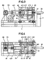
- FIGS. 3 and 4 represent a part mounted with a clearance J on a device for fractioning and evacuating the casting core, which differs from that shown in FIGS. 1 and 2 only by the presence of sleeve 413, forming a stop, on the slides 412, between the support plate 40 and the clamping plate 41.
- the parts 1 can be directly introduced from above, or, optionally, laterally, into the space thus formed between the two plates 40, 41, it being understood that the stop 402 existing on the support plate 40 limits the penetration of the part 1 in this space, without the need to use any blocking system. Note that on certain flat parts, the parts can be clamped directly, without interposing the clamping plate 41.
- the receiver 60 then being brought at the end of the stroke to the pneumatic hammer 20, by controlled action on the double eccentric 80 via the gear motor 81, the operation can then begin, since the hammer 21 of the pneumatic hammer 20 can - strike directly on the part, passing through the orifice 401 provided for this purpose.
- These hammering actions at high frequency, on the resonant assembly, consisting of the part 1 with its clamping plate 41 and of the chamber cylinder 50 at low pressure, cause, in the vicinity of the natural frequency of resonance of the system, a fractionation and takeoff of the nucleus. This resonance phenomenon can be controlled by acting on the inflation pressure of the chamber cylinder 50 and on the frequency of hammering.
- the sand resulting from the disintegration of the core flows by gravity between the side plates 61, 62 of said receiver and the side members of the frame 4.
- This sand can be discharged at the gradually by a conveyor belt.
- the swing frequency and its amplitude can, respectively, be adjusted, by action on a speed regulator and by action on the double eccentric.
- the disintegration action of the core fragments may be further increased, by providing a clearance J between the so-called clamping plate 41 and the part 1, by adding a sleeve 413 of appropriate length on the slides 412 ( Figures 3 and 4), or, as shown in Figures 5 and 6, by means of two jacks 55 and 56, mounted in opposition and passing through the connecting plate 43, the rod 551 of one of which is connected to the yoke 431 and whose rod 561 on the other comes to bear against the clamping plate 41, or directly against the part 1, to ensure, therein, a clearance J controlled in the horizontal plane; the clamping plate 41 then being secured to its slides by means of locking devices, incorporated in the slides 411.
- the jack 55 ensures the approach of the clamping plate as a function of the thickness of the part and the jack 56 only provides clearance J.
- this arrangement which corresponds to FIGS. 3 to 6, makes it possible to further increase the effect of inertia and, consequently, the collision between the pieces of core; it also facilitates the evacuation of sand, when dealing with parts with fairly complex internal architecture.
- the part 1 is fixed in the receiver 60 by means of a housing 90, mounted with clearance between the connecting plate 43 and the plate support 40, made integral with the side plates 61 and 62 of the receiver, or of the chassis (as shown in the figures), by means of four vertical links 73 fixed by means of elastic articulation 71.
- the part is locked against one of the short sides 91 of the housing, located towards the pneumatic hammer 20, by means of a chamber cylinder 50 bearing against the small opposite side 92 of said housing 90, with or without interposition, d 'a clamping plate 41 . It is thus possible to obtain a combined rocking of the part 1 by means of the receiver 60 and of the housing 90, by accompanying the latter with shocks due to the clearance provided between the housing and the connection plates 43 and d 'support 40.
- Figures 12 to 14 show a frame 1000,190 supporting a workpiece capsule 200 or a capsule support 1000 by means of links 500, springs 700 or crankshafts 180, actuated respectively by a crankshaft 300, one or more connecting rods 400 and a drive motor 600.
- the workpiece capsule 200 is connected to the frame 1000 by means of links 500, which can be common with those allowing the longitudinal swing, provided that their articulations are designed accordingly. (knee pads or double axis of articulation); the lateral swinging being ensured by the connecting rod 400 , driven by a reciprocating movement by means of the crankshaft 300. It is obvious, for the skilled person, that the frequency of the alternating swinging thus created and maintained by the engine 600, could be made random by simple random variation of the speed of rotation of said motor 600 ; which can be easily obtained by means of an electronic variator, the control of which is ensured accordingly.
- the workpiece capsule 200 is connected to the frame 1000 by means of the crankshaft 300, in direct engagement, on the underside of said capsule 200, and two rows of springs 700, arranged on each side of the crankshaft and ensuring the return to the vertical position of the capsule 200, while creating, with this, a vibrating system, which, combined with a random variation of the rotation speed of the crankshaft, obtained as indicated in the example above, will generate and maintain a random alternating swing of said workpiece carrier capsule 200.
- the longitudinal swing can be obtained by alternating sliding of the bearing 201, connecting the workpiece capsule 200 to the crankshaft 300, on the crankpin of said crankshaft, provided that the length thereof is predetermined accordingly to provide sufficient sliding freedom.
- the longitudinal swing and the transverse swing of the support 100 are combined in the circular movement of the crank pin 181 of the crankshafts 180 relative to the drive shaft 182 of these latter.
- the swing thus obtained can be made irregular and random, in this case too, by varying the speed of rotation of the crankshaft drive motor, using the means already mentioned in the other examples.
- the frequency of the longitudinal swing can be made, it also, random by random variation of the rotation speed of the motor assigned to this function.
- the method and the device according to the invention mainly concern the cleaning of the internal combustion engine cylinder heads, but nothing prevents their use for the elimination of the nucleus other foundry pieces with the same internal complexity, subject to minor adaptations.
Landscapes
- Engineering & Computer Science (AREA)
- Mechanical Engineering (AREA)
- Percussive Tools And Related Accessories (AREA)
- Cylinder Crankcases Of Internal Combustion Engines (AREA)
- Dental Preparations (AREA)
- Organic Low-Molecular-Weight Compounds And Preparation Thereof (AREA)
- Molds, Cores, And Manufacturing Methods Thereof (AREA)
Abstract
Description
L'invention concerne un procédé et un dispositif de débourrage de noyaux de coulée de pièces de fonderie.The invention relates to a method and a device for cleaning casting cores for foundry parts.
L'élimination des noyaux de coulée, sur des pièces de fonderie d'architecture assez complexe, exige, très souvent, de recourir à un marteau pneumatique, permettant de soumettre la pièce à des chocs répétés, susceptibles de rompre l'adhérence du sable sur les parois.Elimination of casting cores on architectural foundry pieces quite complex, very often requires the use of a hammer pneumatic, allowing the part to be subjected to repeated shocks, likely to break the adhesion of the sand on the walls.
A l'origine, ce travail s'effectuait en tenant le marteau pneumatique à la main, en s'en remettant à la dextérité et au savoir-faire de l'opérateur; il en résultait certaines disparités dans le résultat obtenu et la mise au rebut d'une proportion assez importante des pièces finies offrant un débourrage incomplet.Originally, this work was carried out by holding the pneumatic hammer at the hand, relying on the dexterity and expertise of the operator; this resulted in certain disparities in the result obtained and the scrapping of a fairly large proportion of the finished parts offering incomplete cleaning.
En vue de rationaliser cette opération et de mettre l'opérateur à l'abri des nuisances qui en résultent : bruit, poussière, il a été envisagé de recourir à des dispositifs tels que ceux décrits dans le brevet français n° 2.311.617 et le brevet européen n° 0.144.031. Ces dispositifs sont constitués, essentiellement, d'un châssis, sur lequel se fixe une ou plusieurs pièces à débourrer; le dit châssis étant soumis à des vibrations susceptibles de provoquer le décollage et le fractionnement des noyaux.In order to rationalize this operation and to protect the operator resulting nuisance: noise, dust, it has been considered to use devices such as those described in the French patent No. 2,311,617 and European Patent No. 0.144.031. These devices are essentially consisting of a chassis, on which one or more several pieces to be cleaned; the said chassis being subjected to vibrations likely to cause takeoff and fractionation of nuclei.
Pour accroítre encore le rendement de ce dispositif, il a été prévu, dans le brevet français 2.470.652, de disposer plusieurs châssis sur un carrousel polygonal, entraíné en rotation pas à pas devant un poste de chargement et un poste de déchargement diamétralement opposés.To further increase the efficiency of this device, provision has been made, in French patent 2,470,652, to have several chassis on a polygonal carousel, rotated step by step in front of a station diametrically opposite loading station and unloading station.
Toutefois, force est de remarquer que les vibrations appliquées ainsi régulièrement sur les pièces ne garantissent cependant pas un fractionnement suffisant du noyau, ni un décollage total de toutes les fractions de celui-ci. However, it must be noted that the vibrations applied in this way parts regularly do not guarantee splitting sufficient of the nucleus, nor a total takeoff of all fractions of it.
Il résulte de cette situation une certaine réticence des concepteurs à recourir à des architectures complexes, susceptibles de contrarier cette opération de débourrage, alors que ce serait cependant très souhaitable pour l'utilisation ultérieure de la pièce.It results from this situation a certain reluctance of the designers to resort to complex architectures, likely to contradict this cleaning operation, when it would however be very desirable for later use of the part.
Ce problème revêt une importance particulière pour les culasses de moteur à combustion interne, dont les plus complexes s'avèrent très souvent impossible à débourrer entièrement, avec ce que cela suppose comme perturbation sur les chaínes de fabrication et comme renoncement pour les concepteurs.This problem is of particular importance for cylinder heads. internal combustion engine, the most complex of which are very often impossible to completely disburse, with what this implies as a disruption on the production lines and as a waiver for designers.
La présente invention a pour but de remédier à ces inconvénients. Cette invention, telle qu'elle se caractérise, résout le problème consistant à définir un procédé et à créer des dispositifs avec lesquels les noyaux puissent être non seulement fragmentés, mais aussi totalement désagrégés, tout en provoquent un effet d'érosion entraínant le décollage de toutes les particules de sable, avant évacuation totale par gravité en une seule et même phase, de préférence, sans repositionnement de la pièce sur son support.The object of the present invention is to remedy these drawbacks. This invention, as it stands, solves the problem consisting of defining a process and creating devices with which kernels can be not only fragmented, but also totally disaggregated, while causing an eroding effect takeoff of all sand particles, before complete evacuation by gravity in a single phase, preferably without repositioning of the part on its support.
Le procédé selon l'invention se caractérise essentiellement en ce qu'il comprend une première opération qui consiste en
- l'application de chocs, à fréquence élevée, directement sur la pièce, alors que celle-ci est maintenue en appui contre un matelas pneumatique pour obtenir le fractionnement du noyau,; cette première opération étant suivre de deux autres opérations connues de l'art antérieur, et notamment du document EP-A-0144031, à savoir:
- balancement de la pièce selon un mouvement alternatif,
- élimination du Sable par gravité, au fur et à mesure de la désagrégation du noyau.
- the application of shocks, at high frequency, directly on the part, while the latter is held in abutment against an air mattress to obtain the fractionation of the core; this first operation being followed by two other operations known from the prior art, and in particular from document EP-A-0144031, namely:
- rocking of the part in an alternating movement,
- elimination of sand by gravity, as the nucleus disintegrates.
Les deux premières opérations du procédé selon l'invention permettent d'obtenir la désagrégation totale du noyau, la deuxième opération, à savoir le balancement alternatif de la pièce, permettant en outre d'obtenir un certain effet de Sablage de la pièce moulée. The first two operations of the method according to the invention allow to obtain the total disintegration of the nucleus, the second operation, namely alternative balancing of the workpiece, further enabling a certain sandblasting effect of the workpiece molded.
Selon un mode d'application du procédé, le balancement alternatif résulte de la combinaison d'un mouvement longitudinal alternatif à un mouvement transversal alternatif.According to one mode of application of the method, alternative balancing results from the combination of a reciprocating longitudinal movement an alternative transverse movement.
Selon une première variante du mode d'application ci-dessus, le mouvement transversal alternatif est appliqué dans un plan parallèle à celui dans lequel le mouvement longitudinal est appliqué.According to a first variant of the above application mode, the reciprocating transverse motion is applied in a parallel plane to the one in which the longitudinal movement is applied.
Selon une seconde variante du même mode d'application du procédé, le mouvement transversal alternatif est appliqué dans un plan perpendiculaire à celui dans lequel le mouvement longitudinal est appliqué.According to a second variant of the same mode of application of the method, the alternative transverse movement is applied in a perpendicular plane to the one in which the longitudinal movement is applied.
Selon une définition particulière du procédé, le balancement de la pièce s'effectue avec une amplitude et à une fréquence réglable respectivement de 0 à 10 cm et de 0 à 85 Hz.According to a particular definition of the process, the balancing of the work is performed with an amplitude and an adjustable frequency respectively from 0 to 10 cm and from 0 to 85 Hz.
Selon une autre définition particulière du procédé, le balancement de la pièce s'effectue en combinaison avec le rattrapage d'un jeu J, introduisant un effet d'inertie supplémentaire sur la masse sableuse.According to another particular definition of the method, the rocking of the piece is performed in combination with the take-up of a clearance J, introducing an additional inertial effect on the sandy mass.
Quels que soient le mode d'application et la définition du procédé, l'amplitude et la fréquence du balancement de la pièce varient, au cours du balancement, selon des règles déterminées en fonction de l'architecture interne de la pièce et de la dimension des cavités.Whatever the mode of application and the definition of the process, the amplitude and frequency of the swinging of the piece varies, swing course, according to rules determined according to the internal architecture of the room and the size of the cavities.
Selon une autre définition du procédé, la fréquence du balancement est irrégulière et aléatoire. According to another definition of the process, the frequency of rocking is irregular and random.
Un dispositif d'application du procédé de base selon l'invention se caractérise en ce que les chocs, à fréquence élevée, sont appliqués directement sur la pièce par l'intermédiaire d'un marteau pneumatique, fixé sur un support solidaire d'un bâti, disposé de façon à venir frapper directement la pièce par passage du marteau à travers un orifice ménagé, à cet effet, dans une plaque d'appui fixe, contre laquelle la pièce est maintenue par l'intermédiaire d'une plaque de serrage et d'un vérin à chambre, alimenté en basse pression, qui constitue le coussin d'air, en ce que le balancement de la pièce, qui s'effectue selon un mouvement alternatif horizontal, est obtenu par l'intermédiaire d'un récepteur, comportant la plaque d'appui, la plaque de serrage et le vérin de bridage, relié au bâti verticalement par quatre bielles et horizontalement par une bielle et un double excentrique, entraíné en rotation par l'intermédiaire d'un moto-réducteur, et en ce que l'élimination du sable par gravité s'obtient par le maintien en position verticale de la pièce, par mise en butée de celle-ci contre une butée mécanique solidaire de la plaque d'appui.A device for applying the basic method according to the invention is characterized in that the high frequency shocks are applied directly on the workpiece using a pneumatic hammer, fixed on a support integral with a frame, arranged so as to strike directly the workpiece by passing the hammer through an orifice formed for this purpose in a fixed support plate, against which the workpiece is held in place by a clamping plate and a chamber cylinder, supplied with low pressure, which constitutes the air cushion, in that the swinging of the part, which takes place according to a horizontal reciprocating movement is obtained through a receiver, comprising the support plate, the clamping plate and the clamping cylinder, connected to the frame vertically by four connecting rods and horizontally by a connecting rod and a double eccentric, rotated by means of a gear motor, and in this that the elimination of sand by gravity is obtained by maintaining in position vertical of the part, by abutting it against a mechanical stop secured to the support plate.
Le récepteur est constitué, préférentiellement, de deux plaques latérales, en forme de col de cygne, reliées entre elles par la plaque d'appui et par une plaque de liaison, supportant le vérin pneumatique à chambre prenant appui, d'une part, contre la plaque de liaison et contre la plaque de serrage montée par l'intermédiaire de coulisseaux sur quatre glissières reliant la plaque d'appui à la plaque de liaison, perpendiculairement à celles-ci.The receiver preferably consists of two side plates, swan neck shaped, connected together by the support plate and by a connecting plate, supporting the pneumatic cylinder with chamber bearing, on the one hand, against the connection plate and against the clamping plate mounted by means of slides on four slides connecting the support plate to the connection plate, perpendicular to them.
Les bielles verticales sont reliées aux plaques latérales par l'intermédiaire d'articulation élastiques.The vertical connecting rods are connected to the side plates via elastic joints.
La bielle horizontale est reliée à la plaque de liaison par l'intermédiaire d'une chape. The horizontal connecting rod is connected to the connection plate via of a screed.
Selon un autre mode de réalisation du dispositif selon l'invention exposé ci-dessus, le récepteur est équipé d'un boítier porte-pièce, monté avec un certain jeu entre la plaque de liaison et la plaque d'appui, supporté par quatre biellettes verticales fixées contre la paroi interne des plaques latérales par l'intermédiaire d'articulation élastique, ou directement sur le châssis par le même moyen.According to another embodiment of the device according to the invention described above, the receiver is fitted with a workpiece box, mounted with a certain clearance between the connection plate and the support plate, supported by four vertical rods fixed against the internal wall side plates by means of elastic articulation, or directly on the chassis by the same means.
Lorsqu'un jeu J doit être ménagé entre la plaque de serrage et la pièce, celui-ci est obtenu par le montage de manchons, de longueur déterminée en fonction de l'épaisseur de la pièce, sur les glissières, entre la plaque d'appui et la plaque de serrage, ou par l'intermédiaire de deux vérins, montés en opposition, traversant la plaque de liaison, dont la tige de l'un est fixée à la chape et dont la tige de l'autre vient en appui contre la plaque de serrage pour contrôler le jeu J à ménager entre la dite plaque de serrage et la pièce ; la dite plaque étant ensuite rendue solidaire de ses glissières par l'intermédiaire d'un système de blocage incorporé aux coulisseaux.When a clearance J must be made between the clamping plate and the part, this is obtained by mounting sleeves, of length determined according to the thickness of the part, on the slides, between the plate support and the clamping plate, or by means of two jacks, mounted in opposition, passing through the connecting plate, the rod of one of which is fixed to the yoke and the rod of the other of which comes to bear against the clamping plate for controlling the clearance J to be formed between said clamping plate and the part; said plate then being made integral with its slides by means of a blocking system incorporated in the slides.
Selon un mode de réalisation préférentiel du premier dispositif selon l'invention, deux récepteurs sont montés sur un même bâti, de part et d'autre d'un double excentrique unique, assurant, ainsi, le balancement simultané de deux pièces dans l'alignement de deux marteaux pneumatiques disposés à chacune des extrémités du bâti.According to a preferred embodiment of the first device according to the invention, two receivers are mounted on the same frame, both on the other a unique double eccentric, thus ensuring the balancing simultaneous two pieces in line with two hammers tires arranged at each end of the frame.
Selon la première variante d'application du procédé selon l'invention, le mouvement alternatif transversal est obtenu par l'intermédiaire d'un vilebrequin relié à une capsule porte-pièce par au moins une bielle en ce que ladite capsule porte-pièce est supportée par un bâti par l'intermédiaire de quatre biellettes s'articulant dans des plans perpendiculaires au vilebrequin et en ce que la fréquence du balancement alternatif est rendue irrégulière et aléatoire par variation correspondante de la vitesse de rotation du moteur d'entraínement du vilebrequin.According to the first variant of application of the method according to the invention, the transverse reciprocating movement is obtained through a crankshaft connected to a workpiece holder by at least a connecting rod in that said work-holding capsule is supported by a built by means of four links articulated in planes perpendicular to the crankshaft and in that the frequency of swaying alternative is made irregular and random by variation corresponding to the speed of rotation of the drive motor crankshaft.
Selon la seconde variante d'application du procédé selon l'invention, le mouvement alternatif transversal est obtenu dans un plan perpendiculaire au mouvement longitudinal par l'intermédiaire d'un vilebrequin relié à la capsule porte-pièce par au moins un palier fixé sous cette dernière, et de ressorts, interposés verticalement entre la capsule porte-pièce et le bâti, et en ce que la fréquence du balancement alternatif est rendue irrégulière et aléatoire par variation correspondante de la vitesse de rotation du moteur d'entraínement du vilebrequin.According to the second variant of application of the method according to the invention, the transverse reciprocating movement is obtained in a perpendicular plane longitudinal movement via a crankshaft connected to the workpiece holder by at least one bearing fixed under the latter, and springs, interposed vertically between the capsule workpiece and the frame, and in that the frequency of the alternating swing is made irregular and random by corresponding variation the rotational speed of the crankshaft drive engine.
Le vilebrequin est disposé dans le plan médian longitudinal de la capsule porte-pièce alors que les ressorts sont répartis en deux rangées disposées symétriquement par rapport au vilebrequin.The crankshaft is arranged in the longitudinal median plane of the capsule workpiece carrier while the springs are divided into two rows arranged symmetrically with respect to the crankshaft.
Selon un autre mode de réalisation de la première variante d'application du procédé selon l'invention, le mouvement longitudinal alternatif et le mouvement transversal alternatif sont combinés dans un même mouvement assurant le balancement alternatif d'ensemble par l'intermédiaire de deux vilebrequins disposés verticalement entre un bâti et un support de capsule porte-pièce, et en ce que la fréquence du balancement alternatif est rendue irrégulière et aléatoire par variation correspondante de la vitesse de rotation du moteur d'entraínement des vilebrequins.According to another embodiment of the first application variant of the method according to the invention, the reciprocating longitudinal movement and the reciprocating transverse movement are combined in a same movement ensuring the overall alternative swing by through two crankshafts arranged vertically between a frame and a workpiece holder support, and in that the frequency of alternative swing is made irregular and random by variation corresponding to the speed of rotation of the drive motor crankshafts.
quels que soient les variantes d'application du procédé et leurs modes de réalisation, la variation de vitesse du moteur d'entraínement de l'excentrique ou du vilebrequin est obtenue par l'intermédiaire d'un variateur électronique piloté.whatever the application variants of the process and their modes of realization, the speed variation of the drive motor of the eccentric or the crankshaft is obtained through a electronic dimmer controlled.
Les avantages obtenus, grâce à cette invention, consistent essentiellement en ceci que des pièces creuses, d'architecture complexe, telles que des culasses de moteur à explosion, peuvent être réalisées par moulage, sans risque de difficulté d'élimination de la totalité du noyau, tout en améliorant l'état de surface des parois par effet de sablage, favorisant, ainsi, l'écoulement ultérieur des fluides liquides ou gazeux, destinés à circuler dans les cavités ménagées à l'intérieur de la pièce, selon une architecture même très complexe.The advantages obtained with this invention consist essentially of in that hollow rooms, of complex architecture, such as internal combustion engine cylinder heads, can be made by molding, without risk of difficulty in removing all of the core, while improving the surface condition of the walls by sanding effect, thus promoting the subsequent flow of liquid fluids or gaseous, intended to circulate in the cavities formed inside of the room, according to a very complex architecture.
D'autres caractéristiques et avantages apparaítront dans la description qui va suivre d'un mode de réalisation de l'invention, destiné au débourrage de culasses de moteurs, donné à titre d'exemple non limitatif au regard des dessins annexés sur lesquels :
- la figure 1 représente une vue de face d'un dispositif à mouvement alternatif longitudinal, sans jeu longitu dinal, appliquant le procédé de base,
- la figure 2 représente une vue de dessus du dispositif selon la figure 1,
- la figure 3 représente une vue de face d'un dispositif avec jeu longitudinal,
- la figure 4 représente une vue de dessus du dispositif selon la figure 3,
- la figure 5 représente une vue de face d'une variante de réalisation du dispositif à mouvement alternatif longitudinal avec jeu longitudinal,
- la figure 6 représente une vue de dessus du dispositif selon la figure 5,
- la figure 7 représente une vue de face d'un mode de réalisation particulier du dispositif à mouvement alternatif horizontal avec jeu longitudinal,
- la figure 8 représente une vue de dessus du dispositif selon la figure 7,
- les figures 9, 10 et 11 représentent, respectivement, une vue de face, une vue de dessus et une vue de côté d'un dispositif à deux postes,
- la figure 12 représente une vue de face schématique du dispositif de débourrage selon un mode de réalisation correspondant à la première variante d'application du procédé,
- la figure 13 représente une vue de face schématique du dispositif de débourrage selon un mode de réalisation correspondant à la seconde variante d'application du procédé,
- la figure 14 représente une vue de côté schématique en perspective, du dispositif de débourrage selon la première variante d'application du procédé selon l'invention, correspondant à un mode de réalisation particulier de celle-ci.
- FIG. 1 represents a front view of a device with longitudinal reciprocating movement, without longitudinal play, applying the basic method,
- FIG. 2 represents a top view of the device according to FIG. 1,
- FIG. 3 represents a front view of a device with longitudinal play,
- FIG. 4 represents a top view of the device according to FIG. 3,
- FIG. 5 represents a front view of an alternative embodiment of the device with longitudinal reciprocating movement with longitudinal clearance,
- FIG. 6 represents a top view of the device according to FIG. 5,
- FIG. 7 represents a front view of a particular embodiment of the device with horizontal reciprocating movement with longitudinal play,
- FIG. 8 represents a top view of the device according to FIG. 7,
- FIGS. 9, 10 and 11 represent, respectively, a front view, a top view and a side view of a device with two stations,
- FIG. 12 represents a schematic front view of the cleaning device according to an embodiment corresponding to the first variant of application of the method,
- FIG. 13 represents a schematic front view of the cleaning device according to an embodiment corresponding to the second variant of application of the method,
- FIG. 14 represents a schematic side view in perspective, of the cleaning device according to the first variant of application of the method according to the invention, corresponding to a particular embodiment of the latter.
Les figures 1 et 2 représentent une pièce 1, montée sur un dispositif
de fractionnement et d'évacuation du noyau de coulée de pièces de
fonderie selon l'invention, comportant un marteau pneumatique 20 à
marteau 21, fixé sur un support 3 solidaire d'un bâti 4 disposé de façon
à venir frapper directement la pièce 1 par passage du marteau 21 à
travers un orifice 401, ménagé, à cet effet, dans une plaque d'appui
fixe 40 à butée verticale 402, contre laquelle la pièce 1 est maintenue
par l'intermédiaire d'une plaque de serrage 41 soumise à l'action d'un
vérin à chambre 50, alimenté en basse pression, constituant un coussin
d'air ; la dite plaque d'appui 40 et la dite plaque de serrage 41 font
partie d'un récepteur 60, relié au bâti 4 verticalement par quatre
bielles 70 à articulation élastique 71 et horizontalement par une
bielle 72 reliée, d'une part, à un double excentrique 80 entraíné par un
moto-réducteur à vitesse variable 81 et, d'autre part, par l'intermédiaire
d'une chape 431 à une plaque de liaison 43 supportant le vérin à
chambre 50, reliant transversalement, en combinaison avec la plaque
d'appui 40, deux plaques latérales en forme de col de cygne 61, 62 ; la
plaque de serrage 41 est montée, par l'intermédiaire de coulisseaux
411, sur quatre glissières 412 reliant la plaque d'appui 40 à la plaque
de liaison 43. Figures 1 and 2 show a
Les figures 3 et 4 représentent une pièce montée avec un jeu J sur un
dispositif de fractionnement et d'évacuation du noyau de coulée, qui
ne diffère de celui représenté sur les figures 1 et 2 que par la présence
de manchon 413, formant butée, sur les glissières 412, entre la plaque
d'appui 40 et la plaque de serrage 41. FIGS. 3 and 4 represent a part mounted with a clearance J on a device for fractioning and evacuating the casting core, which differs from that shown in FIGS. 1 and 2 only by the presence of
En examinant plus en détail les figures 1 et 2, on remarque que, sous
réserve que la longueur utile de la bielle 72 ait été préalablement réglée
afin d'obtenir un écartement nécessaire et suffisant entre la plaque
d'appui 40 et la plaque de serrage 41, pour une longueur à vide déterminée,
du vérin à chambre 50, les pièces 1 peuvent être directement
introduites par le dessus, ou, éventuellement, latéralement, dans
l'espace ainsi ménagé entre les deux plaques 40, 41, étant entendu
que la butée 402 existant sur la plaque d'appui 40 limite la pénétration
de la pièce 1 dans cet espace, sans qu'il soit nécessaire de recourir
à aucun système de blocage. A noter que sur certaines pièces de
forme plane, le serrage des pièces peut s'effectuer directement, sans
interposition de la plaque de serrage 41. By examining Figures 1 and 2 in more detail, it will be noted that, provided that the useful length of the connecting
Le récepteur 60 étant alors amené en fin de course vers le marteau
pneumatique 20, par action contrôlée sur le double excentrique 80
par l'intermédiaire du moto-réducteur 81, l'opération peut alors commencer,
puisque le marteau 21 du marteau pneumatique 20 peut-frapper
directement sur la pièce, en passant par l'orifice 401 prévu à cet
effet. Ces actions de martelage, à fréquence élevée, sur l'ensemble
résonnant, constitué de la pièce 1 avec sa plaque de serrage 41 et du
vérin à chambre 50 à basse pression, provoquent, au voisinage de la
fréquence propre de résonance du système, un fractionnement et un
décollage du noyau. Ce phénomène de résonance peut être contrôlé
par action sur la pression de gonflage du vérin à chambre 50 et sur la
fréquence du martelage.The
Cette opération étant terminée, la désagrégation complète des morceaux
de noyau peut alors être entreprise, par mise en oeuvre du balancement
par va-et-vient de la pièce 1 par action sur le récepteur 60
supporté par les bielles verticales 70, par mise en marche continue du
moto-réducteur 81 entraínant le double excentrique 80 qui communique,
au dit récepteur 60, un mouvement horizontal alternatif, de
course et de fréquence déterminées par l'intermédiaire de la bielle 72
et de la chape 431 fixée perpendiculairement à la plaque de liaison
43. Les morceaux de noyau, résultant de la fragmentation produite
lors de l'opération précédente, subissant des effets d'inertie, qui provoquent,
par entrechoquement, leur désagrégation progressive ; opération
qui entraíne une certaine érosion des aspérités qui peuvent
subsister dans les cavités inaccessibles et un décollement complet
des particules sableuses les plus adhérentes, par un effet de "sablage"
bien connu en mécanique.This operation being completed, the complete disaggregation of the pieces of core can then be undertaken, by implementing the swinging back and forth of the
Sous réserve que la pièce 1 soit présentée en conséquence sur le récepteur,
le sable résultant de la désagrégation du noyau s'écoule par
gravité entre les plaques latérales 61, 62 du dit récepteur et les longerons
du bâti 4. Ce sable peut être évacué au fur et à mesure par une
bande transporteuse. La fréquence du balancement et son amplitude
pourront, respectivement, être réglées, par action sur un régulateur
de vitesse et par action sur le double excentrique.Provided that the
Dans certains cas, l'action de désagrégation des fragments de noyau
pourra être encore accrue, par ménagement d'un jeu J entre la plaque
dite de serrage 41 et la pièce 1, par adjonction de manchon 413 de longueur
appropriée sur les glissières 412 (figures 3 et 4), ou, comme représenté
sur les figures 5 et 6, par l'intermédiaire de deux vérins 55 et
56, montés en opposition et traversant la plaque de liaison 43, dont la
tige 551 de l'un est reliée à la chape 431 et dont la tige 561 de l'autre
vient en appui contre la plaque de serrage 41, ou directement contre
la pièce 1, pour assurer, à celle-ci, un jeu J contrôlé dans le plan horizontal
; la plaque de serrage 41 étant ensuite solidarisée à ses glissières
par l'intermédiaire de dispositifs de blocage, incorporés aux
coulisseaux 411. Ainsi, le vérin 55 assure l'approche de la plaque de
serrage en fonction de l'épaisseur de la pièce et la vérin 56 assure uniquement
le jeu J. cette disposition, qui correspond aux figures 3 à 6,
permet d'accroítre, encore, l'effet d'inertie et, par conséquent, l'entrechoquement
entre les morceaux de noyau; elle facilite, aussi,
l'évacuation du sable, lorsqu'on a affaire à des pièces à architecture
interne assez complexe.In some cases, the disintegration action of the core fragments may be further increased, by providing a clearance J between the so-called
Selon le mode de réalisation particulier de l'invention, représenté sur
les figures 7 et 8, la pièce 1 se fixe dans le récepteur 60 par l'intermédiaire
d'un boítier 90, monté avec jeu entre la plaque de liaison 43 et
la plaque d'appui 40, rendu solidaire des plaques latérales 61 et 62 du
récepteur, ou du châssis (comme représenté sur les figures), par l'intermédiaire
de quatre biellettes verticales 73 fixées par l'intermédiaire
d'articulation élastique 71. La pièce est bloquée contre l'un des
petits côtés 91 du boítier, situé vers le marteau pneumatique 20, par
l'intermédiaire d'un vérin à chambre 50 prenant appui contre le petit
côté opposé 92 du dit boítier 90, avec interposition, ou non, d'une
plaque de serrage 41. Il est possible, ainsi, d'obtenir un balancement
combiné de la pièce 1 par l'intermédiaire du récepteur 60 et du boítier
90, en accompagnant celui-ci de chocs dûs au jeu ménagé entre le boítier
et les plaques de liaison 43 et d'appui 40. According to the particular embodiment of the invention, shown in Figures 7 and 8, the
On comprend qu'il soit intéressant de combiner deux dispositifs, afin qu'ils utilisent, en commun, le double excentrique et son moteur d'entraínement, comme représenté sur les figures 9, 10 et 11.We understand that it is interesting to combine two devices, in order that they use, in common, the double eccentric and its drive motor, as shown in Figures 9, 10 and 11.
Les figures 12 à 14 représentent un bâti 1000,190 supportant une capsule
porte-pièce 200 ou un support de capsule 1000 par l'intermédiaire
de biellettes 500, de ressorts 700 ou de vilebrequins 180, actionnés
respectivement par un vilebrequin 300, une ou plusieurs bielles 400
et un moteur d'entraínement 600. Figures 12 to 14 show a
En examinant plus particulièrement la figure 12, on remarque que la
capsule porte-pièce 200 est reliée au châssis 1000 par l'intermédiaire
de biellettes 500, qui peuvent être communes avec celles permettant
le balancement longitudinal, sous réserve que leurs articulations
soient conçues en conséquence (genouillères ou double axe d'articulation)
; le balancement latéral étant assuré par la bielle 400, animée
d'un mouvement alternatif par l'intermédiaire du vilebrequin 300. Il
est évident, pour l'homme de métier, que la fréquence du balancemnt
alternatif ainsi créée et entretenue par le moteur 600, pourra être rendue
aléatoire par simple variation aléatoire de la vitesse de rotation
dudit moteur 600 ; ce qui peut être aisément obtenu par l'intermédiaire
d'un variateur électronique, dont le pilotage est assuré en conséquence. By examining more particularly FIG. 12, it is noted that the
En se reportant à la figure 13, on remarque que, dans ce mode de réalisation,
la capsule porte-pièce 200 est reliée au bâti 1000 par l'intermédiaire
du vilebrequin 300, en prise directe, sur le dessous de ladite
capsule 200, et de deux rangées de ressorts 700, disposées de
chaque côté du vilebrequin et assurant le rappel en position verticale
de la capsule 200, tout en créant, avec celle-ci, un système vibrant,
qui, combiné à une variation aléatoire de la vitesse de rotation du vilebrequin,
obtenue comme indiqué à l'exemple ci-dessus, générera et
entretiendra un balancement alternatif aléatoire de ladite capsule
porte-pièce 200. Dans ce mode de réalisation, le balancement longitudinal
peut être obtenu par coulissement alternatif du palier 201, reliant
la capsule porte-pièce 200 au vilebrequin 300, sur le maneton
dudit vilebrequin, sous réserve que la longueur de celui-ci soit prédéterminée
en conséquence pour offrir une liberté de coulissement suffisante.Referring to FIG. 13, it is noted that, in this embodiment, the
En examinant maintenant la figure 3, on remarque que, dans ce mode
de réalisation, le balancement longitudinal et le balancement transversal
du support 100 sont combinés dans le déplacement circulaire
du maneton 181 des vilebrequins 180 par rapport à l'arbre d'entraínement
182 de ces derniers. Le balancement ainsi obtenu peut être rendu
irrégulier et aléatoire, dans ce cas aussi, par variation de la vitesse
de rotation du moteur d'entraínement des vilebrequins, utilisant le
moyen déjà évoqué dans les autres exemples.By now examining FIG. 3, it is noted that, in this embodiment, the longitudinal swing and the transverse swing of the
Il faut souligner que, dans les exemples représentés aux figures 12 et 13, la fréquence du balancement longitudinal peut être rendue, elle aussi, aléatoire par variation aléatoire de la vitesse de rotation du moteur affecté à cette fonction.Note that in the examples shown in Figures 12 and 13, the frequency of the longitudinal swing can be made, it also, random by random variation of the rotation speed of the motor assigned to this function.
Le procédé et le dispositif, selon l'invention, concernent, principalement, le débourrage des culasses de moteur à combustion interne, mais rien ne s'oppose à leur utilisation pour l'élimination du noyau d'autres pièces de fonderie présentant la même complexité interne, sous réserve d'adaptations mineures.The method and the device according to the invention mainly concern the cleaning of the internal combustion engine cylinder heads, but nothing prevents their use for the elimination of the nucleus other foundry pieces with the same internal complexity, subject to minor adaptations.
Claims (22)
- Method for fractioning and evacuating foundry parts from the smelting core and including the following successive operations :applying high frequency impacts directly to the part (1) when the latter is kept in support against a pneumatic cushion so as to fraction the core,alternative horizontal balancing of the part (1) so as to obtain the total disintegration of the core and a sand blasting effect of the internal walls of said part (1),elimination of the sand by means of gravity as the core gradually disintegrates.
- Method according to claim 1, wherein the alternative balancing results from combining an alternative longitudinal movement with an alternative transversal movement.
- Method according to claim 2, characterised in that the alternative transversal movement is applied inside a plane parallel to the one in which the longitudinal movement is applied.
- Method according to claim 2, characterised in that the alternative transversal movement is applied inside a plane perpendicular to the one in which the longitudinal movement is applied.
- Method according to claim 1 or 2, characterised in the alternative balancing of the part (1) accompanies the elimination of play (J) introducing an additional inertia effect on the sandy mass.
- Method according to claim 1 or 2, characterised in that the balancing of the part is carried out with an amplitude able to be adjusted from 0 to 10 cm.
- Method according to claim 1 or 2, characterised in that the amplitude and frequency of balancing vary during the latter according to rules determined according to the internal structure of the part (1) and the dimension of the cavities.
- Method according to claim 7, characterised in that the frequency of balancing is between 0 and 85 Hz.
- Method according to claim 1 or 2, characterised in that the frequency of balancing is irregular or random.
- Device for fractioning and evacuating foundry parts from the smelting core for implementing the method according to the preceding claims, characterised in that it comprises a pneumatic hammer (20) secured to a support (3) integral with a frame (4) and disposed so as to directly strike the part via the passage of the hammer (21) through an orifice (401) provided to this effect in a fixed support plate (40) against which the part (1) is supported by means of a clamping plate (41) and a chamber jack (50) fed at low pressure and constituting an air cushion, said support plate (40) and said clamping plate (41) forming part of a receiver (60) vertically connected to the frame (4) by four connecting rods (70) and by a connecting rod (72) activated by a double cam (80) driven in rotation by means of a back-geared motor (81), the part (1) being kept in a vertical position by abutting against a mechanical stop (402) integral with the support plate (40).
- Device according to claim 10, characterised in that the receiver (60) is made up of two lateral plates with the shape of a swan neck (61, 62) interconnected by the support plate (40) and by a linking plate (43) supporting a pneumatic chamber jack (50) taking support on firstly against the linking plate (43) and secondly against the clamping plate (41) mounted by means of sliding blocks (411) on four slides (412) connecting the support plate (40) to the linking plate (43) perpendicular to the latter.
- Device according to claim 10, characterised in that the vertical connecting rods (70) are connected to the lateral plates (61, 62) by means of elastic joints.
- Device according to claim 10, characterised in that the horizontal connecting rod (72) is connected to the linking plate (43) by a clevis (431).
- Device according to claim 10, characterised in that two receivers (60) are mounted on a given frame on both sides of a sole double cam (80), thus ensuring the simultaneous balancing of two parts (1) in the alignment of two pneumatic hammers (20) disposed at each of the ends of the frame.
- Device according to claim 10, characterised in that, when play (J) needs to be fitted between the clamping plate (41) and the part (1), the latter is obtained by sleeve mounting (413) having a length determined according to the thickness of the part (1) on slides (412) between the support plate (40) and the clamping plate (41).
- Device according to claim 10, characterised in that, when play (J) needs to be fitted between the clamping plate (41) and the part (1), the latter is obtained by means of two jacks (55 and 56) mounted in opposition and traversing the linking plate (43), the rod of one (551) being connected to the clevis (431), the rod of the other (561) controlling the introduction of play (J) between the part (1) and the clamping plate (41), the latter (41) then being rendered integral with its slides (412) via locking carried out at the level of the slide blocks (411).
- Device according to claim 10, characterised in that the part (1) is mounted in the receiver (60) by means of a box (90) disposed with play between the linking plate (43) and the support plate (40) joined with respect to the lateral plates (61 and 62) of the receiver (60) by means of vertical connecting rods (73) with an elastic joint (71), said part (1) being rendered immobile against one of the small sides (91) of the box (90) situated towards the pneumatic hammer (20) by means of at least one chamber jack (50) taking support against the side (92) opposite the box.
- Device according to claim 10, characterised in that, so as to ensure the transversal alternative movement, it comprises a crank (300) connected to a part holder capsule (200) by at least one connecting rod (400), said part holder capsule (200) being supported by a frame (1000) by means of four small connecting rods linked in planes perpendicular to the crank (300) which is driven by a motor (600) whose variation of the speed of rotation is able to make the frequency of the alternative balancing irregular and random.
- Device according to claim 10, characterised in that, so as to ensure the transversal alternative movement, it comprises a crankshaft (300) connected to the part holder capsule (200) by at least one bearing (201) fixed under the latter, and springs (700) inserted vertically between said part holder capsule (200) and the frame (1000), the crankshaft (300) being driven by a motor (600) whose variation of the speed of rotation is able to make the frequency of the transversal alternative balancing irregular and random.
- Device according to claim 19, characterised in that the crankshaft (300) is disposed inside the median longitudinal plane of the part holder capsule (200) when the springs (700) are distributed into two rows disposed symmetrically with respect to the crankshaft (300).
- Device according to claim 10, characterised in that, so as to ensure a combined alternative longitudinal movement and an alternative transversal movement in a single movement, it comprises two crankshafts (180) disposed vertically between a frame (190) and a part holder capsule support (100), the frequency of alternative balancing being rendered irregular and random by the corresponding variation of the speed of rotation of the motor for driving the crankshafts (180).
- Device according to one of claims 10 to 21, characterised in that the variation of the speed of the drive motor (81,600) is obtained by means of a controlled electronic variable-speed drive unit.
Applications Claiming Priority (5)
| Application Number | Priority Date | Filing Date | Title |
|---|---|---|---|
| FR9101385 | 1991-02-07 | ||
| FR9101385A FR2672525B1 (en) | 1991-02-07 | 1991-02-07 | METHOD AND DEVICE FOR CLEANING CASTING CORES OF FOUNDRY PARTS. |
| FR9110389A FR2680327B1 (en) | 1991-08-14 | 1991-08-14 | IMPROVEMENTS IN PROCESSES AND DEVICES FOR CLEARING CASTING CORES OF FOUNDRY PIECES. |
| FR9110389 | 1991-08-14 | ||
| PCT/FR1992/000095 WO1992013663A1 (en) | 1991-02-07 | 1992-02-04 | Method and devices for decoring castings |
Publications (2)
| Publication Number | Publication Date |
|---|---|
| EP0524302A1 EP0524302A1 (en) | 1993-01-27 |
| EP0524302B1 true EP0524302B1 (en) | 1999-10-20 |
Family
ID=26228498
Family Applications (1)
| Application Number | Title | Priority Date | Filing Date |
|---|---|---|---|
| EP92906406A Expired - Lifetime EP0524302B1 (en) | 1991-02-07 | 1992-02-04 | Method and devices for decoring castings |
Country Status (10)
| Country | Link |
|---|---|
| US (1) | US5460219A (en) |
| EP (1) | EP0524302B1 (en) |
| JP (1) | JP3056526B2 (en) |
| KR (1) | KR100227743B1 (en) |
| AT (1) | ATE185725T1 (en) |
| AU (1) | AU1344692A (en) |
| CA (1) | CA2079996C (en) |
| DE (1) | DE69230160T2 (en) |
| ES (1) | ES2142316T3 (en) |
| WO (1) | WO1992013663A1 (en) |
Cited By (1)
| Publication number | Priority date | Publication date | Assignee | Title |
|---|---|---|---|---|
| DE202007018558U1 (en) | 2007-05-08 | 2008-11-13 | August Mössner GmbH & Co. KG | Vibrating device for removing the core sand from hollow castings |
Families Citing this family (18)
| Publication number | Priority date | Publication date | Assignee | Title |
|---|---|---|---|---|
| FR2699840B1 (en) * | 1992-12-28 | 1995-02-10 | Peugeot | Machine for sanding castings. |
| FR2711931B1 (en) * | 1993-11-05 | 1996-02-09 | Dimafond | Improved device for cleaning the cores of casting of foundry parts. |
| FR2730436B1 (en) * | 1995-02-13 | 1997-05-09 | Peugeot | METHOD AND DEVICE FOR DESSABLING A FOUNDRY PIECE |
| IT1308141B1 (en) * | 1999-03-17 | 2001-11-29 | Fi Me S R L Societa Unipersona | GROUNDWORK FOR FOUNDRY JETS. |
| US7094476B2 (en) * | 2002-06-27 | 2006-08-22 | Asahi Tec Corporation | Surface-treated product, surface-treatment method, and surface-treatment apparatus |
| JP4703947B2 (en) * | 2002-06-27 | 2011-06-15 | 旭テック株式会社 | Oscillator |
| FR2850305B1 (en) * | 2003-01-23 | 2005-03-18 | Marcel Massin | AUTOMATED DELIVERY SYSTEM AND UNLOADING DEVICE |
| FR2850890B1 (en) * | 2003-02-10 | 2006-09-15 | Remi Dupuis | DEVICE FOR DESSABLING HOLLOW FOUNDRY PIECES |
| CN100346906C (en) * | 2005-03-24 | 2007-11-07 | 北京铝镁泰和铸机设备科技有限公司 | Segmented cam demoulding device and its application method |
| WO2007114377A1 (en) * | 2006-03-30 | 2007-10-11 | Asahi Tec Corporation | Vertically shaking working device |
| US7712513B1 (en) | 2006-04-04 | 2010-05-11 | Carrier Vibrating Equipment Co. | System and method for controlling casting shakeout retention |
| JP5772488B2 (en) * | 2011-10-19 | 2015-09-02 | 日産自動車株式会社 | Core sand removal method |
| US9109531B2 (en) | 2012-01-09 | 2015-08-18 | Honda Motor Co., Ltd. | Method for testing casting quality and apparatus therefor |
| SI24307A (en) | 2013-03-29 | 2014-09-30 | Rc Simit D.O.O. | Boring of sand cores from castings |
| CN103231042A (en) * | 2013-04-25 | 2013-08-07 | 吴江市董鑫塑料包装厂 | Stripping device |
| CN106001519B (en) * | 2016-07-08 | 2018-10-02 | 芜湖永达科技有限公司 | A kind of cylinder body shake core machine |
| JP2020102939A (en) * | 2018-12-21 | 2020-07-02 | 日本電産株式会社 | Actuator |
| KR102147091B1 (en) * | 2019-01-11 | 2020-08-24 | 이정수 | Vibrating separator and system for separating casting using thereof |
Family Cites Families (11)
| Publication number | Priority date | Publication date | Assignee | Title |
|---|---|---|---|---|
| US3162910A (en) * | 1961-06-26 | 1964-12-29 | Simplicity Eng Co | Apparatus for shaking out foundry flasks |
| US4185681A (en) * | 1978-06-22 | 1980-01-29 | Conveyersmith, Inc. | Ceramic knock-off apparatus for removing ceramic from investment casting molds |
| CH654230A5 (en) * | 1981-05-27 | 1986-02-14 | Werner Lueber | DEVICE FOR REMOVING THE CORE SAND FROM CAST PIECES. |
| DE3236709A1 (en) * | 1982-10-04 | 1984-04-05 | R.S. Rösler Gleitschlifftechnik und technische Keramik GmbH, 8623 Staffelstein | Apparatus for decoring castings |
| DE3239262A1 (en) * | 1982-10-23 | 1984-04-26 | Alb. Klein Gmbh & Co Kg, 5241 Niederfischbach | Method and device for decoring castings |
| IT1157143B (en) * | 1982-12-14 | 1987-02-11 | Fataluminium Spa | GROUNDING DEVICE FOR CABLE METAL JETS |
| DE3341894C1 (en) * | 1983-11-19 | 1985-03-14 | Bayerische Motoren Werke AG, 8000 München | Device for coring castings by vibrations |
| US4718473A (en) * | 1985-01-25 | 1988-01-12 | General Kinematics Corporation | Vibratory stress relief apparatus |
| DE3728687A1 (en) * | 1987-08-27 | 1989-03-09 | Froelich & Kluepfel Druckluft | METHOD AND DEVICE FOR COREING CASTING PIECES |
| DE8900887U1 (en) * | 1988-01-27 | 1989-05-03 | "F. U. K." Froelich & Kluepfel Drucklufttechnik Gmbh & Co Kg, 5600 Wuppertal, De | |
| DE58906124D1 (en) * | 1988-01-27 | 1993-12-16 | Froelich & Kluepfel Druckluft | Device for coring castings. |
-
1992
- 1992-02-04 CA CA002079996A patent/CA2079996C/en not_active Expired - Fee Related
- 1992-02-04 AU AU13446/92A patent/AU1344692A/en not_active Abandoned
- 1992-02-04 US US07/934,540 patent/US5460219A/en not_active Expired - Fee Related
- 1992-02-04 WO PCT/FR1992/000095 patent/WO1992013663A1/en active IP Right Grant
- 1992-02-04 KR KR1019920702456A patent/KR100227743B1/en not_active IP Right Cessation
- 1992-02-04 ES ES92906406T patent/ES2142316T3/en not_active Expired - Lifetime
- 1992-02-04 AT AT92906406T patent/ATE185725T1/en not_active IP Right Cessation
- 1992-02-04 JP JP4505537A patent/JP3056526B2/en not_active Expired - Lifetime
- 1992-02-04 EP EP92906406A patent/EP0524302B1/en not_active Expired - Lifetime
- 1992-02-04 DE DE69230160T patent/DE69230160T2/en not_active Expired - Fee Related
Cited By (3)
| Publication number | Priority date | Publication date | Assignee | Title |
|---|---|---|---|---|
| DE202007018558U1 (en) | 2007-05-08 | 2008-11-13 | August Mössner GmbH & Co. KG | Vibrating device for removing the core sand from hollow castings |
| DE102007022043A1 (en) | 2007-05-08 | 2008-11-13 | August Mössner GmbH & Co. KG | Vibrating device and method for removing the core sand from hollow castings |
| EP1995002A2 (en) | 2007-05-08 | 2008-11-26 | August Moessner GmbH & Co. KG. | Shaking device and method for removing core sand from hollow moulds |
Also Published As
| Publication number | Publication date |
|---|---|
| ES2142316T3 (en) | 2000-04-16 |
| US5460219A (en) | 1995-10-24 |
| CA2079996C (en) | 2000-04-25 |
| JP3056526B2 (en) | 2000-06-26 |
| ATE185725T1 (en) | 1999-11-15 |
| JPH05506407A (en) | 1993-09-22 |
| AU1344692A (en) | 1992-09-07 |
| KR100227743B1 (en) | 1999-11-01 |
| EP0524302A1 (en) | 1993-01-27 |
| CA2079996A1 (en) | 1992-08-08 |
| DE69230160D1 (en) | 1999-11-25 |
| DE69230160T2 (en) | 2000-08-17 |
| WO1992013663A1 (en) | 1992-08-20 |
Similar Documents
| Publication | Publication Date | Title |
|---|---|---|
| EP0524302B1 (en) | Method and devices for decoring castings | |
| EP0652063B1 (en) | Knock-out device for casting cores | |
| EP0099791B1 (en) | Equipment for extraction of stone,marble or granite,especially from quarries and for roughing and squaring it | |
| FR2462943A1 (en) | VIBRATING MACHINE INTENDED TO BE MOUNTED ON A FIXED SUPPORT | |
| CA1041254A (en) | Method and apparatus for vibration cleaning of workpieces such as engine blocks | |
| CA2513693C (en) | Automated decoring system and decoring device | |
| EP0620043A2 (en) | Desintegrator for solid objects | |
| FR2672525A1 (en) | Method and device for stripping the dross (casting) cores of foundry articles (castings) | |
| WO2012098319A1 (en) | Crankshaft, and method for manufacturing said crankshaft | |
| FR2901162A1 (en) | MARKING METHOD, MARKER DEVICE ACTIVATING A VIBRATOR SYSTEM AND USING THE DEVICE IN A CLEARING MACHINE | |
| FR2994396A1 (en) | Device, useful for cleaning a casting, comprises a frame having two parallel webs, and clamping device including a rotatable portion that rotates with the casting and a rotating unit about the axis perpendicular to two parallel webs | |
| EP4000837B1 (en) | Machine for construction site with offset vibration source | |
| FR2730436A1 (en) | Removing sand from foundry components | |
| FR2680327A1 (en) | Improvements to methods and devices for decoring foundry component (casting) casting cores | |
| FR2850890A1 (en) | Blast cleaning device for hollow casting unit e.g. engine block, of automobile, has elastic suspension system to supply mechanical power necessary to vibrate one vibrating shell, when shell is excited to resonance frequency | |
| CA2300504A1 (en) | Procedure for cleaning or decoring a cast piece | |
| FR2901161A1 (en) | Device for stripping metal castings, comprises a device for fixing the metal castings forming an inner reception space, where the metal castings are maintained, hammered and subjected to vibrations | |
| FR3006612A1 (en) | CRIBLE TYPE VIBRATOR DEVICE WITH HIGH ACCELERATION. | |
| FR2798082A1 (en) | Apparatus for removing sand cores from castings comprises two counter-rotating parallel out-of-balance shafts driven via gears and elastic belts by motors on each side of a carriage with these shafts | |
| BE1001531A4 (en) | Cutting machine vertical frame. | |
| WO1995002550A1 (en) | Vibrator for conveying or sorting small parts or powdery materials | |
| FR2686812A1 (en) | Screening device comprising cleaning (unclogging) means | |
| FR2907039A1 (en) | Foundry casting releasing device, with clamping, hammering and vibrating functions, includes beam carrying clamping device, to be oscillated with adjustable amplitude | |
| FR2565148A1 (en) | Sanding machine head | |
| FR2866818A3 (en) | Crusher jaw, has movable and fixed jaws, each including crushing side which has teeth and cavities disposed side by side in alternate manner according to arrangement inclined with respect to longitudinal axis of jaws |
Legal Events
| Date | Code | Title | Description |
|---|---|---|---|
| PUAI | Public reference made under article 153(3) epc to a published international application that has entered the european phase |
Free format text: ORIGINAL CODE: 0009012 |
|
| 17P | Request for examination filed |
Effective date: 19921002 |
|
| AK | Designated contracting states |
Kind code of ref document: A1 Designated state(s): AT DE ES FR GB IT |
|
| 17Q | First examination report despatched |
Effective date: 19970327 |
|
| GRAG | Despatch of communication of intention to grant |
Free format text: ORIGINAL CODE: EPIDOS AGRA |
|
| GRAG | Despatch of communication of intention to grant |
Free format text: ORIGINAL CODE: EPIDOS AGRA |
|
| GRAG | Despatch of communication of intention to grant |
Free format text: ORIGINAL CODE: EPIDOS AGRA |
|
| GRAH | Despatch of communication of intention to grant a patent |
Free format text: ORIGINAL CODE: EPIDOS IGRA |
|
| GRAH | Despatch of communication of intention to grant a patent |
Free format text: ORIGINAL CODE: EPIDOS IGRA |
|
| GRAA | (expected) grant |
Free format text: ORIGINAL CODE: 0009210 |
|
| AK | Designated contracting states |
Kind code of ref document: B1 Designated state(s): AT DE ES FR GB IT |
|
| PG25 | Lapsed in a contracting state [announced via postgrant information from national office to epo] |
Ref country code: GB Free format text: LAPSE BECAUSE OF FAILURE TO SUBMIT A TRANSLATION OF THE DESCRIPTION OR TO PAY THE FEE WITHIN THE PRESCRIBED TIME-LIMIT Effective date: 19991020 |
|
| REF | Corresponds to: |
Ref document number: 185725 Country of ref document: AT Date of ref document: 19991115 Kind code of ref document: T |
|
| REF | Corresponds to: |
Ref document number: 69230160 Country of ref document: DE Date of ref document: 19991125 |
|
| ITF | It: translation for a ep patent filed |
Owner name: DATA SOLLECITO LETT. INC.:27/03/2000;MODIANO & ASS |
|
| PG25 | Lapsed in a contracting state [announced via postgrant information from national office to epo] |
Ref country code: ES Free format text: LAPSE BECAUSE OF NON-PAYMENT OF DUE FEES Effective date: 20000205 |
|
| PGFP | Annual fee paid to national office [announced via postgrant information from national office to epo] |
Ref country code: AT Payment date: 20000229 Year of fee payment: 9 |
|
| PGFP | Annual fee paid to national office [announced via postgrant information from national office to epo] |
Ref country code: GB Payment date: 20000306 Year of fee payment: 9 |
|
| PGFP | Annual fee paid to national office [announced via postgrant information from national office to epo] |
Ref country code: DE Payment date: 20000414 Year of fee payment: 9 |
|
| REG | Reference to a national code |
Ref country code: ES Ref legal event code: FG2A Ref document number: 2142316 Country of ref document: ES Kind code of ref document: T3 |
|
| GBT | Gb: translation of ep patent filed (gb section 77(6)(a)/1977) |
Effective date: 20000605 |
|
| PLBE | No opposition filed within time limit |
Free format text: ORIGINAL CODE: 0009261 |
|
| STAA | Information on the status of an ep patent application or granted ep patent |
Free format text: STATUS: NO OPPOSITION FILED WITHIN TIME LIMIT |
|
| PGFP | Annual fee paid to national office [announced via postgrant information from national office to epo] |
Ref country code: FR Payment date: 20000828 Year of fee payment: 8 |
|
| 26N | No opposition filed | ||
| PG25 | Lapsed in a contracting state [announced via postgrant information from national office to epo] |
Ref country code: AT Free format text: LAPSE BECAUSE OF NON-PAYMENT OF DUE FEES Effective date: 20010204 |
|
| GBPC | Gb: european patent ceased through non-payment of renewal fee |
Effective date: 20010204 |
|
| PG25 | Lapsed in a contracting state [announced via postgrant information from national office to epo] |
Ref country code: FR Free format text: LAPSE BECAUSE OF NON-PAYMENT OF DUE FEES Effective date: 20011031 |
|
| REG | Reference to a national code |
Ref country code: FR Ref legal event code: ST |
|
| PG25 | Lapsed in a contracting state [announced via postgrant information from national office to epo] |
Ref country code: DE Free format text: LAPSE BECAUSE OF NON-PAYMENT OF DUE FEES Effective date: 20011201 |
|
| REG | Reference to a national code |
Ref country code: ES Ref legal event code: FD2A Effective date: 20020603 |
|
| PG25 | Lapsed in a contracting state [announced via postgrant information from national office to epo] |
Ref country code: IT Free format text: LAPSE BECAUSE OF NON-PAYMENT OF DUE FEES;WARNING: LAPSES OF ITALIAN PATENTS WITH EFFECTIVE DATE BEFORE 2007 MAY HAVE OCCURRED AT ANY TIME BEFORE 2007. THE CORRECT EFFECTIVE DATE MAY BE DIFFERENT FROM THE ONE RECORDED. Effective date: 20050204 |
|
| PG25 | Lapsed in a contracting state [announced via postgrant information from national office to epo] |
Ref country code: FR Free format text: LAPSE BECAUSE OF NON-PAYMENT OF DUE FEES Effective date: 20000229 |