EP0523684A1 - Procédé et dispositif pour la récupération de chaleur dans des installations de séchage ou de purification d'air d'échappement - Google Patents
Procédé et dispositif pour la récupération de chaleur dans des installations de séchage ou de purification d'air d'échappement Download PDFInfo
- Publication number
- EP0523684A1 EP0523684A1 EP92112128A EP92112128A EP0523684A1 EP 0523684 A1 EP0523684 A1 EP 0523684A1 EP 92112128 A EP92112128 A EP 92112128A EP 92112128 A EP92112128 A EP 92112128A EP 0523684 A1 EP0523684 A1 EP 0523684A1
- Authority
- EP
- European Patent Office
- Prior art keywords
- heat
- circuit
- exchanger
- exhaust air
- consumer
- Prior art date
- Legal status (The legal status is an assumption and is not a legal conclusion. Google has not performed a legal analysis and makes no representation as to the accuracy of the status listed.)
- Withdrawn
Links
Images
Classifications
-
- F—MECHANICAL ENGINEERING; LIGHTING; HEATING; WEAPONS; BLASTING
- F26—DRYING
- F26B—DRYING SOLID MATERIALS OR OBJECTS BY REMOVING LIQUID THEREFROM
- F26B23/00—Heating arrangements
- F26B23/001—Heating arrangements using waste heat
- F26B23/002—Heating arrangements using waste heat recovered from dryer exhaust gases
- F26B23/005—Heating arrangements using waste heat recovered from dryer exhaust gases using a closed cycle heat pump system ; using a heat pipe system
-
- Y—GENERAL TAGGING OF NEW TECHNOLOGICAL DEVELOPMENTS; GENERAL TAGGING OF CROSS-SECTIONAL TECHNOLOGIES SPANNING OVER SEVERAL SECTIONS OF THE IPC; TECHNICAL SUBJECTS COVERED BY FORMER USPC CROSS-REFERENCE ART COLLECTIONS [XRACs] AND DIGESTS
- Y02—TECHNOLOGIES OR APPLICATIONS FOR MITIGATION OR ADAPTATION AGAINST CLIMATE CHANGE
- Y02B—CLIMATE CHANGE MITIGATION TECHNOLOGIES RELATED TO BUILDINGS, e.g. HOUSING, HOUSE APPLIANCES OR RELATED END-USER APPLICATIONS
- Y02B30/00—Energy efficient heating, ventilation or air conditioning [HVAC]
- Y02B30/52—Heat recovery pumps, i.e. heat pump based systems or units able to transfer the thermal energy from one area of the premises or part of the facilities to a different one, improving the overall efficiency
-
- Y—GENERAL TAGGING OF NEW TECHNOLOGICAL DEVELOPMENTS; GENERAL TAGGING OF CROSS-SECTIONAL TECHNOLOGIES SPANNING OVER SEVERAL SECTIONS OF THE IPC; TECHNICAL SUBJECTS COVERED BY FORMER USPC CROSS-REFERENCE ART COLLECTIONS [XRACs] AND DIGESTS
- Y02—TECHNOLOGIES OR APPLICATIONS FOR MITIGATION OR ADAPTATION AGAINST CLIMATE CHANGE
- Y02P—CLIMATE CHANGE MITIGATION TECHNOLOGIES IN THE PRODUCTION OR PROCESSING OF GOODS
- Y02P70/00—Climate change mitigation technologies in the production process for final industrial or consumer products
- Y02P70/10—Greenhouse gas [GHG] capture, material saving, heat recovery or other energy efficient measures, e.g. motor control, characterised by manufacturing processes, e.g. for rolling metal or metal working
Definitions
- the invention relates to a method for recovering heat, in particular condensation heat, from exhaust air loaded with water vapor from drying or exhaust air purification systems, in which the exhaust air is passed and cooled by a heat exchanger, through which a heat transfer medium is circulated in a heat transport circuit and thereby heat from Heat exchanger is transported to a heat consumer.
- Such a method is known from EP-A 385 372. It is a system for drying wood chips or wood fibers, in which the exhaust air separated from the dried chips in a cyclone separator, which contains the combustion gases that are passed through direct contact with the material through the dryer and are loaded with water vapor and wood impurities, is washed in a countercurrent scrubber becomes.
- the washing liquid is circulated from the scrubber sump to the scrubber nozzles by an intermediate circuit, a heat exchanger coupling this intermediate circuit to a heat transport circuit which supplies the recovered heat or thermal energy to a consumer, who is preferably a pre-dryer for the wood chips.
- the waste heat can also be used, for example, to heat air that is mixed with the washed exhaust air or used as combustion air.
- heat pumps are suitable for bringing thermal energy from a low temperature level to a higher temperature level.
- the coefficient of performance of the heat pump is of crucial importance for the economy of such a measure. This designates the ratio of the drive energy required by the heat pump to the amount of heat emitted by the heat pump.
- the coefficient of performance is influenced by the temperature spread between the heating circuit and the cooling circuit of the heat pump, a larger temperature spread being associated with a lower coefficient of performance. It should be taken into account that with a larger output of the heat pump, its space requirements and the acquisition and operating costs increase.
- the development of high-temperature heat pumps with heating circuit temperatures up to over 100 o C is still in progress, whereby heat pumps operating according to different principles can be used according to the respective initial conditions of waste heat utilization.
- the invention has for its object to improve the economy of the previous heat recovery and thereby reduce the environmental impact.
- This object is achieved in that the temperature of the heat transfer medium behind the heat exchanger and in front of the heat consumer is increased by means of at least one heat pump with which a quantity of heat extracted from the exhaust air is transmitted which is smaller than the quantity of heat supplied to the heat consumer.
- the heat recovery according to the invention is therefore based on a combination of (at least) one heat exchanger and (at least) one heat pump, in which the heat exchanger absorbs all of the recovered heat, but the heat pump absorbs only a part of the waste heat, so that the heat energy supplied to the consumer is increased Reheat temperature level.
- the heat energy absorbed by the cooling circuit of the heat pump expediently comes from the heat transport circuit, for example from the heat carrier of the heat transport circuit flowing back from the heat consumer to the heat exchanger, or from a partial flow of the heat transport circuit which bypasses the consumer.
- the heat pump serving only for reheating a heat flow bypassing the heat pump to the consumer can be designed to be comparatively small and operated economically, with the consumer still being provided with waste heat at a comparatively high temperature level. Because of these circumstances, the use of waste heat is also interesting in those cases in which heat recovery has so far been avoided for economic reasons.
- Another advantage of the invention is that even if the heat pump fails completely or if it is serviced or repaired, the waste heat can be used, albeit to a limited extent Dimensions. Furthermore, the use of the heat pump leads to increased cooling of the heat carrier flowing back to the heat exchanger, which increases the temperature difference in the heat exchanger and thus leads to an increase in heat recovery. With the stronger cooling of the exhaust air, the condensation of pollutants from the exhaust air increases, which ultimately reduces emissions.
- the combination of steam jet heat pumps with absorption-compressor heat pumps can be particularly advantageous when heat transfer temperatures in the range of 100 o C and above are required or when two or more heat transport circuits with different temperatures are to be fed.
- the respective site conditions must be taken into account, which also includes the space available, the technical training of the operating personnel, the energy costs, the service life, the heat supply and the use potential for the waste heat.
- the advantages of the method according to the invention can be further increased by adapting the output of the heat pump and / or the temperature increase brought about by the heat pump in the heat transport circuit to these fluctuating operating conditions.
- a control task can be solved particularly advantageously by using several heat pumps, it often being sufficient if only one of the heat pumps is operated in a controlled manner.
- other options are feasible to achieve optimal heat recovery taking into account technical and / or economic considerations when several heat consumers are supplied with different heat supply in the exhaust air flow or different heat requirements in the heat consumers.
- the invention also relates to a device used to carry out the aforementioned method with a heat transport circuit line, a circulation pump built into the circuit line, a heat exchanger, the cooling path of which is provided for cooling the exhaust air and the heating path of which is arranged in the circuit line, and one connected to the circuit line Heat consumer.
- a device used to carry out the aforementioned method with a heat transport circuit line, a circulation pump built into the circuit line, a heat exchanger, the cooling path of which is provided for cooling the exhaust air and the heating path of which is arranged in the circuit line, and one connected to the circuit line Heat consumer.
- a device is also known from EP-A 385 372.
- this device is characterized in that at least one heat pump is assigned to the circuit line is whose heating circuit exchanger is installed in the circuit line section from the heat exchanger to the heat consumer and whose cooling circuit exchanger is installed in a line section transporting exhaust air heat.
- the device is suitable for carrying out the method according to the invention and thus for achieving the advantages described above.
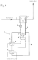
- a heat transport circuit 1 which has a circuit line 2 with a circulating pump 3 for the heat carrier circulating in the heat transport circuit 1.
- the heating path of a heat exchanger 4 is installed, the cooling path of which is built into the exhaust air line 5, so that the exhaust air is cooled and usable heat is recovered.
- a consumption heat exchanger 6 is also installed, which is assigned to a heat consumer, for example a pre-dryer for wood chips.
- the circuit line 2 is divided into a circuit line section 7 from the heat exchanger 4 to the heat consumer and into a circuit line section 8 from the heat consumer to the heat exchanger (4).
- a bypass line 9 branches off from the circuit line section 7 and opens into the circuit line section 8 bypassing the heat consumer or the consumption heat exchanger 6.
- a heat pump 10 is installed, which extracts heat from the heat carrier flowing through the bypass line 9, so that the cooling circuit exchanger of the heat pump 10 is formed by the heat exchanger 4.
- the heating circuit exchanger 11 of the heat pump 10 is installed in the circuit line section 7 behind the branch point of the bypass line 9 and thus brings about a reheating or an increase in temperature of the heat carrier flowing to the consumption heat exchanger 6.
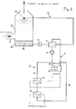
- the system according to FIG. 2 corresponds to the configuration according to FIG. 1 with regard to the heat transport circuit and the associated units, so that the same reference numerals are entered and no description is given again.
- This counterflow washer 12 is connected to the heat exchanger 4 by an intermediate circuit 13, whereby warm washing liquid 16 taken from the sump 15 of the counterflow washer 12 is passed through the cooling path of the heat exchanger 4 by means of a circulation pump 14 and is fed to the spray nozzles 17 of the counterflow washer 12.
- the countercurrent washer 12 is shown in simplified form without devices for metering in fresh washing liquid and the outflow of washing liquid diluted or used up by condensate and impurities.
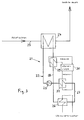
- the system according to FIG. 3 has aggregates and design features corresponding to the system according to FIG. 1, namely a heat transport circuit 21 with a circuit line 22 and a circulation pump 23, a heat exchanger 24, an exhaust air line 25, a consumption heat exchanger 26, circuit line sections 27 and 28 and a heat pump 30.
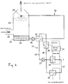
- the system according to FIG. 4 corresponds to the configuration according to FIG. 3 with regard to the heat transport circuit and the associated units, so that the same reference numerals are entered and no description is given again.
- the difference to the system in FIG. 3 is that the exhaust air line 25 does not lead through the heat exchanger 24 but is passed through a counterflow washer 32 and is cooled and washed in the process.
- This countercurrent washer 32 is connected to the heat exchanger 24 by an intermediate circuit 33, warm washing liquid 36 taken from the sump 35 of the countercurrent washer 32 being passed through the cooling path of the heat exchanger 24 by means of a circulation pump 34 and being fed to the spray nozzles 37 of the countercurrent washer 32.
- the countercurrent washer 32 is again shown in a simplified manner without devices for metering in fresh washing liquid and the outflow of washing liquid diluted or used up by condensate and impurities.
Applications Claiming Priority (2)
| Application Number | Priority Date | Filing Date | Title |
|---|---|---|---|
| DE4123556 | 1991-07-16 | ||
| DE4123556A DE4123556A1 (de) | 1991-07-16 | 1991-07-16 | Verfahren und vorrichtung zur rueckgewinnung von waerme aus trocknungs- oder abluftreinigungsanlagen |
Publications (1)
| Publication Number | Publication Date |
|---|---|
| EP0523684A1 true EP0523684A1 (fr) | 1993-01-20 |
Family
ID=6436274
Family Applications (1)
| Application Number | Title | Priority Date | Filing Date |
|---|---|---|---|
| EP92112128A Withdrawn EP0523684A1 (fr) | 1991-07-16 | 1992-07-16 | Procédé et dispositif pour la récupération de chaleur dans des installations de séchage ou de purification d'air d'échappement |
Country Status (2)
| Country | Link |
|---|---|
| EP (1) | EP0523684A1 (fr) |
| DE (1) | DE4123556A1 (fr) |
Cited By (10)
| Publication number | Priority date | Publication date | Assignee | Title |
|---|---|---|---|---|
| EP1816397A1 (fr) | 2006-02-02 | 2007-08-08 | Fritz Egger GmbH & Co | Procédé et dispositif destinés au gain de chaleur à partir d'air chargé en humidité |
| ITFI20110076A1 (it) * | 2011-04-19 | 2012-10-20 | Unitech Textile Machinery S P A | "macchina per il trattamento di tessuti con recupero di calore" |
| CN102997630A (zh) * | 2012-11-19 | 2013-03-27 | 王兆进 | 一种带气气换热器的红外烘干机 |
| CN104215058A (zh) * | 2013-05-30 | 2014-12-17 | 中国科学院工程热物理研究所 | 固体物料干燥装置 |
| CN106196986A (zh) * | 2016-08-02 | 2016-12-07 | 银永忠 | 热泵式热回收农作物高效干燥装置 |
| EP3184946A1 (fr) * | 2015-12-23 | 2017-06-28 | Essent Power B.V. | Dispositif pour sécher un matériau humide |
| WO2018206334A1 (fr) * | 2017-05-12 | 2018-11-15 | Siemens Aktiengesellschaft | Dispositif et procédé pour accroître le rendement thermique d'une source de chaleur |
| WO2018206335A1 (fr) * | 2017-05-12 | 2018-11-15 | Siemens Aktiengesellschaft | Dispositif et procédé pour accroître le rendement thermique d'une source de chaleur |
| DE102019116898A1 (de) * | 2019-06-24 | 2020-12-24 | Lasco Heutechnik Gmbh | Trocknungssystem und Trocknungsverfahren |
| WO2023036386A1 (fr) * | 2021-09-13 | 2023-03-16 | Lübbers Anlagen- und Umwelttechnik GmbH | Dispositif de séchage destiné à fournir un gaz de traitement pour une installation de séchage |
Families Citing this family (3)
| Publication number | Priority date | Publication date | Assignee | Title |
|---|---|---|---|---|
| NL2011617C2 (nl) * | 2013-10-15 | 2015-04-16 | Kea Consult B V | Systeem en werkwijze voor winning van warmte uit een gasstroom. |
| DE102019116899A1 (de) * | 2019-06-24 | 2020-12-24 | Lasco Heutechnik Gmbh | Trocknungsvorrichtung und -verfahren |
| CN110895096B (zh) * | 2019-12-13 | 2024-01-12 | 广州万二二麦工程技术有限公司 | 空气流量精准均匀调节的装置及烟叶高效除湿烘干装置 |
Citations (4)
| Publication number | Priority date | Publication date | Assignee | Title |
|---|---|---|---|---|
| DE2800238A1 (de) * | 1978-01-04 | 1979-07-05 | Fraunhofer Ges Forschung | Verfahren zur verringerung der brand- und explosionsgefahr beim trocknen korn-, span- oder faserfoermiger stoffe |
| GB2052704A (en) * | 1979-05-31 | 1981-01-28 | Gea Luftkuehler Happel Gmbh | Air Temperature Control Apparatus |
| EP0326818A1 (fr) * | 1988-02-03 | 1989-08-09 | Maschinenfabrik Gustav Eirich | Procédé pour extraire du liquide d'un matériau humide |
| EP0385372A1 (fr) * | 1989-02-27 | 1990-09-05 | FRITZ EGGER GESELLSCHAFT m.b.H. | Procédé et dispositif pour le séchage de copeaux de bois |
-
1991
- 1991-07-16 DE DE4123556A patent/DE4123556A1/de not_active Withdrawn
-
1992
- 1992-07-16 EP EP92112128A patent/EP0523684A1/fr not_active Withdrawn
Patent Citations (4)
| Publication number | Priority date | Publication date | Assignee | Title |
|---|---|---|---|---|
| DE2800238A1 (de) * | 1978-01-04 | 1979-07-05 | Fraunhofer Ges Forschung | Verfahren zur verringerung der brand- und explosionsgefahr beim trocknen korn-, span- oder faserfoermiger stoffe |
| GB2052704A (en) * | 1979-05-31 | 1981-01-28 | Gea Luftkuehler Happel Gmbh | Air Temperature Control Apparatus |
| EP0326818A1 (fr) * | 1988-02-03 | 1989-08-09 | Maschinenfabrik Gustav Eirich | Procédé pour extraire du liquide d'un matériau humide |
| EP0385372A1 (fr) * | 1989-02-27 | 1990-09-05 | FRITZ EGGER GESELLSCHAFT m.b.H. | Procédé et dispositif pour le séchage de copeaux de bois |
Cited By (16)
| Publication number | Priority date | Publication date | Assignee | Title |
|---|---|---|---|---|
| EP1816397A1 (fr) | 2006-02-02 | 2007-08-08 | Fritz Egger GmbH & Co | Procédé et dispositif destinés au gain de chaleur à partir d'air chargé en humidité |
| ITFI20110076A1 (it) * | 2011-04-19 | 2012-10-20 | Unitech Textile Machinery S P A | "macchina per il trattamento di tessuti con recupero di calore" |
| WO2012143292A1 (fr) * | 2011-04-19 | 2012-10-26 | Unitech Textile Machinery S.P.A. | Machine de traitement des textiles à récupération de chaleur |
| CN102997630A (zh) * | 2012-11-19 | 2013-03-27 | 王兆进 | 一种带气气换热器的红外烘干机 |
| CN104215058A (zh) * | 2013-05-30 | 2014-12-17 | 中国科学院工程热物理研究所 | 固体物料干燥装置 |
| CN104215058B (zh) * | 2013-05-30 | 2016-02-24 | 中国科学院工程热物理研究所 | 固体物料干燥装置 |
| EP3184946A1 (fr) * | 2015-12-23 | 2017-06-28 | Essent Power B.V. | Dispositif pour sécher un matériau humide |
| CN106196986B (zh) * | 2016-08-02 | 2018-09-14 | 山东圣克莱尔新能源有限公司 | 热泵式热回收农作物高效干燥装置 |
| CN106196986A (zh) * | 2016-08-02 | 2016-12-07 | 银永忠 | 热泵式热回收农作物高效干燥装置 |
| WO2018206334A1 (fr) * | 2017-05-12 | 2018-11-15 | Siemens Aktiengesellschaft | Dispositif et procédé pour accroître le rendement thermique d'une source de chaleur |
| WO2018206335A1 (fr) * | 2017-05-12 | 2018-11-15 | Siemens Aktiengesellschaft | Dispositif et procédé pour accroître le rendement thermique d'une source de chaleur |
| CN110621946A (zh) * | 2017-05-12 | 2019-12-27 | 西门子股份公司 | 用于提高热源的热功率的装置和方法 |
| US11300334B2 (en) | 2017-05-12 | 2022-04-12 | Siemens Energy Global GmbH & Co. KG | Device and method for increasing the thermal output of a heat source |
| DE102019116898A1 (de) * | 2019-06-24 | 2020-12-24 | Lasco Heutechnik Gmbh | Trocknungssystem und Trocknungsverfahren |
| EP3757494A1 (fr) * | 2019-06-24 | 2020-12-30 | LASCO Heutechnik GmbH | Système de séchage et procédé de séchage |
| WO2023036386A1 (fr) * | 2021-09-13 | 2023-03-16 | Lübbers Anlagen- und Umwelttechnik GmbH | Dispositif de séchage destiné à fournir un gaz de traitement pour une installation de séchage |
Also Published As
| Publication number | Publication date |
|---|---|
| DE4123556A1 (de) | 1993-01-21 |
Similar Documents
| Publication | Publication Date | Title |
|---|---|---|
| EP0526816B1 (fr) | Centrale à turbines à gaz et à vapeur avec un générateur de vapeur solaire | |
| EP0523684A1 (fr) | Procédé et dispositif pour la récupération de chaleur dans des installations de séchage ou de purification d'air d'échappement | |
| EP1023526B1 (fr) | Systeme de turbine a gaz et a vapeur et procede permettant de faire fonctionner un systeme de ce type | |
| CH627524A5 (de) | Verfahren und anlage zur waermenutzung durch waermeentzug aus mindestens einem stroemenden waermetraeger. | |
| WO1999010627A1 (fr) | Procede pour utiliser une installation de turbines a gaz et a vapeur et installation de turbines a gaz et a vapeur pour la mise en oeuvre du procede | |
| EP1602401B2 (fr) | Procédé et dispositif de condensation partielle contenant peu d'aerosols | |
| DE2311066A1 (de) | Dampferzeuger fuer ungefeuerte kraftanlage | |
| WO2000011325A1 (fr) | Installation de turbine a gaz et a vapeur | |
| DE2630853A1 (de) | Trocknungsvorrichtung | |
| DE3152374C2 (de) | Verfahren und Vorrichtung zur Rückgewinnung von Wärmeenergie aus mehreren Wärmeträgermedien einer wärmeverbrauchenden Anlage | |
| EP0203059B1 (fr) | Procédé de séchage d'une matière granuleuse et un séchoir à lit fluidisé | |
| EP1193373A1 (fr) | Méthode pour opérer une installation à turbines à gaz et à vapeur et installation correspondante | |
| EP0840837B1 (fr) | Procede d'exploitation d'une installation de turbines a gaz et a vapeur et installation exploitee selon ce procede | |
| DE3512463A1 (de) | Verfahren zur reduzierung des waermeverbrauchs an flaschenreinigungsmaschinen | |
| EP0406355A1 (fr) | Procede et dispositif pour recuperer la chaleur perdue contenue dans l'air de sechage humide sortant du seche-papier des machines a papier | |
| DE3644323A1 (de) | Verfahren und einrichtung zur thermischen behandlung einer kontinuierlich bewegten textilen warenbahn | |
| EP0476449B1 (fr) | Procédé et dispositif pour le séchage du gaz naturel et pour le recyclage du solvant de l'eau utilisé en cela | |
| DE3311505C2 (fr) | ||
| DE2207035B2 (de) | Verfahren und vorrichtung zur verbrennungslosen rueckgewinnung der expansionsenergie von hochofengas | |
| DE3316418C2 (de) | Regenerativwärmetauschersystem | |
| EP0019297A2 (fr) | Méthode et dispositif pour produire de la vapeur | |
| DE19825597A1 (de) | Verfahren sowie Anlage zum Trocknen von Feuchtgut | |
| WO2004062761A2 (fr) | Procede pour purifier le gaz de processus d'un four a braser, four a braser et systeme de purification pour la mise en oeuvre dudit procede | |
| EP0618404B1 (fr) | Procédé et installation pour la génération de vapeur dans une centrale de puissance et de chaleur | |
| DE3635707C2 (fr) |
Legal Events
| Date | Code | Title | Description |
|---|---|---|---|
| PUAI | Public reference made under article 153(3) epc to a published international application that has entered the european phase |
Free format text: ORIGINAL CODE: 0009012 |
|
| AK | Designated contracting states |
Kind code of ref document: A1 Designated state(s): AT CH DE FR IT LI |
|
| 17P | Request for examination filed |
Effective date: 19930720 |
|
| 17Q | First examination report despatched |
Effective date: 19940426 |
|
| STAA | Information on the status of an ep patent application or granted ep patent |
Free format text: STATUS: THE APPLICATION IS DEEMED TO BE WITHDRAWN |
|
| 18D | Application deemed to be withdrawn |
Effective date: 19940907 |