EP0523684A1 - Process and apparatus for heat recovery from drying plants or waste air purification plants - Google Patents
Process and apparatus for heat recovery from drying plants or waste air purification plants Download PDFInfo
- Publication number
- EP0523684A1 EP0523684A1 EP92112128A EP92112128A EP0523684A1 EP 0523684 A1 EP0523684 A1 EP 0523684A1 EP 92112128 A EP92112128 A EP 92112128A EP 92112128 A EP92112128 A EP 92112128A EP 0523684 A1 EP0523684 A1 EP 0523684A1
- Authority
- EP
- European Patent Office
- Prior art keywords
- heat
- circuit
- exchanger
- exhaust air
- consumer
- Prior art date
- Legal status (The legal status is an assumption and is not a legal conclusion. Google has not performed a legal analysis and makes no representation as to the accuracy of the status listed.)
- Withdrawn
Links
Images
Classifications
-
- F—MECHANICAL ENGINEERING; LIGHTING; HEATING; WEAPONS; BLASTING
- F26—DRYING
- F26B—DRYING SOLID MATERIALS OR OBJECTS BY REMOVING LIQUID THEREFROM
- F26B23/00—Heating arrangements
- F26B23/001—Heating arrangements using waste heat
- F26B23/002—Heating arrangements using waste heat recovered from dryer exhaust gases
- F26B23/005—Heating arrangements using waste heat recovered from dryer exhaust gases using a closed cycle heat pump system ; using a heat pipe system
-
- Y—GENERAL TAGGING OF NEW TECHNOLOGICAL DEVELOPMENTS; GENERAL TAGGING OF CROSS-SECTIONAL TECHNOLOGIES SPANNING OVER SEVERAL SECTIONS OF THE IPC; TECHNICAL SUBJECTS COVERED BY FORMER USPC CROSS-REFERENCE ART COLLECTIONS [XRACs] AND DIGESTS
- Y02—TECHNOLOGIES OR APPLICATIONS FOR MITIGATION OR ADAPTATION AGAINST CLIMATE CHANGE
- Y02B—CLIMATE CHANGE MITIGATION TECHNOLOGIES RELATED TO BUILDINGS, e.g. HOUSING, HOUSE APPLIANCES OR RELATED END-USER APPLICATIONS
- Y02B30/00—Energy efficient heating, ventilation or air conditioning [HVAC]
- Y02B30/52—Heat recovery pumps, i.e. heat pump based systems or units able to transfer the thermal energy from one area of the premises or part of the facilities to a different one, improving the overall efficiency
-
- Y—GENERAL TAGGING OF NEW TECHNOLOGICAL DEVELOPMENTS; GENERAL TAGGING OF CROSS-SECTIONAL TECHNOLOGIES SPANNING OVER SEVERAL SECTIONS OF THE IPC; TECHNICAL SUBJECTS COVERED BY FORMER USPC CROSS-REFERENCE ART COLLECTIONS [XRACs] AND DIGESTS
- Y02—TECHNOLOGIES OR APPLICATIONS FOR MITIGATION OR ADAPTATION AGAINST CLIMATE CHANGE
- Y02P—CLIMATE CHANGE MITIGATION TECHNOLOGIES IN THE PRODUCTION OR PROCESSING OF GOODS
- Y02P70/00—Climate change mitigation technologies in the production process for final industrial or consumer products
- Y02P70/10—Greenhouse gas [GHG] capture, material saving, heat recovery or other energy efficient measures, e.g. motor control, characterised by manufacturing processes, e.g. for rolling metal or metal working
Definitions
- the invention relates to a method for recovering heat, in particular condensation heat, from exhaust air loaded with water vapor from drying or exhaust air purification systems, in which the exhaust air is passed and cooled by a heat exchanger, through which a heat transfer medium is circulated in a heat transport circuit and thereby heat from Heat exchanger is transported to a heat consumer.
- Such a method is known from EP-A 385 372. It is a system for drying wood chips or wood fibers, in which the exhaust air separated from the dried chips in a cyclone separator, which contains the combustion gases that are passed through direct contact with the material through the dryer and are loaded with water vapor and wood impurities, is washed in a countercurrent scrubber becomes.
- the washing liquid is circulated from the scrubber sump to the scrubber nozzles by an intermediate circuit, a heat exchanger coupling this intermediate circuit to a heat transport circuit which supplies the recovered heat or thermal energy to a consumer, who is preferably a pre-dryer for the wood chips.
- the waste heat can also be used, for example, to heat air that is mixed with the washed exhaust air or used as combustion air.
- heat pumps are suitable for bringing thermal energy from a low temperature level to a higher temperature level.
- the coefficient of performance of the heat pump is of crucial importance for the economy of such a measure. This designates the ratio of the drive energy required by the heat pump to the amount of heat emitted by the heat pump.
- the coefficient of performance is influenced by the temperature spread between the heating circuit and the cooling circuit of the heat pump, a larger temperature spread being associated with a lower coefficient of performance. It should be taken into account that with a larger output of the heat pump, its space requirements and the acquisition and operating costs increase.
- the development of high-temperature heat pumps with heating circuit temperatures up to over 100 o C is still in progress, whereby heat pumps operating according to different principles can be used according to the respective initial conditions of waste heat utilization.
- the invention has for its object to improve the economy of the previous heat recovery and thereby reduce the environmental impact.
- This object is achieved in that the temperature of the heat transfer medium behind the heat exchanger and in front of the heat consumer is increased by means of at least one heat pump with which a quantity of heat extracted from the exhaust air is transmitted which is smaller than the quantity of heat supplied to the heat consumer.
- the heat recovery according to the invention is therefore based on a combination of (at least) one heat exchanger and (at least) one heat pump, in which the heat exchanger absorbs all of the recovered heat, but the heat pump absorbs only a part of the waste heat, so that the heat energy supplied to the consumer is increased Reheat temperature level.
- the heat energy absorbed by the cooling circuit of the heat pump expediently comes from the heat transport circuit, for example from the heat carrier of the heat transport circuit flowing back from the heat consumer to the heat exchanger, or from a partial flow of the heat transport circuit which bypasses the consumer.
- the heat pump serving only for reheating a heat flow bypassing the heat pump to the consumer can be designed to be comparatively small and operated economically, with the consumer still being provided with waste heat at a comparatively high temperature level. Because of these circumstances, the use of waste heat is also interesting in those cases in which heat recovery has so far been avoided for economic reasons.
- Another advantage of the invention is that even if the heat pump fails completely or if it is serviced or repaired, the waste heat can be used, albeit to a limited extent Dimensions. Furthermore, the use of the heat pump leads to increased cooling of the heat carrier flowing back to the heat exchanger, which increases the temperature difference in the heat exchanger and thus leads to an increase in heat recovery. With the stronger cooling of the exhaust air, the condensation of pollutants from the exhaust air increases, which ultimately reduces emissions.
- the combination of steam jet heat pumps with absorption-compressor heat pumps can be particularly advantageous when heat transfer temperatures in the range of 100 o C and above are required or when two or more heat transport circuits with different temperatures are to be fed.
- the respective site conditions must be taken into account, which also includes the space available, the technical training of the operating personnel, the energy costs, the service life, the heat supply and the use potential for the waste heat.
- the advantages of the method according to the invention can be further increased by adapting the output of the heat pump and / or the temperature increase brought about by the heat pump in the heat transport circuit to these fluctuating operating conditions.
- a control task can be solved particularly advantageously by using several heat pumps, it often being sufficient if only one of the heat pumps is operated in a controlled manner.
- other options are feasible to achieve optimal heat recovery taking into account technical and / or economic considerations when several heat consumers are supplied with different heat supply in the exhaust air flow or different heat requirements in the heat consumers.
- the invention also relates to a device used to carry out the aforementioned method with a heat transport circuit line, a circulation pump built into the circuit line, a heat exchanger, the cooling path of which is provided for cooling the exhaust air and the heating path of which is arranged in the circuit line, and one connected to the circuit line Heat consumer.
- a device used to carry out the aforementioned method with a heat transport circuit line, a circulation pump built into the circuit line, a heat exchanger, the cooling path of which is provided for cooling the exhaust air and the heating path of which is arranged in the circuit line, and one connected to the circuit line Heat consumer.
- a device is also known from EP-A 385 372.
- this device is characterized in that at least one heat pump is assigned to the circuit line is whose heating circuit exchanger is installed in the circuit line section from the heat exchanger to the heat consumer and whose cooling circuit exchanger is installed in a line section transporting exhaust air heat.
- the device is suitable for carrying out the method according to the invention and thus for achieving the advantages described above.
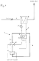
- a heat transport circuit 1 which has a circuit line 2 with a circulating pump 3 for the heat carrier circulating in the heat transport circuit 1.
- the heating path of a heat exchanger 4 is installed, the cooling path of which is built into the exhaust air line 5, so that the exhaust air is cooled and usable heat is recovered.
- a consumption heat exchanger 6 is also installed, which is assigned to a heat consumer, for example a pre-dryer for wood chips.
- the circuit line 2 is divided into a circuit line section 7 from the heat exchanger 4 to the heat consumer and into a circuit line section 8 from the heat consumer to the heat exchanger (4).
- a bypass line 9 branches off from the circuit line section 7 and opens into the circuit line section 8 bypassing the heat consumer or the consumption heat exchanger 6.
- a heat pump 10 is installed, which extracts heat from the heat carrier flowing through the bypass line 9, so that the cooling circuit exchanger of the heat pump 10 is formed by the heat exchanger 4.
- the heating circuit exchanger 11 of the heat pump 10 is installed in the circuit line section 7 behind the branch point of the bypass line 9 and thus brings about a reheating or an increase in temperature of the heat carrier flowing to the consumption heat exchanger 6.
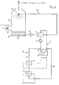
- the system according to FIG. 2 corresponds to the configuration according to FIG. 1 with regard to the heat transport circuit and the associated units, so that the same reference numerals are entered and no description is given again.
- This counterflow washer 12 is connected to the heat exchanger 4 by an intermediate circuit 13, whereby warm washing liquid 16 taken from the sump 15 of the counterflow washer 12 is passed through the cooling path of the heat exchanger 4 by means of a circulation pump 14 and is fed to the spray nozzles 17 of the counterflow washer 12.
- the countercurrent washer 12 is shown in simplified form without devices for metering in fresh washing liquid and the outflow of washing liquid diluted or used up by condensate and impurities.
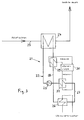
- the system according to FIG. 3 has aggregates and design features corresponding to the system according to FIG. 1, namely a heat transport circuit 21 with a circuit line 22 and a circulation pump 23, a heat exchanger 24, an exhaust air line 25, a consumption heat exchanger 26, circuit line sections 27 and 28 and a heat pump 30.
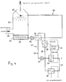
- the system according to FIG. 4 corresponds to the configuration according to FIG. 3 with regard to the heat transport circuit and the associated units, so that the same reference numerals are entered and no description is given again.
- the difference to the system in FIG. 3 is that the exhaust air line 25 does not lead through the heat exchanger 24 but is passed through a counterflow washer 32 and is cooled and washed in the process.
- This countercurrent washer 32 is connected to the heat exchanger 24 by an intermediate circuit 33, warm washing liquid 36 taken from the sump 35 of the countercurrent washer 32 being passed through the cooling path of the heat exchanger 24 by means of a circulation pump 34 and being fed to the spray nozzles 37 of the countercurrent washer 32.
- the countercurrent washer 32 is again shown in a simplified manner without devices for metering in fresh washing liquid and the outflow of washing liquid diluted or used up by condensate and impurities.
Abstract
Description
Die Erfindung bezieht sich auf ein Verfahren zur Rückgewinnung von Wärme, insbesondere Kondensationswärme, aus mit Wasserdampf beladener Abluft aus Trocknungs- oder Abluftreinigungsanlagen, bei dem die Abluft durch einen Wärmetauscher geleitet und gekühlt wird, durch den in einem Wärmetransportkreis ein Wärmeträger umgewälzt und dadurch Wärme vom Wärmetauscher zu einem Wärmeverbraucher transportiert wird.The invention relates to a method for recovering heat, in particular condensation heat, from exhaust air loaded with water vapor from drying or exhaust air purification systems, in which the exhaust air is passed and cooled by a heat exchanger, through which a heat transfer medium is circulated in a heat transport circuit and thereby heat from Heat exchanger is transported to a heat consumer.
Ein solches Verfahren ist aus der EP-A 385 372 bekannt. Dort handelt es sich um eine Anlage zum Trocknen von Holzspänen oder Holzfasern, bei dem die in einem Zyklonabscheider von den getrockneten Spänen getrennte Abluft, welche die in direktem Materialkontakt durch den Trockner geleiteten und dort mit Wasserdampf und Holzverunreinigungen beladenen Verbrennungsgase enthält, in einem Gegenstromwäscher gewaschen wird. Die Waschflüssigkeit wird durch einen Zwischenkreis vom Wäschersumpf zu den Wäscherdüsen umgewälzt, wobei ein Wärmetauscher diesen Zwischenkreis mit einem Wärmetransportkreis koppelt, der die rückgewonnene Wärme bzw. Wärmeenergie einem Verbraucher zuführt, bei dem es sich bevorzugt um einen Vortrockner für die Holzspäne handelt. Mit der Abwärme kann aber beispielsweise auch Luft erhitzt werden, die der gewaschenen Abluft beigemischt oder als Verbrennungsluft eingesetzt wird.Such a method is known from EP-A 385 372. It is a system for drying wood chips or wood fibers, in which the exhaust air separated from the dried chips in a cyclone separator, which contains the combustion gases that are passed through direct contact with the material through the dryer and are loaded with water vapor and wood impurities, is washed in a countercurrent scrubber becomes. The washing liquid is circulated from the scrubber sump to the scrubber nozzles by an intermediate circuit, a heat exchanger coupling this intermediate circuit to a heat transport circuit which supplies the recovered heat or thermal energy to a consumer, who is preferably a pre-dryer for the wood chips. The waste heat can also be used, for example, to heat air that is mixed with the washed exhaust air or used as combustion air.
Bei einem solchen Holzspänetrockner werden große Wassermengen verdampft. Damit steckt in der Abluft ein großes Energiepotential, dessen Rückgewinnung bzw. Nutzung jedoch dadurch eingeschränkt wird, daß die Wärme in einem vergleichsweise niedrigen Temperaturbereich anfällt. Die mit Wasserdampf beladene Abluft des Holzspänetrockners weist beispielsweise Taupunkttemperaturen im Bereich von ca. 65 bis 70o c auf. Bei diesem niedrigen Temperaturniveau ist die Abwärmenutzung mit einem verhältnismäßig hohen apparativen Aufwand (große Wärmetauscher) und einem entsprechenden Platzbedarf verbunden. Daher ist eine Erhöhung des Temperaturniveaus der anfallenden Abwärme häufig eine Vorbedingung für die Wirtschaftlichkeit der Wärmerückgewinnung. Das gilt nicht nur für die Wärmerückgewinnung bei Trocknungsanlagen für Holzspäne sondern allgemein für die Rückgewinnung von Abluftwärme sowie für fast alle Arten der Abwärmenutzung, so beispielsweise auch für die Einspeisung von Abwärme in Fernwärmenetze.With such a wood chip dryer, large amounts of water are evaporated. This means that there is great energy potential in the exhaust air, the recovery or use of which is restricted by the fact that the heat is generated in a comparatively low temperature range. The waste air loaded with water vapor from the wood chip dryer has, for example, dew point temperatures in the range from approx. 65 to 70 o c. At this low temperature level, the use of waste heat is associated with a relatively high expenditure on equipment (large heat exchangers) and a corresponding space requirement. Therefore, an increase in the temperature level of the waste heat is often a prerequisite for the economy of heat recovery. This applies not only to the heat recovery in drying plants for wood chips, but generally to the recovery of exhaust air heat as well as to almost all types of waste heat utilization, for example also for the feeding of waste heat into district heating networks.
Bekanntlich eignen sich Wärmepumpen dafür, Wärmeenergie von niedrigem Temperaturniveau auf ein höheres Temperaturniveau zu bringen. Für die Wirtschaftlichkeit einer solchen Maßnahme ist die Leistungszahl der Wärmepumpe von maßgeblicher Bedeutung. Diese bezeichnet das Verhältnis der von der Wärmepumpe benötigten Antriebsenergie zu der von der Wärmepumpe abgegebenen Wärmemenge. Die Leistungszahl wird von der Temperaturspreizung zwischen dem Heizkreis und dem Kühlkreis der Wärmepumpe beeinflußt, wobei eine größere Temperaturspreizung mit einer geringeren Leistungszahl verbunden ist. Zu berücksichtigen ist, daß mit einer größeren Leistung der Wärmepumpe ihr Platzbedarf sowie die Anschaffungs- und Betriebskosten ansteigen. Die Entwicklung von Hochtemperatur-Wärmepumpen mit Heizkreistemperaturen bis über 100o C ist noch im Gange, wobei nach verschiedenen Prinzipien arbeitende Wärmepumpen nach den jeweiligen Ausgangsbedingungen der Abwärmenutzung eingesetzt werden können.As is known, heat pumps are suitable for bringing thermal energy from a low temperature level to a higher temperature level. The coefficient of performance of the heat pump is of crucial importance for the economy of such a measure. This designates the ratio of the drive energy required by the heat pump to the amount of heat emitted by the heat pump. The coefficient of performance is influenced by the temperature spread between the heating circuit and the cooling circuit of the heat pump, a larger temperature spread being associated with a lower coefficient of performance. It should be taken into account that with a larger output of the heat pump, its space requirements and the acquisition and operating costs increase. The development of high-temperature heat pumps with heating circuit temperatures up to over 100 o C is still in progress, whereby heat pumps operating according to different principles can be used according to the respective initial conditions of waste heat utilization.
Es ist bereits bekannt, bei einer Holzspantrocknungsanlage mit im Gegenstrom gewaschener Abluft eine Wärmepumpe einzusetzen, die der umgewälzten Waschflüssigkeit Wärmeenergie entzieht und auf ein höheres Temperaturniveau bringt, um vom gewaschenen Abgas abgezweigtes Rückgas zu erwärmen, das zur Brennkammer zurückströmt (DE-OS 28 00 238). Hierbei wird der umgewälzten Waschflüssigkeit Wärme nur durch den Kühlkreistauscher der Wärmepumpe entzogen, wobei die gesamte genutzte Abwärme durch die Wärmepumpe übertragen wird, deren Heizkreistauscher vom zu erwärmenden Rückgas durchströmt wird. Die Belastung der Wärmepumpe mit der gesamten zu nutzenden Abwärme führt dazu, daß die Wärmepumpe vergleichsweise groß ausgelegt werden muß und nicht mit der gewünschten hohen Wirtschaftlichkeit arbeitet.It is already known to use a heat pump in a wood-chip drying system with exhaust air washed in countercurrent, which extracts thermal energy from the circulated washing liquid and brings it to a higher temperature level in order to heat back gas branched off from the washed exhaust gas, which flows back to the combustion chamber (DE-OS 28 00 238 ). In this case, the circulated washing liquid receives heat only through the cooling circuit exchanger of the heat pump withdrawn, the total waste heat used is transferred by the heat pump, the heating circuit exchanger is flowed through by the return gas to be heated. The load on the heat pump with the total waste heat to be used means that the heat pump must be designed to be comparatively large and does not work with the desired high level of economy.
Der Erfindung liegt die Aufgabe zugrunde, die Wirtschaftlichkeit der bisherigen Wärmerückgewinnung zu verbessern und dadurch die Umweltbelastung zu senken.The invention has for its object to improve the economy of the previous heat recovery and thereby reduce the environmental impact.
Diese Aufgabe wird erfindungsgemäß dadurch gelöst, daß die Temperatur des Wärmeträgers hinter dem Wärmetauscher und vor dem Wärmeverbraucher mittels wenigstens einer Wärmepumpe erhöht wird, mit der eine der Abluft entzogene Wärmemenge übertragen wird, die kleiner als die dem Wärmeverbraucher zugeführte Wärmemenge ist.This object is achieved in that the temperature of the heat transfer medium behind the heat exchanger and in front of the heat consumer is increased by means of at least one heat pump with which a quantity of heat extracted from the exhaust air is transmitted which is smaller than the quantity of heat supplied to the heat consumer.
Die erfindungsgemäße Wärmerückgewinnung basiert also auf einer Kombination (wenigstens) eines Wärmetauschers und (wenigstens) einer Wärmepumpe, bei der der Wärmetauscher die gesamte rückgewonnene Wärme aufnimmt, die Wärmepumpe aber nur einen Teil der Abwärme aufnimmt, um damit die dem Verbraucher zugeführte Wärmeenergie auf ein erhöhtes Temperaturniveau nachzuerwärmen. Dabei stammt die vom Kühlkreis der Wärmepumpe aufgenommene Wärmeenergie zweckmäßigerweise aus dem Wärmetransportkreis, beispielsweise aus dem vom Wärmeverbraucher zum Wärmetauscher zurückströmenden Wärmeträger des Wärmetransportkreises oder aus einem den Verbraucher umgehenden Teilstrom des Wärmetransportkreises. In beiden Fällen kann die lediglich zur Nacherwärmung eines die Wärmepumpe umgehenden Wärmestroms zum Verbraucher dienende Wärmepumpe vergleichsweise klein ausgelegt und wirtschaftlich betrieben werden, wobei trotzdem dem Verbraucher Abwärme auf einem vergleichsweise hohen Temperaturniveau zur Verfügung gestellt wird. Auf Grund dieser Gegebenheiten wird die Abwärmenutzung auch in solchen Fällen interessant, in denen bisher aus wirtschaftlichen Erwägungen auf eine Wärmerückgewinnung verzichtet wurde.The heat recovery according to the invention is therefore based on a combination of (at least) one heat exchanger and (at least) one heat pump, in which the heat exchanger absorbs all of the recovered heat, but the heat pump absorbs only a part of the waste heat, so that the heat energy supplied to the consumer is increased Reheat temperature level. The heat energy absorbed by the cooling circuit of the heat pump expediently comes from the heat transport circuit, for example from the heat carrier of the heat transport circuit flowing back from the heat consumer to the heat exchanger, or from a partial flow of the heat transport circuit which bypasses the consumer. In both cases, the heat pump serving only for reheating a heat flow bypassing the heat pump to the consumer can be designed to be comparatively small and operated economically, with the consumer still being provided with waste heat at a comparatively high temperature level. Because of these circumstances, the use of waste heat is also interesting in those cases in which heat recovery has so far been avoided for economic reasons.
Ein weiterer Vorteil der Erfindung liegt darin, daß selbst bei vollständigem Ausfall der Wärmepumpe bzw. ihrer Wartung oder Reparatur die Abwärme genutzt werden kann, wenn auch in eingeschränktem Maße. Ferner führt die Anwendung der Wärmepumpe zu einer erhöhten Abkühlung des zum Wärmetauscher zurückströmenden Wärmeträgers, was die Temperaturdifferenz im Wärmetauscher erhöht und damit zu einer Steigerung der Wärmerückgewinnung führt. Mit der stärkeren Abkühlung der Abluft verstärkt sich zugleich die Kondensation von Schadstoffen aus der Abluft, wodurch letztlich die Emmissionen herabgesetzt werden.Another advantage of the invention is that even if the heat pump fails completely or if it is serviced or repaired, the waste heat can be used, albeit to a limited extent Dimensions. Furthermore, the use of the heat pump leads to increased cooling of the heat carrier flowing back to the heat exchanger, which increases the temperature difference in the heat exchanger and thus leads to an increase in heat recovery. With the stronger cooling of the exhaust air, the condensation of pollutants from the exhaust air increases, which ultimately reduces emissions.
Für den Fachmann ist leicht zu erkennen, daß es vorteilhaft sein kann, wenn für den Wärmeentzug mehrere Wärmetauscher eingesetzt werden, die parallel und/oder hintereinander geschaltet sind. Dies gilt insbesondere dann, wenn mehrere Abwärmequellen genutzt werden. Ebenso kann es sinnvoll sein, mehrere parallel und/oder hintereinander geschaltete Wärmepumpen einzusetzen. Dies kann vorteilhaft sein bei Berücksichtigung der auf dem Markt angebotenen Wärmepumpen mit unterschiedlichen Leistungen, aber auch aus Gründen der Betriebssicherheit oder zur besseren Anpassung an ein unterschiedliches Angebot von Abwärme bzw. an einen unterschiedlichen Wärmeverbraucherbedarf. Insbesondere kann auch die Verwendung von nach verschiedenen Prizipien arbeitenden Wärmepumpen sinnvoll sein, um unter Ausnutzung der besonderen Merkmale der jeweiligen Wärmepumpe eine bestmögliche Wirtschaftlichkeit zu erreichen. So kann die Kombination von Dampfstrahlwärmepumpen mit Absorptions-Kompressorwärmepumpen dann besonders vorteilhaft sein, wenn Wärmeträgertemperaturen im Bereich von 100o C und darüber erforderlich sind oder wenn zwei oder mehr Wärmetransportkreise mit unterschiedlichen Temperaturen angespeist werden sollen. Bei derartigen Konzepten sind die jeweiligen Standortbedingungen zu berücksichtigen, wozu auch das Platzangebot, die technische Schulung des Bedienungspersonals, die Energiekosten, die Nutzungsdauer, das Wärmeangebot und das Nutzungspotential für die Abwärme gehören.It is easy to recognize for the person skilled in the art that it can be advantageous if several heat exchangers are used for the heat removal, which are connected in parallel and / or in series. This is especially true when multiple waste heat sources are used. It can also make sense to use several heat pumps connected in parallel and / or in series. This can be advantageous when taking into account the heat pumps on the market with different outputs, but also for reasons of operational safety or for better adaptation to a different range of waste heat or to a different heat consumer requirement. In particular, the use of heat pumps operating according to different principles can also be useful in order to achieve the best possible economy using the special features of the respective heat pump. The combination of steam jet heat pumps with absorption-compressor heat pumps can be particularly advantageous when heat transfer temperatures in the range of 100 o C and above are required or when two or more heat transport circuits with different temperatures are to be fed. With such concepts, the respective site conditions must be taken into account, which also includes the space available, the technical training of the operating personnel, the energy costs, the service life, the heat supply and the use potential for the waste heat.
Versuche haben Berechnungen bestätigt, nach denen durch die erfindungsgemäße Kombination von Wärmetauschern und Wärmepumpen zur Rückgewinnung von Abwärme, die zum Vortrocknen genutzt wird, der Energieeinsatz für die Trocknung von Holzspänen um über 30 % reduziert werden kann, wobei sich gleichzeitig eine deutliche Herabsetzung der durch den Trocknungsvorgang hervorgerufenen Emissionen ergibt. Dabei wurde eine Temperaturerhöhung des Wärmeträgers im Wärmetransportkreis erzielt, die auch eine anderweitige Nutzung der Abwärme wirtschaftlich interessant erscheinen läßt, beispielsweise für eine Hallenheizung oder für die Einleitung in Fernwärmenetze.Experiments have confirmed calculations, according to which the combination of heat exchangers and heat pumps according to the invention for the recovery of waste heat, which is used for pre-drying, can reduce the energy input for drying wood chips by over 30%, while at the same time significantly reducing the throughput Drying process results in emissions. A temperature increase of the heat transfer medium in the heat transport circuit was achieved, which also makes it economically interesting to use the waste heat for other purposes can appear, for example for a hall heating or for the introduction into district heating networks.
In der Praxis ist es meist so, daß das Wärmeangebot des Abluftstroms nicht konstant ist, sondern Schwankungen aufweist. Ebenfalls wird die Abwärmenutzung häufig Schwankungen aufweisen, das heißt, daß der Wärmeentzug durch den Wärmeverbraucher aus dem Wärmetransportkreis variabel ist. Ferner kann es notwendig sein, daß die Temperatur des abströmenden Abluftstroms auf einem bestimmten Wert oder in einem bestimmten Bereich gehalten wird, z.B. erforderlich für eine nachfolgende Abluftbehandlung oder für die Sicherung eines thermischen Auftriebs, in letzterem Falle evtl. sogar mit einer der Außenlufttemperatur nachgeführten Mindestaustrittstemperatur des aus einem Kamin austretenden Abluftstroms.In practice, it is usually the case that the heat available in the exhaust air flow is not constant, but fluctuates. Waste heat utilization will also frequently fluctuate, which means that the heat removal by the heat consumer from the heat transport circuit is variable. Furthermore, it may be necessary to keep the temperature of the exhaust air stream flowing at a certain value or in a certain range, e.g. Required for a subsequent exhaust air treatment or for securing a thermal buoyancy, in the latter case possibly even with a minimum outlet temperature of the exhaust air stream emerging from a chimney that follows the outside air temperature.
In all diesen Fällen können die Vorteile des erfindungsgemäßen Verfahrens dadurch weiter gesteigert werden, daß die Leistung der Wärmepumpe und/oder die von der Wärmepumpe im Wärmetransportkreis bewirkte Temperaturerhöhung diesen schwankenden Betriebsbedingungen angepaßt wird. Bei mehreren Wärmeverbrauchern mit unterschiedlichem Wärmebedarf kann eine solche Regelaufgabe besonders vorteilhaft durch den Einsatz mehrerer Wärmepumpen gelöst werden, wobei es häufig genügt, wenn nur eine der Wärmepumpen geregelt betrieben wird. Daneben sind andere Möglichkeiten realisierbar, um bei einer Versorgung von mehreren Wärmeverbrauchern bei unterschiedlichem Wärmeangebot im Abluftstrom oder unterschiedlichem Wärmebedarf in den Wärmeverbrauchern eine unter Berücksichtigung technischer und/oder wirtschaftlicher Gesichtspunkte optimale Wärmerückgewinnung zu erreichen.In all these cases, the advantages of the method according to the invention can be further increased by adapting the output of the heat pump and / or the temperature increase brought about by the heat pump in the heat transport circuit to these fluctuating operating conditions. In the case of several heat consumers with different heat requirements, such a control task can be solved particularly advantageously by using several heat pumps, it often being sufficient if only one of the heat pumps is operated in a controlled manner. In addition, other options are feasible to achieve optimal heat recovery taking into account technical and / or economic considerations when several heat consumers are supplied with different heat supply in the exhaust air flow or different heat requirements in the heat consumers.
Die Erfindung bezieht sich auch auf eine der Durchführung des vorgenannten Verfahrens dienende Vorrichtung mit einer Wärmetransportkreislaufleitung, einer in die Kreislaufleitung eingebauten Umwälzpumpe, einem Wärmetauscher, dessen Kühlpfad zur Kühlung der Abluft vorgesehen und dessen Heizpfad in der Kreislaufleitung angeordnet ist, und einem an die Kreislaufleitung angeschlossenem Wärmeverbraucher. Eine derartige Vorrichtung ist ebenfalls aus der EP-A 385 372 bekannt.The invention also relates to a device used to carry out the aforementioned method with a heat transport circuit line, a circulation pump built into the circuit line, a heat exchanger, the cooling path of which is provided for cooling the exhaust air and the heating path of which is arranged in the circuit line, and one connected to the circuit line Heat consumer. Such a device is also known from EP-A 385 372.
Diese Vorrichtung ist erfindungsgemäß dadurch gekennzeichnet, daß der Kreislaufleitung wenigstens eine Wärmepumpe zugeordnet ist, deren Heizkreistauscher in den Kreislaufleitungsabschnitt vom Wärmetauscher zum Wärmeverbraucher und deren Kühlkreistauscher in einen Abluftwärme transportierenden Leitungsabschnitt eingebaut ist. Auf Grund dieser Ausbildung eignet sich die Vorrichtung für die Durchführung des erfindungsgemäßen Verfahrens und damit zur Erzielung der vorstehend beschriebenen Vorteile.According to the invention, this device is characterized in that at least one heat pump is assigned to the circuit line is whose heating circuit exchanger is installed in the circuit line section from the heat exchanger to the heat consumer and whose cooling circuit exchanger is installed in a line section transporting exhaust air heat. On the basis of this design, the device is suitable for carrying out the method according to the invention and thus for achieving the advantages described above.
Zweckmäßige Ausgestaltungen sowohl des Verfahrens wie der Vorrichtung nach der Erfindung ergeben sich aus den Unteransprüchen.Appropriate configurations of both the method and the device according to the invention result from the subclaims.
Mehrere Ausführungsbeispiele der Erfindung werden nachfolgend anhand von schematischen Zeichnungen näher erläutert. Es zeigen:
- Fig. 1
- einen Wärmetransportkreis mit einem von der Abluft durchströmten Wärmetauscher und einer Wärmepumpe, die einem den Wärmeverbraucher umgehenden Teilstrom des Wärmetransportkreises Wärme entzieht;
- Fig. 2
- einen
Figur 1 entsprechenden Wärmetransportkreis, wobei jedoch der Wärmetauscher über einen Zwischenkreis mit einem Gegenstromwäscher die Abluft kühlt; - Fig. 3
- einen Wärmetransportkreis mit einem von der Abluft durchströmten Wärmetauscher und einer Wärmepumpe, die dem vom Wärmeverbraucher zum Wärmetauscher zurückströmenden Wärmeträger im Wärmetransportkreis Wärme entzieht; und
- Fig. 4
- einen der
Figur 3 entsprechenden Wärmetransportkreis, bei dem jedoch der Wärmetauscher über einen Zwischenkreis mit einem Gegenstromwäscher die Abluft kühlt.
- Fig. 1
- a heat transport circuit with a heat exchanger through which the exhaust air flows and a heat pump which extracts heat from a partial flow of the heat transport circuit which bypasses the heat consumer;
- Fig. 2
- a heat transfer circuit corresponding to Figure 1, but the heat exchanger cools the exhaust air via an intermediate circuit with a counterflow washer;
- Fig. 3
- a heat transfer circuit with a heat exchanger through which the exhaust air flows and a heat pump which extracts heat from the heat carrier flowing back from the heat consumer to the heat exchanger in the heat transfer circuit; and
- Fig. 4
- a heat transfer circuit corresponding to FIG. 3, in which, however, the heat exchanger cools the exhaust air via an intermediate circuit with a counterflow washer.
Gemäß Figur 1 ist ein Wärmetransportkreis 1 vorgesehen, der eine Kreislaufleitung 2 mit einer Umwälzpumpe 3 für den im Wärmetransportkreis 1 zirkulierenden Wärmeträger aufweist. In den Wärmetransportkreis 1 ist der Heizpfad eines Wärmetauschers 4 eingebaut, dessen Kühlpfad in die Abluftleitung 5 eingebaut ist, so daß die Abluft gekühlt und dabei nutzbare Wärme zurückgewonnen wird.According to FIG. 1, a
In den Wärmetransportkreis 1 ist ferner ein Verbrauchswärmetauscher 6 eingebaut, der einem Wärmeverbraucher zugeordnet ist, beispielsweise einem Vortrockner für Holzspäne. Auf diese Weise ist die Kreislaufleitung 2 in einen Kreislaufleitungsabschnitt 7 vom Wärmetauscher 4 zum Wärmeverbraucher und in einen Kreislaufleitungsabschnitt 8 vom Wärmeverbraucher zum Wärmetauscher (4) unterteilt.In the
Vom Kreislaufleitungsabschnitt 7 zweigt eine Umgehungsleitung 9 ab, die unter Umgehung des Wärmeverbrauchers bzw. des Verbrauchswärmetauschers 6 in den Kreislaufleitungsabschnitt 8 einmündet. In diese Umgehungsleitung 9 ist eine Wärmepumpe 10 eingebaut, die dem durch die Umgehungsleitung 9 strömenden Wärmeträger Wärme entzieht, so daß der Kühlkreistauscher der Wärmepumpe 10 vom Wärmetauscher 4 gebildet ist. Der Heizkreistauscher 11 der Wärmepumpe 10 ist in den Kreislaufleitungsabschnitt 7 hinter dem Abzweigpunkt der Umgehungsleitung 9 eingebaut und bewirkt somit eine Nacherwärmung bzw. Temperaturerhöhung des zum Verbrauchswärmetauscher 6 strömenden Wärmeträgers.A
Die Anlage nach Figur 2 stimmt hinsichtlich des Wärmetransportkreises und der zugehörigen Aggregate mit der Ausbildung nach Figur 1 überein, so daß insoweit dieselben Bezugszeichen eingetragen sind und von einer erneuten Beschreibung abgesehen wird.The system according to FIG. 2 corresponds to the configuration according to FIG. 1 with regard to the heat transport circuit and the associated units, so that the same reference numerals are entered and no description is given again.
Der Unterschied liegt darin, daß die Abluftleitung 5 nicht durch den Wärmetauscher 4 führt sondern durch einen Gegenstromwäscher 12 geleitet und dabei gekühlt sowie gewaschen wird. Dieser Gegenstromwäscher 12 ist mit dem Wärmetauscher 4 durch einen Zwischenkreis 13 verbunden, wobei mittels einer Umwälzpumpe 14 dem Sumpf 15 des Gegenstromwäschers 12 entnommene warme Waschflüssigkeit 16 durch den Kühlpfad des Wärmetauschers 4 geleitet und den Sprühdüsen 17 des Gegenstromwäschers 12 zugeführt wird. Der Gegenstromwäscher 12 ist vereinfacht ohne Einrichtungen für die Zudosierung frischer Waschflüssigkeit und den Ablauf von durch Kondensat und Verunreinigungen verdünnter bzw. verbrauchter Waschflüssigkeit dargestellt.The difference is that the
Die Anlage gemäß Figur 3 weist der Anlage gemäß Figur 1 entsprechende Aggregate und Ausbildungsmerkmale auf, nämlich einen Wärmetransportkreis 21 mit einer Kreislaufleitung 22 und einer Umwälzpumpe 23, einen Wärmetauscher 24, eine Abluftleitung 25, einen Verbrauchswärmetauscher 26, Kreislaufleitungsabschnitte 27 und 28 sowie eine Wärmepumpe 30.The system according to FIG. 3 has aggregates and design features corresponding to the system according to FIG. 1, namely a
Im Unterschied zu Figur 1 fehlt eine Umgehungsleitung im Wärmetransportkreis 21, und die Wärmepumpe 30, die mit ihrem Heizkreistauscher 31 wiederum in den Kreislaufleitungsabschnitt 27 eingebaut ist und somit den zum Verbrauchswärmetauscher 26 strömenden Wärmeträger nacherwärmt bzw. auf ein höheres Temperaturniveau bringt, ist nicht an den Wärmetauscher 24 angeschlossen sondern mit einem von diesem getrennten Kühlkreistauscher 29 versehen, der in den vom Verbrauchswärmetauscher 26 zum Wärmetauscher 24 führenden Kreislaufleitungsabschnitt 28 eingebaut ist. Somit entzieht die Wärmepumpe 30 dem bereits im Verbrauchswärmetauscher 26 herabgekühlten zirkulierenden Wärmeträger weitere Wärme.In contrast to FIG. 1, there is no bypass line in the
Die Anlage nach Figur 4 stimmt hinsichtlich des Wärmetransportkreises und der zugehörigen Aggregate mit der Ausbildung nach Figur 3 überein, so daß insoweit dieselben Bezugszeichen eingetragen sind und von einer erneuten Beschreibung abgesehen wird.The system according to FIG. 4 corresponds to the configuration according to FIG. 3 with regard to the heat transport circuit and the associated units, so that the same reference numerals are entered and no description is given again.
Der Unterschied zur Anlage in Figur 3 liegt darin, daß die Abluftleitung 25 nicht durch den Wärmetauscher 24 führt sondern durch einen Gegenstromwäscher 32 geleitet und dabei gekühlt sowie gewaschen wird. Dieser Gegenstromwäscher 32 ist mit dem Wärmetauscher 24 durch einen Zwischenkreis 33 verbunden, wobei mittels einer Umwälzpumpe 34 dem Sumpf 35 des Gegenstromwäschers 32 entnommene warme Waschflüssigkeit 36 durch den Kühlpfad des Wärmetauschers 24 geleitet und den Sprühdüsen 37 des Gegenstromwäschers 32 zugeführt wird. Der Gegenstromwäscher 32 ist wiederum vereinfacht ohne Einrichtungen für die Zudosierung frischer Waschflüssigkeit und den Ablauf von durch Kondensat und Verunreinigungen verdünnter bzw. verbrauchter Waschflüssigkeit dargestellt.The difference to the system in FIG. 3 is that the
Claims (16)
Applications Claiming Priority (2)
| Application Number | Priority Date | Filing Date | Title |
|---|---|---|---|
| DE4123556 | 1991-07-16 | ||
| DE4123556A DE4123556A1 (en) | 1991-07-16 | 1991-07-16 | METHOD AND DEVICE FOR RECOVERING HEAT FROM DRYING OR EXHAUST AIR PURIFICATION PLANTS |
Publications (1)
| Publication Number | Publication Date |
|---|---|
| EP0523684A1 true EP0523684A1 (en) | 1993-01-20 |
Family
ID=6436274
Family Applications (1)
| Application Number | Title | Priority Date | Filing Date |
|---|---|---|---|
| EP92112128A Withdrawn EP0523684A1 (en) | 1991-07-16 | 1992-07-16 | Process and apparatus for heat recovery from drying plants or waste air purification plants |
Country Status (2)
| Country | Link |
|---|---|
| EP (1) | EP0523684A1 (en) |
| DE (1) | DE4123556A1 (en) |
Cited By (10)
| Publication number | Priority date | Publication date | Assignee | Title |
|---|---|---|---|---|
| EP1816397A1 (en) | 2006-02-02 | 2007-08-08 | Fritz Egger GmbH & Co | Method and device for heat recovery, from humid exhaust air |
| ITFI20110076A1 (en) * | 2011-04-19 | 2012-10-20 | Unitech Textile Machinery S P A | "MACHINE FOR FABRIC TREATMENT WITH HEAT RECOVERY" |
| CN102997630A (en) * | 2012-11-19 | 2013-03-27 | 王兆进 | Infrared dryer with air-air heat exchanger |
| CN104215058A (en) * | 2013-05-30 | 2014-12-17 | 中国科学院工程热物理研究所 | Solid material drying device |
| CN106196986A (en) * | 2016-08-02 | 2016-12-07 | 银永忠 | Heat-pump-type recuperation of heat crops high-efficiency drying apparatus |
| EP3184946A1 (en) * | 2015-12-23 | 2017-06-28 | Essent Power B.V. | Device for drying wetted material |
| WO2018206334A1 (en) * | 2017-05-12 | 2018-11-15 | Siemens Aktiengesellschaft | Device and method for increasing the heat yield of a heat source |
| WO2018206335A1 (en) * | 2017-05-12 | 2018-11-15 | Siemens Aktiengesellschaft | Device and method for increasing the thermal output of a heat source |
| DE102019116898A1 (en) * | 2019-06-24 | 2020-12-24 | Lasco Heutechnik Gmbh | Drying system and drying process |
| WO2023036386A1 (en) * | 2021-09-13 | 2023-03-16 | Lübbers Anlagen- und Umwelttechnik GmbH | Drying device for providing a process gas for a drying system |
Families Citing this family (3)
| Publication number | Priority date | Publication date | Assignee | Title |
|---|---|---|---|---|
| NL2011617C2 (en) * | 2013-10-15 | 2015-04-16 | Kea Consult B V | SYSTEM AND METHOD FOR WINNING HEAT FROM A GAS FLOW. |
| DE102019116899A1 (en) * | 2019-06-24 | 2020-12-24 | Lasco Heutechnik Gmbh | Drying apparatus and method |
| CN110895096B (en) * | 2019-12-13 | 2024-01-12 | 广州万二二麦工程技术有限公司 | Device for accurately and uniformly regulating air flow and efficient tobacco leaf dehumidifying and drying device |
Citations (4)
| Publication number | Priority date | Publication date | Assignee | Title |
|---|---|---|---|---|
| DE2800238A1 (en) * | 1978-01-04 | 1979-07-05 | Fraunhofer Ges Forschung | Wood drying process - washes vapour and dust to prevent fire or explosion |
| GB2052704A (en) * | 1979-05-31 | 1981-01-28 | Gea Luftkuehler Happel Gmbh | Air Temperature Control Apparatus |
| EP0326818A1 (en) * | 1988-02-03 | 1989-08-09 | Maschinenfabrik Gustav Eirich | Process to extract liquid from moist material |
| EP0385372A1 (en) * | 1989-02-27 | 1990-09-05 | FRITZ EGGER GESELLSCHAFT m.b.H. | Process and apparatus for drying wood chips |
-
1991
- 1991-07-16 DE DE4123556A patent/DE4123556A1/en not_active Withdrawn
-
1992
- 1992-07-16 EP EP92112128A patent/EP0523684A1/en not_active Withdrawn
Patent Citations (4)
| Publication number | Priority date | Publication date | Assignee | Title |
|---|---|---|---|---|
| DE2800238A1 (en) * | 1978-01-04 | 1979-07-05 | Fraunhofer Ges Forschung | Wood drying process - washes vapour and dust to prevent fire or explosion |
| GB2052704A (en) * | 1979-05-31 | 1981-01-28 | Gea Luftkuehler Happel Gmbh | Air Temperature Control Apparatus |
| EP0326818A1 (en) * | 1988-02-03 | 1989-08-09 | Maschinenfabrik Gustav Eirich | Process to extract liquid from moist material |
| EP0385372A1 (en) * | 1989-02-27 | 1990-09-05 | FRITZ EGGER GESELLSCHAFT m.b.H. | Process and apparatus for drying wood chips |
Cited By (16)
| Publication number | Priority date | Publication date | Assignee | Title |
|---|---|---|---|---|
| EP1816397A1 (en) | 2006-02-02 | 2007-08-08 | Fritz Egger GmbH & Co | Method and device for heat recovery, from humid exhaust air |
| ITFI20110076A1 (en) * | 2011-04-19 | 2012-10-20 | Unitech Textile Machinery S P A | "MACHINE FOR FABRIC TREATMENT WITH HEAT RECOVERY" |
| WO2012143292A1 (en) * | 2011-04-19 | 2012-10-26 | Unitech Textile Machinery S.P.A. | Textile processing machine with heat recovery |
| CN102997630A (en) * | 2012-11-19 | 2013-03-27 | 王兆进 | Infrared dryer with air-air heat exchanger |
| CN104215058A (en) * | 2013-05-30 | 2014-12-17 | 中国科学院工程热物理研究所 | Solid material drying device |
| CN104215058B (en) * | 2013-05-30 | 2016-02-24 | 中国科学院工程热物理研究所 | Solid material drying device |
| EP3184946A1 (en) * | 2015-12-23 | 2017-06-28 | Essent Power B.V. | Device for drying wetted material |
| CN106196986B (en) * | 2016-08-02 | 2018-09-14 | 山东圣克莱尔新能源有限公司 | Heat-pump-type recuperation of heat crops high-efficiency drying apparatus |
| CN106196986A (en) * | 2016-08-02 | 2016-12-07 | 银永忠 | Heat-pump-type recuperation of heat crops high-efficiency drying apparatus |
| WO2018206334A1 (en) * | 2017-05-12 | 2018-11-15 | Siemens Aktiengesellschaft | Device and method for increasing the heat yield of a heat source |
| WO2018206335A1 (en) * | 2017-05-12 | 2018-11-15 | Siemens Aktiengesellschaft | Device and method for increasing the thermal output of a heat source |
| CN110621946A (en) * | 2017-05-12 | 2019-12-27 | 西门子股份公司 | Device and method for increasing the thermal power of a heat source |
| US11300334B2 (en) | 2017-05-12 | 2022-04-12 | Siemens Energy Global GmbH & Co. KG | Device and method for increasing the thermal output of a heat source |
| DE102019116898A1 (en) * | 2019-06-24 | 2020-12-24 | Lasco Heutechnik Gmbh | Drying system and drying process |
| EP3757494A1 (en) * | 2019-06-24 | 2020-12-30 | LASCO Heutechnik GmbH | Drying system and drying method |
| WO2023036386A1 (en) * | 2021-09-13 | 2023-03-16 | Lübbers Anlagen- und Umwelttechnik GmbH | Drying device for providing a process gas for a drying system |
Also Published As
| Publication number | Publication date |
|---|---|
| DE4123556A1 (en) | 1993-01-21 |
Similar Documents
| Publication | Publication Date | Title |
|---|---|---|
| EP0526816B1 (en) | Power plant with gas and steam turbines with solar steam generator | |
| EP0523684A1 (en) | Process and apparatus for heat recovery from drying plants or waste air purification plants | |
| EP1023526B1 (en) | Gas and steam turbine installation and method for operating an installation of this type | |
| CH627524A5 (en) | METHOD AND SYSTEM FOR THE USE OF HEAT THROUGH THE EXTRACTION OF HEAT FROM AT LEAST ONE FLOWING HEAT CARRIER. | |
| WO1999010627A1 (en) | Method for operating a gas and steam turbine installation and steam turbine installation for carrying out said method | |
| EP1602401B2 (en) | Method and apparatus for partial condensation which is poor in aerosols | |
| DE2311066A1 (en) | STEAM GENERATOR FOR UNFIRED POWER PLANT | |
| WO2000011325A1 (en) | Gas and steam turbine unit | |
| DE2630853A1 (en) | DRYING DEVICE | |
| DE3152374C2 (en) | Method and device for recovering thermal energy from several heat transfer media of a heat-consuming system | |
| EP0203059B1 (en) | Process for drying granular material, and a fluid bed dryer | |
| EP1193373A1 (en) | Method of operating a gas and steam turbine plant and corresponding plant | |
| EP0840837B1 (en) | Process for running a gas and steam turbine plant and plant run by this process | |
| DE3512463A1 (en) | METHOD FOR REDUCING HEAT CONSUMPTION ON BOTTLE CLEANING MACHINES | |
| EP0406355A1 (en) | Process and installation for recovering the waste heat contained in the moist drying air issuing from the dryer of a papermaking machine | |
| DE3644323A1 (en) | METHOD AND DEVICE FOR THE THERMAL TREATMENT OF A CONTINUOUSLY MOVING TEXTILE TRACK | |
| DE2207035C3 (en) | Method and device for the incineration-free recovery of the expansion energy of blast furnace gas | |
| EP0476449B1 (en) | Method and apparatus for drying natural gas and for the recycling of the water solvent used for this | |
| DE3316418C2 (en) | Regenerative heat exchanger system | |
| EP0019297A2 (en) | Method and device for steam generation | |
| DE19825597A1 (en) | Sludge drying plant operating in two stages and recycling waste heat | |
| WO2004062761A2 (en) | Method for the purification of the process gas of a soldering furnace, soldering furnace and purification system for carrying out said method | |
| EP0618404B1 (en) | Method and installation for generating steam in a heat power plant | |
| AT389466B (en) | Process and installation for the heat treatment of materials with a solids content | |
| DE10004187C1 (en) | Gas-and-steam turbine plant operating method |
Legal Events
| Date | Code | Title | Description |
|---|---|---|---|
| PUAI | Public reference made under article 153(3) epc to a published international application that has entered the european phase |
Free format text: ORIGINAL CODE: 0009012 |
|
| AK | Designated contracting states |
Kind code of ref document: A1 Designated state(s): AT CH DE FR IT LI |
|
| 17P | Request for examination filed |
Effective date: 19930720 |
|
| 17Q | First examination report despatched |
Effective date: 19940426 |
|
| STAA | Information on the status of an ep patent application or granted ep patent |
Free format text: STATUS: THE APPLICATION IS DEEMED TO BE WITHDRAWN |
|
| 18D | Application deemed to be withdrawn |
Effective date: 19940907 |