EP0523466B1 - Verfahren zum Betreiben einer Gas- und Dampfturbinenanlage und Anlage zur Durchführung des Verfahrens - Google Patents
Verfahren zum Betreiben einer Gas- und Dampfturbinenanlage und Anlage zur Durchführung des Verfahrens Download PDFInfo
- Publication number
- EP0523466B1 EP0523466B1 EP92111270A EP92111270A EP0523466B1 EP 0523466 B1 EP0523466 B1 EP 0523466B1 EP 92111270 A EP92111270 A EP 92111270A EP 92111270 A EP92111270 A EP 92111270A EP 0523466 B1 EP0523466 B1 EP 0523466B1
- Authority
- EP
- European Patent Office
- Prior art keywords
- water
- steam
- pressure stage
- gas
- plant
- Prior art date
- Legal status (The legal status is an assumption and is not a legal conclusion. Google has not performed a legal analysis and makes no representation as to the accuracy of the status listed.)
- Expired - Lifetime
Links
Images

Classifications
-
- F—MECHANICAL ENGINEERING; LIGHTING; HEATING; WEAPONS; BLASTING
- F01—MACHINES OR ENGINES IN GENERAL; ENGINE PLANTS IN GENERAL; STEAM ENGINES
- F01K—STEAM ENGINE PLANTS; STEAM ACCUMULATORS; ENGINE PLANTS NOT OTHERWISE PROVIDED FOR; ENGINES USING SPECIAL WORKING FLUIDS OR CYCLES
- F01K23/00—Plants characterised by more than one engine delivering power external to the plant, the engines being driven by different fluids
- F01K23/02—Plants characterised by more than one engine delivering power external to the plant, the engines being driven by different fluids the engine cycles being thermally coupled
- F01K23/06—Plants characterised by more than one engine delivering power external to the plant, the engines being driven by different fluids the engine cycles being thermally coupled combustion heat from one cycle heating the fluid in another cycle
- F01K23/10—Plants characterised by more than one engine delivering power external to the plant, the engines being driven by different fluids the engine cycles being thermally coupled combustion heat from one cycle heating the fluid in another cycle with exhaust fluid of one cycle heating the fluid in another cycle
- F01K23/106—Plants characterised by more than one engine delivering power external to the plant, the engines being driven by different fluids the engine cycles being thermally coupled combustion heat from one cycle heating the fluid in another cycle with exhaust fluid of one cycle heating the fluid in another cycle with water evaporated or preheated at different pressures in exhaust boiler
-
- F—MECHANICAL ENGINEERING; LIGHTING; HEATING; WEAPONS; BLASTING
- F01—MACHINES OR ENGINES IN GENERAL; ENGINE PLANTS IN GENERAL; STEAM ENGINES
- F01K—STEAM ENGINE PLANTS; STEAM ACCUMULATORS; ENGINE PLANTS NOT OTHERWISE PROVIDED FOR; ENGINES USING SPECIAL WORKING FLUIDS OR CYCLES
- F01K23/00—Plants characterised by more than one engine delivering power external to the plant, the engines being driven by different fluids
- F01K23/02—Plants characterised by more than one engine delivering power external to the plant, the engines being driven by different fluids the engine cycles being thermally coupled
- F01K23/06—Plants characterised by more than one engine delivering power external to the plant, the engines being driven by different fluids the engine cycles being thermally coupled combustion heat from one cycle heating the fluid in another cycle
- F01K23/067—Plants characterised by more than one engine delivering power external to the plant, the engines being driven by different fluids the engine cycles being thermally coupled combustion heat from one cycle heating the fluid in another cycle the combustion heat coming from a gasification or pyrolysis process, e.g. coal gasification
-
- Y—GENERAL TAGGING OF NEW TECHNOLOGICAL DEVELOPMENTS; GENERAL TAGGING OF CROSS-SECTIONAL TECHNOLOGIES SPANNING OVER SEVERAL SECTIONS OF THE IPC; TECHNICAL SUBJECTS COVERED BY FORMER USPC CROSS-REFERENCE ART COLLECTIONS [XRACs] AND DIGESTS
- Y02—TECHNOLOGIES OR APPLICATIONS FOR MITIGATION OR ADAPTATION AGAINST CLIMATE CHANGE
- Y02E—REDUCTION OF GREENHOUSE GAS [GHG] EMISSIONS, RELATED TO ENERGY GENERATION, TRANSMISSION OR DISTRIBUTION
- Y02E20/00—Combustion technologies with mitigation potential
- Y02E20/16—Combined cycle power plant [CCPP], or combined cycle gas turbine [CCGT]
- Y02E20/18—Integrated gasification combined cycle [IGCC], e.g. combined with carbon capture and storage [CCS]
Definitions
- the invention relates to a method for operating a gas and steam turbine system, wherein the heat contained in the relaxed working medium of the gas turbine is used to generate steam in a water-steam circuit of the steam turbine and is used to heat the working medium gas, and wherein the water Steam circuit preheated water is removed for a coal gasification process. It is also aimed at a gas and steam turbine plant that uses this method. Such a method and such an installation are e.g. from VGB Kraftwerkstechnik, Volume 71, No. 7, July 1991, pp. 619 - 631 (see in particular Fig. 4).
- the heat contained in the exhaust gas of the gas turbine is used to generate steam for the steam turbine.
- the water-steam circuit of the steam turbine usually comprises two pressure stages, each of which is composed of a preheater and an evaporator and a superheater.
- preheated water is usually taken from the water-steam cycle for cooling raw gas generated during coal gasification. Steam generated there is returned to the water-steam cycle.
- such water extraction and steam injection is not necessary.
- the heating surfaces of the preheaters, evaporators and superheaters arranged in the steam generator are designed for coal gas operation
- the heating surfaces of the high-pressure preheater or economizers in particular are too large for natural gas operation.
- the heating surfaces in the steam generator are designed for natural gas operation
- the heating surfaces of the economizer are too small for coal gas operation.
- the heating surfaces in the steam generator are designed for coal gas operation.
- partial-load operation in which, in comparison to full-load operation, the amount of water-steam in the water-steam cycle, similar to natural gas, is relatively small, the amount of water flowing through the heating surfaces of the preheater or economizer is increased to such an extent that none Evaporation can occur.
- a portion of the feed water that is not required for steam generation is expanded in two successive relaxation stages; the steam formed in the process is then overheated in the steam generator and fed to the steam turbine. Thereby, however, thermodynamic losses occur in each relaxation stage, so that the overall efficiency of the system drops.
- the invention is therefore based on the object of specifying a method for operating a gas and steam turbine installation in which the highest possible overall efficiency is achieved both in coal gas operation and in natural gas operation, even in part-load operation. In such a system, this should be achieved with the least possible technical outlay.
- this object is achieved according to the invention in that the target temperature of the water withdrawn is set by mixing with a portion of the water withdrawn, the temperature of the portion of the water being changed in a loop coupled to the water-steam cycle.
- the water is advantageously removed from the high-pressure preheater (economizer), the heating surfaces of which are connected on the primary side to the steam generator and on the secondary side in the water-steam cycle.
- the partial amount of the water removed is warmed up by indirect heat exchange with water in a water-steam drum of the high-pressure stage.
- the setpoint temperature of the water removed for the coal gasification process is thus achieved by decoupling heat from the high-pressure stage, in the evaporator heating surfaces of which sufficient heat is generated.
- the heating surfaces in the steam generator in particular the heating surfaces of the economizer
- the subset of the water removed is cooled by indirect heat exchange with water in a water-steam drum of the low-pressure stage.
- the heating surfaces of the economizer are evaporated by releasing heat from the water heated in the economizer under increased pressure to the low-pressure stage, so that steam is additionally generated there.
- cooling of the withdrawn water reliably prevents evaporation of the water on the way to the coal gasification process.
- the capacity of the withdrawn water to absorb heat from the coal gasification process is increased.
- the water warmed up in the coal gasification process is advantageously returned to the water-steam cycle.
- the object set is achieved according to the invention by a heat exchanger that is integrated on the primary side in the area between the low-pressure stage and the high-pressure stage in the water-steam cycle and on the secondary side one in the flow direction of the water behind the Preheater connected to the water-steam circuit and leading in a coal gasification discharge line connected in parallel.
- a mixing device is advantageously provided in the outflow line, into which the heat exchanger opens.
- a three-way valve serves as the mixing device.
- the heat exchanger When designing the heating surfaces of the economizer for natural gas operation, the heat exchanger is advantageously arranged in a water-steam drum of the high-pressure stage. On the other hand, when designing the heating surfaces of the economizer for coal gas operation, the heat exchanger is advantageously arranged in a water-steam drum of the low-pressure stage. The heat exchanger can be connected on the outlet side to the water-steam drum of the high-pressure stage.
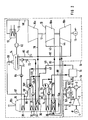
- a gas and steam turbine system according to FIG. 1 comprises a gas turbine system 1a and a steam turbine system 1b.
- a coal gasification plant 1c is connected upstream of the gas turbine plant 1a.
- the gas turbine system 1 a comprises a gas turbine 2 with a coupled air compressor 3 and generator 4 and a combustion chamber 5 connected upstream of the gas turbine 2, which is connected to a fresh air line 6 of the air compressor 3.
- the steam turbine system 1b comprises a steam turbine 10 with a coupled generator 11 and, in a water-steam circuit 12, a condenser 13 connected downstream of the steam turbine 10 and a feed water container 14 connected downstream of the condenser, and a steam generator 15.
- the steam turbine 10 consists of a high-pressure part 10a, a medium-pressure part 10b and a low-pressure part 10c, which drive the generator 11 via a common shaft 17.
- an exhaust pipe 9 is connected to an inlet 15a of the steam generator 15.
- the exhaust gas A leaves the steam generator 15 via its outlet 15b in the direction of a chimney, not shown.
- the steam generator 15 comprises a high-pressure preheater or economizer 20, a low-pressure heating device 22, a high-pressure heating device 24 and a reheater 26.
- the low-pressure heating device 22 consists of a preheater 28, an evaporator 30 and a superheater 32, which together with the low-pressure part 10c of the steam turbine 10 and a water-steam drum 34 form the low-pressure stage of the water-steam circuit 12.
- the high-pressure heating device 24 comprises an evaporator 36 and a superheater 38, which together with the high-pressure part 10 a of the steam turbine 10 and with the economizer 20 and a water-steam drum 40 form the high-pressure stage of the water-steam circuit 12.
- the reheater 26 is connected on the inlet side via a steam line 42 to the high pressure part 10a and on the outlet side via a steam line 44 to the medium pressure part 10b of the steam turbine 10.
- An outflow line 46 is connected to the water-steam circuit 12 in the flow direction of the water behind the economizer 20 and leads via a three-way valve 48 into the coal gasification plant 1c.
- a heat exchanger 50 which is arranged on the primary side in the water-steam drum 40, is connected to the outflow line 46.
- the combustion chamber 5 is optionally supplied as fuel coal gas KG from the coal gasification system 1c via a supply line 52 or natural gas EG via a supply line 53.
- a flap 54 is actuated, which in the exemplary embodiment lies in the feed line 52.
- the fuel KG or EG is burned in the combustion chamber 5 with the compressed fresh air L from the air compressor 3.
- the hot flue gas RG produced during the combustion is passed into the gas turbine 2 via a flue gas line 8. It relaxes there and drives the gas turbine 2. This in turn drives the air compressor 3 and the generator 4.
- the hot exhaust gas AG emerging from the gas turbine 2 is introduced into the steam generator 15 via an exhaust gas line 9 and is used there to generate steam for the steam turbine 10.
- the exhaust gas flow and the water-steam circuit 12 are linked to one another in countercurrent.
- the steam emerging from the low-pressure part 10c of the steam turbine 10 is fed to the condenser 13 via a steam line 60 and condenses there.
- the condensate is pumped into the feed water tank 14 via a condensate pump 62.
- water is pumped via a circulating pump 64 into the preheater 28 of the low-pressure heating device 22 and preheated there.
- the water preheated in the preheater 28 flows via a line 66, into which a valve 68 is connected, into the water-steam drum 34.
- the water is then evaporated using the evaporator 30.
- water is pumped out of the water-steam drum 34 with the aid of a pump 35 into the evaporator 30 and from there back into the water-steam drum 34.
- An adjustable portion of the preheated water flows back into the feed water tank 14 via a line 67, into which a valve 69 is connected.
- the steam separated in the water-steam drum 34 is fed to the superheater 32 and flows from there in the superheated state via a steam line 70 into the low-pressure part 10c of the steam turbine 10.
- the water supplied to the high-pressure stage from the feed water tank 14 is first pumped into the high-pressure preheater or economizer 20 via a high-pressure pump 71 and a valve 72 and warmed up there.
- a portion b of the warmed-up water that can be adjusted with a valve 74 flows into the water-steam drum 1 40 via a line 76.
- the water is then evaporated using the evaporator 36, water from the water-steam drum 40 using a pump 41 is pumped into the evaporator 36 and from there back into the water-steam drum 40.
- the one formed in the water-steam drum 40 Steam flows via a line 78 into the superheater 38 and from there in the superheated state via a steam line 80 into the high-pressure part 10a of the steam turbine 10.
- the steam relaxed in the high-pressure part 10a flows via the line 42 into the reheater 26 and from there into the medium-pressure part 10b of the steam turbine 10.
- the steam expanded in the medium pressure part 10b flows via a steam line 82, into which the steam line 70 opens, together with the steam from the low pressure superheater 32 into the low pressure part 10c of the steam turbine 10.
- Part of that from the medium pressure part 10b of the steam turbine 10 flowing steam flows with the valve 84 open via a steam line 86 into the feed water tank 14.
- the heating surfaces of the high-pressure preheater or economizer 20 are designed for natural gas operation.
- the temperature of the water withdrawn from the water-steam circuit 12 via the outflow line 46 is adjusted by mixing with a portion a of the withdrawn water conducted in a loop 51 through the heat exchanger 50.
- the temperature of the partial amount a is increased by absorbing heat generated in the evaporator 36, so that a suitable mixing temperature corresponding to the target temperature is set on the outflow side by suitable adjustment of the three-way valve 48.
- the water set to the desired temperature flows via line 46 into the coal gasification plant 1c and is evaporated there by means of indirect heat exchange with raw gas generated in the coal gasification process.
- Plant 1 described in the exemplary embodiment according to FIG. 1 is particularly suitable for retrofitting an existing plant 1 designed for natural gas operation with a coal gasification plant 1c.
- the heating surfaces of the economizer or high-pressure preheater 20 are designed for coal gas operation.
- the gas turbine system 1a with the coal gasification system 1c connected to it and the steam turbine system 1b are constructed as in the schematic illustration in accordance with FIG.
- the heat exchanger 50 ′ is arranged on the primary side in the water-steam drum 34 and is therefore integrated in the water-steam circuit 12 in the low-pressure stage.
- water removed from the water-steam circuit 12 in the flow direction of the water behind the economizer 20 and fed to the coal gasification plant 1c via the outflow line 46 is cooled by releasing excess heat to the low-pressure stage.
- the partial amount a 'of the water removed which is likewise carried out in a loop 51', is changed by indirect heat exchange with the water of the water-steam drum 34 such that mixing the removed water with the partial amount a 'with suitable adjustment of the valve 48 on the outflow side in line 46 sets the target temperature.
- the dimensions of the heat exchanger 50 '- as well as those of the heat exchanger 50 according to FIG. 1 - can be chosen to be so small due to the particularly good heat transfer from water to water or from water to steam that the heat exchanger 50 (FIG. 1) or 50' (FIG 2) can be installed in an existing drum 34 or 40 with little effort.
- the heating surfaces of the economizer 20 are evaporated by releasing the heat of the water heated in the economizer 20 at high pressure to the low-pressure stage. Steam is also generated there.
- the transition from natural gas to coal gas operation takes place by means of stepless heat transfer via the heat exchanger 50 '.
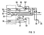
- the heat exchanger 50 ' is connected on the outlet side to the water-steam drum 40 of the high-pressure stage via a line 90 opening into the line 76.
- the exemplary embodiment according to FIG. 3 in which only the partial stream a 'of the water removed, which is guided in the loop 51', is cooled, in the exemplary embodiment according to FIG. 3 all of the water flowing into the water-steam drum 40 of the high-pressure stage is cooled.
- the circuit of the heat exchanger according to FIG. 2 has the advantage over the variant according to FIG. 3 that the heat exchanger 50 'is only to be designed for the partial flow a' carried in the loop 51 '.
- the heat exchanger 50 ' is only to be designed for the partial flow a' carried in the loop 51 '.
- Fiogur 2 a maximum of high-pressure steam is produced, so that a particularly high degree of efficiency is achieved.
- the valve 74 must be designed to regulate water near the boiling point.
Landscapes
- Engineering & Computer Science (AREA)
- Chemical & Material Sciences (AREA)
- Combustion & Propulsion (AREA)
- Mechanical Engineering (AREA)
- General Engineering & Computer Science (AREA)
- Engine Equipment That Uses Special Cycles (AREA)
Description
- Die Erfindung betrifft ein Verfahren zum Betreiben einer Gas- und Dampfturbinenanlage, wobei die im entspannten Arbeitsmittel der Gasturbine enthaltene Wärme zur Erzeugung von Dampf in einem Wasser-Dampf-Kreislauf der Dampfturbine genutzt und zum Aufheizen des Arbeitsmittels Gas verwendet wird, und wobei dem Wasser-Dampf-Kreislauf vorgewärmtes Wasser für einen Kohlevergasungsprozeß entnommen wird. Sie richtet sich weiter auf eine nach diesem Verfahren arbeitende Gas- und Dampfturbinenanlage. Ein derartiges Verfahren und eine derartige Anlage sind z.B. aus VGB Kraftwerkstechnik, Band 71, Nr.7, Juli 1991, S. 619 - 631 (vgl. insbesondere Bild 4) bekannt.
- Bei einer Gas- und Dampfturbinenanlage, die wahlweise mit Kohlegas oder mit Erdgas oder Öl betrieben werden kann, wird die im Abgas der Gasturbine enthaltene Wärme zur Erzeugung von Dampf für die Dampfturbine genutzt. Dabei umfaßt der Wasser-Dampf-Kreislauf der Dampfturbine üblicherweise zwei Druckstufen, die jeweils aus einem Vorwärmer sowie einem Verdampfer und einem Überhitzer aufgebaut sind. Bei einer Anlage mit integrierter Kohlevergasung wird üblicherweise dem Wasser-Dampf-Kreislauf vorgewärmtes Wasser zur Kühlung von bei der Kohlevergasung erzeugtem Rohgas entnommen. Dort erzeugter Dampf wird in den Wasser-Dampf-Kreislauf zurückgeführt. Bei einer mit Erdgas betriebenen Anlage ist eine derartige Wasserentnahme und Dampfeinspeisung nicht erforderlich.
- Für den Fall, daß die im Dampferzeuger angeordneten Heizflächen der Vorwärmer, Verdampfer und Überhitzer für Kohlegasbetrieb ausgelegt sind, sind insbesondere die Heizflächen des Hochdruck-Vorwärmers oder Economizers für den Erdgasbetrieb zu groß. Dadurch besteht bei Erdgasbetrieb aufgrund der im Vergleich zum Kohlegasbetrieb zu geringen Wasser-Dampf-Menge die Gefahr einer Verdampfung des Wassers im Economizer, so daß Überhitzungen und/oder Korrosionsschäden an den Heizflächen auftreten können. Demgegenüber sind für den Fall, daß die Heizflächen im Dampferzeuger für Erdgasbetrieb ausgelegt sind, die Heizflächen des Economizers für Kohlegasbetrieb zu klein.
- Bei einer aus der EP-OS-0 410 111 bekannten Gas- und Dampfturbinenanlage sind die Heizflächen im Dampferzeuger für Kohlegasbetrieb ausgelegt. Dabei wird bei Teillastbetrieb, bei dem im Vergleich zum Vollastbetrieb die Wasser-Dampf-Menge im Wasser-Dampf-Kreislauf, ähnlich wie bei Erdgasbetrieb, verhältnismäßig gering ist, die durch die Heizflächen des Vorwärmers oder Economizers strömende Wassermenge so weit erhöht, daß dort keine Verdampfung auftreten kann. Eine für die Dampferzeugung nicht benötigte Teilmenge des Speisewassers wird in zwei aufeinanderfolgenden Entspannungsstufen entspannt; anschließend wird der dabei gebildete Dampf im Dampferzeuger überhitzt und der Dampfturbine zugeführt. Dabei treten allerdings in jeder Entspannungsstufe thermodynamische Verluste auf, so daß der Gesamtwirkungsgrad der Anlage sinkt.
- Der Erfindung liegt daher die Aufgabe zugrunde, ein Verfahren zum Betreiben einer Gas- und Dampfturbinenanlage anzugeben, bei dem sowohl bei Kohlegasbetrieb als auch bei Erdgasbetrieb ein möglichst hoher Gesamtwirkungsgrad auch im Teillastbetrieb erreicht wird. Dies soll bei einer derartigen Anlage mit einem möglichst geringen technischen Aufwand erreicht werden.
- Bezüglich des Verfahrens wird diese Aufgabe erfindungsgemäß dadurch gelöst, daß die Solltemperatur des entnommenen Wassers durch Mischen mit einer Teilmenge des entnommenen Wassers eingestellt wird, wobei die Temperatur der Teilmenge des Wassers in einer mit dem Wasser-Dampf-Kreislauf gekoppelten Schleife verändert wird. Dabei wird vorteilhafterweise das Wasser dem Hochdruck-Vorwärmer (Economizer) entnommen, dessen Heizflächen primärseitig in den Dampferzeuger und sekundärseitig in den Wasser-Dampf-Kreislauf geschaltet sind.
- Für den Fall, daß die Heizflächen im Dampferzeuger, insbesondere die Heizflächen des Economizers, für Erdgasbetrieb ausgelegt sind, wird die Teilmenge des entnommenen Wassers durch indirekten Wärmetausch mit Wasser einer Wasser-Dampf-Trommel der Hochdruckstufe aufgewärmt. Die Solltemperatur des für den Kohlevergasungsprozeß entnommenen Wassers wird somit durch Auskoppeln von Wärme aus der Hochdruckstufe, in deren Verdampfer-Heizflächen genügend Wärme erzeugt wird, erreicht.
- Für den Fall, daß die Heizflächen im Dampferzeuger, insbesonder die Heizflächen des Economizers, für Kohlegasbetrieb ausgelegt sind, wird die Teilmenge des entnommenen Wassers durch indirekten Wärmetausch mit Wasser einer Wasser-Dampf-Trommel der Niederdruckstufe abgekühlt. Dadurch wird einerseits bei Erdgasbetrieb ein Ausdampfen der Heizflächen des Economizers durch Abgabe von Wärme des im Economizer unter erhöhtem Druck aufgeheizten Wassers an die Niederdruckstufe erreicht, so daß dort zusätzlich Dampf erzeugt wird. Andererseits wird bei Kohlegasbetrieb durch Abkühlen des entnommenen Wassers eine Verdampfung des Wassers auf dem Weg zum Kohlevergasungsprozeß sicher vermieden. Außerdem wird die Kapazität des entnommenen Wassers zur Aufnahme von Wärme aus dem Kohlevergasungsprozeß erhöht.
- Das im Kohlevergasungsprozeß aufgewärmte Wasser wird vorteilhafterweise in den Wasser-Dampf-Kreislauf zurückgeführt.
- Bezüglich der Anlage mit einem der Gasturbine nachgeschalteten Dampferzeuger, der einen in den Wasser-Dampf-Kreislauf der Dampfturbine geschalteten Vorwärmer (Economizer) und eine dem Vorwärmer nachgeschaltete Heizeinrichtung einer Hochdruckstufe sowie eine dem Vorwärmer vorgeschaltete Heizeinrichtung einer Niederdruckstufe umfaßt, wird die gestellte Aufgabe erfindungsgemäß gelöst durch einen Wärmetauscher, der primärseitig im Bereich zwischen der Niederdruckstufe und der Hochdruckstufe in den Wasser-Dampf-Kreislauf integriert ist und der sekundärseitig einer in Strömungsrichtung des Wassers hinter dem Vorwärmer an den Wasser-Dampf-Kreislauf angeschlossenen und in eine Kohlevergasungsanlage führenden Abströmleitung parallel geschaltet ist.
- Zum Einstellen oder Regeln der Solltemperatur des entnommenen Wassers ist vorteilhafterweise eine in der Abströmleitung liegende Mischvorrichtung vorgesehen, in die der Wärmetauscher mündet. Als Mischvorrichtung dient beispielsweise ein Drei-Wege-Ventil.
- Bei Auslegung der Heizflächen des Economizers für Erdgasbetrieb ist vorteilhafterweise der Wärmetauscher in einer Wasser-Dampf-Trommel der Hochdruckstufe angeordnet. Dagegen ist bei Auslegung der Heizflächen des Economizers für Kohlegasbetrieb der Wärmetauscher vorteilhafterweise in einer Wasser-Dampf-Trommel der Niederdruckstufe angeordnet. Dabei kann der Wärmetauscher ausgangsseitig an die Wasser-Dampf-Trommel der Hochdruckstufe angeschlossen sein.
- Die mit der Erfindung erzielten Vorteile bestehen insbesondere darin, daß in den Heizflächen des Dampferzeugers auch bei extremen Betriebsbedingungen, also auch in unterschiedlichen Lastbereichen, sowohl bei Kohlegasbetrieb als auch bei Erdgasbetrieb keine oder nur geringe den thermodynamischen Kreisprozeß beeinträchtigende Drosselverluste entstehen. Dadurch treten nur innerhalb zulässiger Grenzen liegende Betriebszustände auf. Beim Übergang von Erdgasbetrieb auf Kohlegasbetrieb und umgekehrt erfolgt eine stufenlose Wärmeverschiebung über den Wärmetauscher.
- Zur näheren Erläuterung der Erfindung werden anhand einer Zeichnung Ausführungsbeispiele beschrieben; darin zeigen:
- FIG 1
- eine schematische Darstellung einer Gas- und Dampfturbinenanlage mit einem Wärmetauscher in einer Wasser-Dampf-Trommel einer Hochdruckstufe,
- FIG 2
- eine Anlage gemäß Figur 1 mit einem Wärmetauscher in einer Wasser-Dampf-Trommel einer Niederdruckstufe und
- FIG 3
- im Ausschnitt eine Anlage gemäß Figur 2 mit einer weiteren Schaltung des Wärmetauschers.
- Einander entsprechende Teile sind in allen Figuren mit den gleichen Bezugszeichen versehen.
- Eine Gas- und Dampfturbinenanlage gemäß Figur 1 umfaßt eine Gasturbinenanlage 1a und eine Dampfturbinenanlage 1b. Der Gasturbinenanlage 1a ist eine Kohlevergasungsanlage 1c vorgeschaltet. Die Gasturbinenanlage 1a umfaßt eine Gasturbine 2 mit angekoppeltem Luftverdichter 3 und Generator 4 sowie eine der Gasturbine 2 vorgeschaltete Brennkammer 5, die an eine Frischluftleitung 6 des Luftverdichters 3 angeschlossen ist.
- Die Dampfturbinenanlage 1b umfaßt eine Dampfturbine 10 mit angekoppeltem Generator 11 und in einem Wasser-Dampf-Kreislauf 12 einen der Dampfturbine 10 nachgeschalteten Kondensator 13 und einen dem Kondensator nachgeschalteten Speisewasserbehälter 14 sowie einen Dampferzeuger 15.
- Die Dampfturbine 10 besteht aus einem Hochdruckteil 10a, einem Mitteldruckteil 10b und einem Niederdruckteil 10c, die über eine gemeinsame Welle 17 den Generator 11 antreiben.
- Zum Zuführen der Abgase A aus der Gasturbine 2 in den Dampferzeuger 15 ist eine Abgasleitung 9 an einen Eingang 15a des Dampferzeugers 15 angeschlossen. Das Abgas A verläßt den Dampferzeuger 15 über dessen Ausgang 15b in Richtung auf einen nicht dargestellten Kamin.
- Der Dampferzeuger 15 umfaßt einen Hochdruck-Vorwärmer oder Economizer 20, eine Niederdruck-Heizeinrichtung 22, eine Hochdruck-Heizeinrichtung 24 und einen Zwischenüberhitzer 26.
- Die Neiderdruck-Heizeinrichtung 22 besteht aus einem Vorwärmer 28, einem Verdampfer 30 und einem Überhitzer 32, die zusammen mit dem Niederdruckteil 10c der Dampfturbine 10 und einer Wasser-Dampf-Trommel 34 die Niederdruckstufe des Wasser-Dampf-Kreislaufs 12 bilden.
- Die Hochdruck-Heizeinrichtung 24 umfaßt einen Verdampfer 36 und einen Überhitzer 38, die zusammen mit dem Hochdruckteil 10a der Dampfturbine 10 sowie mit dem Economizer 20 und einer Wasser-Dampf-Trommel 40 die Hochdruckstufe des Wasser-Dampf-Kreislaufs 12 bilden.
- Der Zwischenüberhitzer 26 ist eingangsseitig über eine Dampfleitung 42 an den Hochdruckteil 10a und ausgangsseitig über eine Dampfleitung 44 an den Mitteldruckteil 10b der Dampfturbine 10 angeschlossen.
- An den Wasser-Dampf-Kreislauf 12 ist in Stömungsrichtung des Wassers hinter dem Economizer 20 eine Abströmleitung 46 angeschlossen, die über ein Dreiwegeventil 48 in die Kohlevergasungsanlage 1c führt. An die Abströmleitung 46 ist ein Wärmetauscher 50 sekundärseitig angeschlossen, der primärseitig in der Wasser-Dampf-Trommel 40 angeordnet ist.
- Beim Betrieb der Gas- und Dampfturbinenanlage 1 wird der Brennkammer 5 als Brennstoff Kohlegas KG aus der Kohlevergasungsanlage 1c über eine Zuführleitung 52 oder Erdgas EG über eine Zuführleitung 53 wahlweise zugeführt. Beim Übergang von Erdgasbetrieb auf Kohlegasbetrieb wird eine Klappe 54 betätigt, die im Ausführungsbeispiel in der Zuführleitung 52 liegt.
- Der Brennstoff KG oder EG wird in der Brennkammer 5 mit der verdichteten Frischluft L aus dem Luftverdichter 3 verbrannt. Das bei der Verbrennung entstehende heiße Rauchgas RG wird über eine Rauchgasleitung 8 in die Gasturbine 2 geleitet. Dort entspannt es sich und treibt dabei die Gasturbine 2 an. Diese wiederum treibt den Luftverdichter 3 und den Generator 4 an.
- Das aus der Gasturbine 2 austretende heiße Abgas AG wird über eine Abgasleitung 9 in den Dampferzeuger 15 eingeleitet und dort zur Erzeugung von Dampf für die Dampfturbine 10 genutzt. Zu diesem Zweck sind der Abgasstrom und der Wasser-Dampf-Kreislauf 12 im Gegenstrom miteinander verknüpft.
- Der aus dem Niederdruckteil 10c der Dampfturbine 10 austretende Dampf wird über eine Dampfleitung 60 dem Kondensator 13 zugeführt und kondensiert dort. Das Kondensat wird über eine Kondensatpumpe 62 in den Speisewasserbehälter 14 gepumpt. Aus dem Speisewasserbehälter 14 wird Wasser über eine Umwälz-Pumpe 64 in den Vorwärmer 28 der Niederdruck-Heizeinrichtung 22 gepumpt und dort vorgewärmt. Das im Vorwärmer 28 vorgewärmte Wasser strömt über eine Leitung 66, in die ein Ventil 68 geschaltet ist, in die Wasser-Dampf-Trommel 34. Danach wird das Wasser mit Hilfe des Verdampfers 30 verdampft. Dazu wird Wasser aus der Wasser-Dampf-Trommel 34 mit Hilfe einer Pumpe 35 in den Verdampfer 30 und von dort zurück in die Wasser-Dampf-Trommel 34 gepumpt. Eine einstellbare Teilmenge des vorgewärmten Wassers strömt über eine Leitung 67, in die ein Ventil 69 geschaltet ist, in den Speisewasserbehälter 14 zurück. Der in der Wasser-Dampf-Trommel 34 abgetrennte Dampf wird dem Überhitzer 32 zugeführt und strömt von dort in überhitztem Zustand über eine Dampfleitung 70 in den Niederdruckteil 10c der Dampfturbine 10.
- Das der Hochdruckstufe zugeführte Wasser aus dem Speisewasserbehälter 14 wird über eine Hochdruck-Pumpe 71 und ein Ventil 72 zunächst in den Hochdruck-Vorwärmer oder Economizer 20 gepumpt und dort aufgewärmt. Eine mit einem Ventil 74 einstellbare Teilmenge b des aufgewärmten Wassers strömt über eine Leitung 76 in die Wasser-Dampf-Tromme1 40. Anschließend wird das Wasser mit Hilfe des Verdampfers 36 verdampft, wobei Wasser aus der Wasser-Dampf-Trommel 40 mittels einer Pumpe 41 in den Verdampfer 36 und von dort zurück in die Wasser-Dampf-Trommel 40 gepumpt wird. Der in der Wasser-Dampf-Trommel 40 gebildete Dampf strömt über eine Leitung 78 in den Überhitzer 38 und von dort in überhitztem Zustand über eine Dampfleitung 80 in den Hochdruckteil 10a der Dampfturbine 10. Der im Hochdruckteil 10a entspannte Dampf strömt über die Leitung 42 in den Zwischenüberhitzer 26 und von dort in den Mitteldruckteil 10b der Dampfturbine 10. Der im Mitteldruckteil 10b entspannte Dampf strömt über eine Dampfleitung 82, in die die Dampfleitung 70 mündet, zusammen mit dem Dampf aus dem Niederdruck-Überhitzer 32 in den Niederdruckteil 10c der Dampfturbine 10. Ein Teil des aus dem Mitteldruckteil 10b der Dampfturbine 10 abströmenden Dampfes strömt bei geöffnetem Ventil 84 über eine Dampfleitung 86 in den Speisewasserbehälter 14.
- Im Ausführungsbeispiel gemäß Figur 1 sind die Heizflächen des Hochdruck-Vorwärmers oder Economizers 20 für Erdgasbetrieb ausgelegt. Bei Kohlegasbetrieb wird die Temperatur des dem Wasser-Dampf-Kreislauf 12 über die Abströmleitung 46 entnommenen Wassers durch Mischen mit einer in einer Schleife 51 durch den Wärmetauscher 50 geführten Teilmenge a des entnommenen Wassers eingestellt. Dabei wird die Temperatur der Teilmenge a durch Aufnahme von im Verdampfer 36 erzeugter Wärme erhöht, so daß sich durch geeignete Einstellung des Drei-Wege-Ventils 48 auf dessen Abströmseite eine der Solltemperatur entsprechende Mischtemperatur einstellt. Das auf die gewünschte Temperatur eingestellte Wasser strömt über die Leitung 46 in die Kohlevergasungsanlage 1c und wird dort durch indirekten Wärmetausch mit bei dem Kohlevergasungsprozeß erzeugtem Rohgas verdampft. Der in der Kohlevergasungsanlage 1c erzeugte Dampf strömt über eine Leitung 88, die an die Leitung 78 angeschlossen ist, in den Überhitzer 38 und wird somit dem Wasser-Dampf-Kreislauf 12 wieder zugeführt. Die im Ausführungsbeispiel gemäß Figur 1 beschriebene Anlage 1 eignet sich insbesondere zur Nachrüstung einer bestehenden, für Erdgasbetrieb ausgelegten Anlage 1 mit einer Kohlevergasungsanlage 1c.
- Beim Ausführungsbeispiel gemäß Figur 2 sind die Heizflächen des Economizers oder Hochdruck-Vorwärmers 20 für Kohlegasbetrieb ausgelegt. Im übrigen sind in der schematischen Darstellung in Figur 2 die Gasturbinenanlage 1a mit der daran angeschlossenen Kohlevergasungsanlage 1c und die Dampfturbinenanlage 1b wie in der schematischen Darstellung gemäß Figur 1 aufgebaut. In diesem Fall ist der Wärmetauscher 50' primärseitig in der Wasser-Dampf-Trommel 34 angeordnet und somit im Wasser-Dampf-Kreislauf 12 in die Niederdruckstufe integriert.
- Bei Kohlegasbetrieb wird dem Wasser-Dampf-Kreislauf 12 in Strömungsrichtung des Wassers hinter dem Economizer 20 entnommenes und der Kohlevergasungsanlage 1c über die Abströmleitung 46 zugeführtes Wasser durch Abgabe von überschüssiger Wärme an die Niederdruckstufe abgekühlt. Dazu wird die ebenfalls in einer Schleife 51' geführte Teilmenge a' des entnommenen Wassers durch indirekten Wärmetausch mit dem Wasser der Wasser-Dampf-Trommel 34 derart verändert, daß sich durch Mischen des entnommenen Wassers mit der Teilmenge a' bei geeigneter Einstellung des Ventils 48 auf dessen Abströmseite in der Leitung 46 die Solltemperatur einstellt.
- Die Abmessungen des Wärmetauschers 50' - ebenso wie die des Wärmetauschers 50 gemäß Figur 1 - können aufgrund des besonders guten Wärmeübergangs von Wasser zu Wasser oder von Wasser zu Dampf so klein gewählt werden, daß der Wärmetauscher 50 (Figur 1) oder 50' (Figur 2) mit geringem Aufwand in eine bereits vorhandene Trommel 34 bzw. 40 installiert werden kann.
- Bei Erdgasbetrieb wird ein Ausdampfen der Heizflächen des Economizers 20 durch Abgabe von Wärme des im Economizer 20 bei hohem Druck aufgeheizten Wassers an die Niederdruckstufe erreicht. Dort wird zusätzlich Dampf erzeugt. Der Übergang von Erdgas- auf Kohlegasbetrieb erfolgt durch stufenlose Wärmeverschiebung über den Wärmetauscher 50'.
- Bei Kohlegasbetrieb wird durch Abkühlen des entnommenen Wassers eine Verdampfung des Wassers in der Abströmleitung 46 sicher vermieden. Außerdem wird die Kapazität des entnommenen Wassers zur Aufnahme von Wärme aus dem bei dem Kohlevergasungsprozeß erzeugten Rohgas erhöht.
- Bei der in Figur 3 im Ausschnitt dargestellten Anlage ist der Wärmetauscher 50' ausgangsseitig über eine in die Leitung 76 mündende Leitung 90 mit der Wasser-Dampf-Trommel 40 der Hochdruckstufe verbunden. Dabei wird im Gegensatz zum Ausführungsbeispiel gemäß Figur 2, bei dem nur der in der Schleife 51' geführte Teilstrom a' des entnommenen Wassers abgekühlt wird, im Ausführungsbeispiel gemäß Figur 3 das gesamte in die Wasser-Dampf-Trommel 40 der Hochdruckstufe strömende Wasser abgekühlt.
- Die Schaltung des Wärmetauschers gemäß Figur 2 hat gegenüber der Variante gemäß Figur 3 den Vorteil, daß der Wärmetauscher 50' lediglich für den in der Schleife 51' geführten Teilstrom a' auszulegen ist. Bei der Variante gemäß Fiogur 2 wird ein Maximum an Hochdruckdampf produziert, so daß ein besonders hoher Wirkungsgrad erreicht wird. Dabei muß allerdings, im Gegensatz zur Variante gemläß Figur 3, das Ventil 74 zur Regelung von Wasser in Siedepunktnähe ausgelegt sein.
- Beim Übergang von einer Gasart auf die andere, insbesondere beim Übergang von Kohlegasbetrieb auf Erdgasbetrieb, bei dem eine um die der Kohlevergasung zuzuführenden Wassermenge verringerte Wasser-Dampf-Menge bewegt werden muß, ist es zweckmäßig, den Druck im Economizer 20 anzuheben, so daß zum Wärmetauscher 50' nur Wasser strömt.
- Ähnlich wie beim Erdgasbetrieb wird auch bei Teillastbetrieb, bei dem im Dampferzeuger 15 vermehrt Wärme in den Bereich der Heizflächen des Economizers 20 gelangt, durch Einschalten des Wärmetauschers 50 (Figur 1) oder 50' (Figuren 2 und 3) in den Wasser-Dampf-Kreislauf 12 ein Ausdampfen im Economizer 20 vermieden.
Claims (10)
- Verfahren zum Betreiben einer Gas- und Dampfturbinenanlage, wobei die im entspannten Arbeitsmittel (RG) der Gasturbine (2) enthaltene Wärme zur Erzeugung von Dampf in einem Wasser-Dampf-Kreislauf (12) der Dampfturbine (10) genutzt und zum Aufheizen des Arbeitsmittels (RG) Gas verwendet wird, und wobei dem Wasser-Dampf-Kreislauf (12) vorgewärmtes Wasser für einen Kohlevergasungsprozeß entnommen wird,
dadurch gekennzeichnet,
daß die Solltemperatur des entnommenen Wassers durch Mischen mit einer Teilmenge (a, a') des entnommenen Wassers eingestellt wird, indem die Temperatur der Teilmenge (a, a') in einer mit dem Wasser-Dampf-Kreislauf (12) gekoppelten Schleife (50, 51') verändert wird. - Verfahren nach Anspruch 1,
dadurch gekennzeichnet, daß das Wasser einem Hochdruck-Vorwärmer (20) entnommen wird, dessen Heizflächen primärseitig in den Dampferzeuger (15) und sekundärseitig in den Wasser-Dampf-Kreislauf (12) geschaltet sind. - Verfahren nach Anspruch 1 oder 2,
dadurch gekennzeichnet, daß die Teilmenge (a) des entnommenen Wassers durch indirekten Wärmetausch mit Wasser einer Wasser-Dampf-Trommel (40) der Hochdruckstufe aufgewärmt wird (Figur 1). - Verfahren nach Anspruch 1 oder 2,
dadurch gekennzeichnet, daß die Teilmenge (a') des entnommenen Wassers durch indirekten Wärmetausch mit Wasser einer Wasser-Dampf-Trommel (40) der Niederdruckstufe abgekühlt wird (Figuren 2 und 3). - Verfahren nach einem der Ansprüche 1 bis 4,
dadurch gekennzeichnet, daß das im Kohlevergasungsprozeß aufgeheizte Wasser in den Wasser-Dampf-Kreislauf (12) zurückgeführt wird. - Gas- und Dampfturbinenanlage mit einem der Gasturbine (2) nachgeschalteten Dampferzeuger (15), der einen in den Wasser-Dampf-Kreislauf (12) der Dampfturbine (10) geschalteten Vorwärmer (20) und eine dem Vorwärmer (20) nachgeschaltete Heizeinrichtung (24) einer Hochdruckstufe sowie eine dem Vorwärmer (20) vorgeschaltete Heizeinrichtung (22) einer Niederdruckstufe umfaßt, insbesondere zur Durchführung des Verfahrens nach einem der Ansprüche 1 bis 5, gekennzeichnet durch einen Wärmetauscher (50, 50'), der primärseitig im Bereich zwischen der Niederdruckstufe und der Hochdruckstufe in den Wasser-Dampf-Kreislauf (12) integriert ist, und der sekundärseitig einer in Strömungsrichtung des Wassers hinter dem Vorwärmer (20) an den Wasser-Dampf-Kreislauf (12) angeschlossenen und in eine Kohlevergasungsanlage (1c) führenden Abströmleitung (46) parallel geschaltet ist.
- Anlage nach Anspruch 6,
dadurch gekennzeichnet, daß der Wärmetauscher (50, 50') in eine in der Abströmleitung (46) liegende Mischvorrichtung (48), vorzugsweise ein Drei-Wege-Ventil, mündet. - Anlage nach Anspruch 6 oder 7,
dadurch gekennzeichnet, daß der Wärmetauscher (50) in einer Wasser-Dampf-Trommel (40) der Hochdruckstufe angeordnet ist (Figur 1). - Anlage nach Anspruch 6 oder 7,
dadurch gekennzeichnet, daß der Wärmetauscher (50') in einer Wasser-Dampf-Trommel (34) der Niederdruckstufe angeordnet ist (Figuren 2 und 3). - Anlage nach Anspruch 9,
dadurch gekennzeichnet, daß der Wärmetauscher (50') ausgangsseitig an die Waser-Dampf-Trommel (40) der Hochdruckstufe angeschlossen ist (Figur 3).
Applications Claiming Priority (2)
| Application Number | Priority Date | Filing Date | Title |
|---|---|---|---|
| DE4123731 | 1991-07-17 | ||
| DE4123731 | 1991-07-17 |
Publications (2)
| Publication Number | Publication Date |
|---|---|
| EP0523466A1 EP0523466A1 (de) | 1993-01-20 |
| EP0523466B1 true EP0523466B1 (de) | 1995-10-04 |
Family
ID=6436391
Family Applications (1)
| Application Number | Title | Priority Date | Filing Date |
|---|---|---|---|
| EP92111270A Expired - Lifetime EP0523466B1 (de) | 1991-07-17 | 1992-07-03 | Verfahren zum Betreiben einer Gas- und Dampfturbinenanlage und Anlage zur Durchführung des Verfahrens |
Country Status (3)
| Country | Link |
|---|---|
| US (2) | US5285627A (de) |
| EP (1) | EP0523466B1 (de) |
| DE (1) | DE59203883D1 (de) |
Families Citing this family (18)
| Publication number | Priority date | Publication date | Assignee | Title |
|---|---|---|---|---|
| JP3315800B2 (ja) * | 1994-02-22 | 2002-08-19 | 株式会社日立製作所 | 蒸気タービン発電プラント及び蒸気タービン |
| DE4409811C1 (de) * | 1994-03-22 | 1995-05-18 | Siemens Ag | Verfahren zum Betreiben eines Abhitzedampferzeugers sowie danach arbeitender Abhitzedampferzeuger |
| DE4446862C2 (de) * | 1994-12-27 | 1998-01-29 | Siemens Ag | Verfahren zur Kühlung des Kühlmittels einer Gasturbine und Vorrichtung zur Durchführung des Verfahrens |
| DE19527537C1 (de) * | 1995-07-27 | 1996-09-26 | Siemens Ag | Verfahren zum Betreiben einer Gas- und Dampfturbinenanlage sowie danach arbeitende Anlage |
| EP0759499B2 (de) * | 1995-08-21 | 2005-12-14 | Hitachi, Ltd. | Dampfturbinenkraftanlage und Dampfturbine |
| SE0004931D0 (sv) * | 2000-12-29 | 2000-12-29 | Addpower Ab | Sätt att konvertera värme i varma rökgaser |
| EP1365109A1 (de) * | 2002-05-22 | 2003-11-26 | Siemens Aktiengesellschaft | Dampfturbine |
| US20080127647A1 (en) * | 2006-09-15 | 2008-06-05 | Skyfuel, Inc. | Solar-Generated Steam Retrofit for Supplementing Natural-Gas Combustion at Combined Cycle Power Plants |
| USD565893S1 (en) | 2006-12-22 | 2008-04-08 | Electrolux Home Products, Inc. | Portion of a burner assembly |
| USD562069S1 (en) | 2006-12-22 | 2008-02-19 | Electrolux Home Products, Inc. | Portion of a burner assembly |
| USD562070S1 (en) | 2006-12-22 | 2008-02-19 | Electrolux Home Products | Portion of a burner assembly |
| US7871264B2 (en) * | 2006-12-29 | 2011-01-18 | Electrolux Home Products, Inc. | Hub and spoke burner port configuration |
| AU2009268667A1 (en) * | 2008-07-09 | 2010-01-14 | Skyfuel, Inc. | Solar collectors having slidably removable reflective panels for use in solar thermal applications |
| WO2010006193A1 (en) | 2008-07-09 | 2010-01-14 | Skyfuel, Inc. | Space frame connector |
| WO2010022280A1 (en) * | 2008-08-22 | 2010-02-25 | Skyfuel, Inc. | Hydraulic-based rotational system for solar concentrators that resists high wind loads without a mechanical lock |
| WO2010083292A1 (en) * | 2009-01-14 | 2010-07-22 | Skyfuel, Inc. | Apparatus and method for building linear solar collectors directly from rolls of reflective laminate material |
| JP6433714B2 (ja) * | 2014-08-11 | 2018-12-05 | 三菱日立パワーシステムズ株式会社 | ガス化複合発電設備、およびガス化複合発電設備の運転方法 |
| FI131342B1 (fi) * | 2021-11-10 | 2025-02-28 | Loeytty Ari Veli Olavi | Menetelmä ja laitteisto energiahäviöiden pienentämiseksi kaasuturbiini kombilaitoksissa |
Family Cites Families (13)
| Publication number | Priority date | Publication date | Assignee | Title |
|---|---|---|---|---|
| US2675672A (en) * | 1954-04-20 | Schsrner | ||
| DE2246407C2 (de) * | 1972-09-21 | 1982-02-18 | Krupp-Koppers Gmbh, 4300 Essen | Verfahren zum Erzeugen elektrischer Energie |
| CH623888A5 (de) * | 1977-10-04 | 1981-06-30 | Bbc Brown Boveri & Cie | |
| DE2743830C2 (de) * | 1977-09-29 | 1984-03-22 | Saarbergwerke AG, 6600 Saarbrücken | Verfahren zum Betreiben einer kombinierten Gas-Dampfkraftanlage und Gas-Dampfkraftanlage zur Durchführung des Verfahrens |
| US4288979A (en) * | 1979-09-21 | 1981-09-15 | Combustion Engineering, Inc. | Combined cycle power plant incorporating coal gasification |
| EP0062932B1 (de) * | 1981-04-03 | 1984-12-05 | BBC Aktiengesellschaft Brown, Boveri & Cie. | Kombiniertes Gas-Dampfturbinen-Kraftwerk |
| JPS58211511A (ja) * | 1982-06-02 | 1983-12-09 | Hitachi Ltd | 石炭ガス化複合発電プラント |
| JPS59229005A (ja) * | 1983-06-10 | 1984-12-22 | Hitachi Ltd | 石炭ガス化複合発電プラント |
| DE3408937A1 (de) * | 1984-01-31 | 1985-08-08 | BBC Aktiengesellschaft Brown, Boveri & Cie., Baden, Aargau | Kombinierte gas-/dampf-kraftwerkanlage |
| US4693072A (en) * | 1986-08-25 | 1987-09-15 | Acec Power Systems Limited | Method of operating a combined cycle electric power plant |
| DE3804605A1 (de) * | 1988-02-12 | 1989-08-24 | Siemens Ag | Verfahren und anlage zur abhitzedampferzeugung |
| DE3921439A1 (de) * | 1989-06-27 | 1991-01-03 | Siemens Ag | Kombinierter gas-dampfturbinenprozess mit kohlevergasung |
| EP0410111B1 (de) * | 1989-07-27 | 1993-01-20 | Siemens Aktiengesellschaft | Abhitzedampferzeuger für ein Gas- und Dampfturbinenkraftwerk |
-
1992
- 1992-07-03 EP EP92111270A patent/EP0523466B1/de not_active Expired - Lifetime
- 1992-07-03 DE DE59203883T patent/DE59203883D1/de not_active Expired - Fee Related
- 1992-07-17 US US07/916,027 patent/US5285627A/en not_active Expired - Fee Related
-
1993
- 1993-11-22 US US08/156,061 patent/US5369949A/en not_active Expired - Fee Related
Also Published As
| Publication number | Publication date |
|---|---|
| DE59203883D1 (de) | 1995-11-09 |
| EP0523466A1 (de) | 1993-01-20 |
| US5369949A (en) | 1994-12-06 |
| US5285627A (en) | 1994-02-15 |
Similar Documents
| Publication | Publication Date | Title |
|---|---|---|
| EP0523467B1 (de) | Verfahren zum Betreiben einer Gas- und Dampfturbinenanlage und Anlage zur Durchführung des Verfahrens | |
| DE4434526C1 (de) | Verfahren zum Betreiben einer Gas- und Dampfturbinenanlage sowie danach arbeitende Anlage | |
| EP0819209B1 (de) | Verfahren zum betreiben eines abhitzedampferzeugers sowie danach arbeitender abhitzedampferzeuger | |
| EP0591163B1 (de) | Kombinierte gas- und dampfturbinenanlage | |
| EP2368021B1 (de) | Abhitzedampferzeuger sowie ein verfahren zum verbesserten betrieb eines abhitzedampferzeugers | |
| DE19736889C1 (de) | Verfahren zum Betreiben einer Gas- und Dampfturbinenanlage und Gas- und Dampfturbinenanlage zur Durchführung des Verfahrens | |
| EP0778397B1 (de) | Verfahren zum Betrieb einer mit einem Abhitzedampferzeuger und einem Dampfverbraucher kombinierten Gasturbogruppe | |
| EP0523466A1 (de) | Verfahren zum Betreiben einer Gas- und Dampfturbinenanlage und Anlage zur Durchführung des Verfahrens | |
| EP0898641B1 (de) | Gas- und dampfturbinenanlage sowie verfahren zu deren betrieb | |
| EP0515911B1 (de) | Verfahren zum Betreiben einer Gas- und Dampfturbinenanlage und entsprechende Anlage | |
| EP0526816A1 (de) | Gas- und Dampfturbinenkraftwerk mit einem solar beheizten Dampferzeuger | |
| EP1023526A1 (de) | Gas- und dampfturbinenanlage und verfahren zum betreiben einer derartigen anlage | |
| DE3213837A1 (de) | Abgasdampferzeuger mit entgaser | |
| DE4321081A1 (de) | Verfahren zum Betreiben einer Gas- und Dampfturbinenanlage sowie danach arbeitende GuD-Anlage | |
| EP3420202B1 (de) | Kondensatrezirkulation | |
| EP1105624A1 (de) | Gas- und dampfturbinenanlage | |
| EP0981681B1 (de) | Gas- und dampfturbinenanlage und verfahren zur kühlung des kühlmittels der gasturbine einer derartigen anlage | |
| EP0595009B1 (de) | Verfahren zum Betreiben einer Kraftwerksanlage sowie danach arbeitende Anlage | |
| EP0582898A1 (de) | Verfahren zum Betreiben einer Gas- und Dampfturbinenanlage sowie danach arbeitende Gud-Anlage | |
| EP1303684B1 (de) | Verfahren zum betreiben einer gas- und dampfturbinenanlage sowie entsprechende anlage | |
| EP0840837B1 (de) | Verfahren zum betreiben einer gas- und dampfturbinenanlage sowie danach arbeitende anlage | |
| DE19720789B4 (de) | Verfahren und Vorrichtung zur Erzeugung von Dampf | |
| EP1076761A1 (de) | Gas- und dampfturbinenanlage | |
| EP1425079B1 (de) | Verfahren und vorrichtung zur thermischen entgasung des arbeitsmittels eines zweiphasenprozesses | |
| EP1801363A1 (de) | Kraftwerksanlage |
Legal Events
| Date | Code | Title | Description |
|---|---|---|---|
| PUAI | Public reference made under article 153(3) epc to a published international application that has entered the european phase |
Free format text: ORIGINAL CODE: 0009012 |
|
| AK | Designated contracting states |
Kind code of ref document: A1 Designated state(s): DE ES GB |
|
| 17P | Request for examination filed |
Effective date: 19930709 |
|
| 17Q | First examination report despatched |
Effective date: 19950323 |
|
| GRAA | (expected) grant |
Free format text: ORIGINAL CODE: 0009210 |
|
| AK | Designated contracting states |
Kind code of ref document: B1 Designated state(s): DE ES GB |
|
| PG25 | Lapsed in a contracting state [announced via postgrant information from national office to epo] |
Ref country code: ES Free format text: THE PATENT HAS BEEN ANNULLED BY A DECISION OF A NATIONAL AUTHORITY Effective date: 19951004 |
|
| REF | Corresponds to: |
Ref document number: 59203883 Country of ref document: DE Date of ref document: 19951109 |
|
| GBT | Gb: translation of ep patent filed (gb section 77(6)(a)/1977) |
Effective date: 19951116 |
|
| PG25 | Lapsed in a contracting state [announced via postgrant information from national office to epo] |
Ref country code: GB Effective date: 19960703 |
|
| PLBE | No opposition filed within time limit |
Free format text: ORIGINAL CODE: 0009261 |
|
| STAA | Information on the status of an ep patent application or granted ep patent |
Free format text: STATUS: NO OPPOSITION FILED WITHIN TIME LIMIT |
|
| 26N | No opposition filed | ||
| GBPC | Gb: european patent ceased through non-payment of renewal fee |
Effective date: 19960703 |
|
| PG25 | Lapsed in a contracting state [announced via postgrant information from national office to epo] |
Ref country code: DE Effective date: 19970402 |