EP0521158A1 - Sheet feeding device - Google Patents
Sheet feeding device Download PDFInfo
- Publication number
- EP0521158A1 EP0521158A1 EP91906981A EP91906981A EP0521158A1 EP 0521158 A1 EP0521158 A1 EP 0521158A1 EP 91906981 A EP91906981 A EP 91906981A EP 91906981 A EP91906981 A EP 91906981A EP 0521158 A1 EP0521158 A1 EP 0521158A1
- Authority
- EP
- European Patent Office
- Prior art keywords
- sheet
- plate cylinder
- speed
- suction
- phase
- Prior art date
- Legal status (The legal status is an assumption and is not a legal conclusion. Google has not performed a legal analysis and makes no representation as to the accuracy of the status listed.)
- Granted
Links
- 238000007639 printing Methods 0.000 claims abstract description 25
- 238000001514 detection method Methods 0.000 claims description 10
- 238000010276 construction Methods 0.000 description 6
- 230000003247 decreasing effect Effects 0.000 description 3
- 239000000463 material Substances 0.000 description 2
- 238000005516 engineering process Methods 0.000 description 1
- 238000000034 method Methods 0.000 description 1
Images


Classifications
-
- B—PERFORMING OPERATIONS; TRANSPORTING
- B41—PRINTING; LINING MACHINES; TYPEWRITERS; STAMPS
- B41F—PRINTING MACHINES OR PRESSES
- B41F21/00—Devices for conveying sheets through printing apparatus or machines
-
- B—PERFORMING OPERATIONS; TRANSPORTING
- B41—PRINTING; LINING MACHINES; TYPEWRITERS; STAMPS
- B41F—PRINTING MACHINES OR PRESSES
- B41F33/00—Indicating, counting, warning, control or safety devices
- B41F33/04—Tripping devices or stop-motions
- B41F33/14—Automatic control of tripping devices by feelers, photoelectric devices, pneumatic devices, or other detectors
-
- B—PERFORMING OPERATIONS; TRANSPORTING
- B65—CONVEYING; PACKING; STORING; HANDLING THIN OR FILAMENTARY MATERIAL
- B65H—HANDLING THIN OR FILAMENTARY MATERIAL, e.g. SHEETS, WEBS, CABLES
- B65H3/00—Separating articles from piles
- B65H3/08—Separating articles from piles using pneumatic force
- B65H3/12—Suction bands, belts, or tables moving relatively to the pile
- B65H3/124—Suction bands or belts
- B65H3/126—Suction bands or belts separating from the bottom of pile
-
- B—PERFORMING OPERATIONS; TRANSPORTING
- B65—CONVEYING; PACKING; STORING; HANDLING THIN OR FILAMENTARY MATERIAL
- B65H—HANDLING THIN OR FILAMENTARY MATERIAL, e.g. SHEETS, WEBS, CABLES
- B65H9/00—Registering, e.g. orientating, articles; Devices therefor
Definitions
- a further object of this invention is to provide a sheet feeding apparatus enabling to correct parallel error against a plate cylinder.
- the sheet feeding apparatus of the first invention for feeding sheets piled up in a hopper, piece by piece, to a printing press from a suction conveyor installed at bottom of the hopper, comprising, a motor for driving the suction conveyor, a sensor positioned above the suction conveyor for detecting front edges of sheets being transferred, and a control unit for equalizing speed of the motor with speed of a plate cylinder of printing press and for adjusting phase of the sheet to phase of a press plate on the plate cylinder with a detection signal of the sensor, whereby sheet feeding accuracy is improved by correction of mechanical errors at suction of sheets.
- the sheets feeding apparatus of the second invention for feeding sheets piled up in a hopper, piece by piece, to a printing press from first and second suction conveyors installed in parallel at bottom of the hopper, comprising, a first motor for driving the first suction conveyor, a second motor for driving the second suction conveyor, a first sensor positioned above the first suction conveyor for detecting front edges of sheets being transferred, a second sensor positioned above the second suction conveyor for detecting front edges of sheets being transferred, a first control unit for equalizing speed of the first motor with speed of a plate cylinder of printing press and for adjusting phase of the sheet to phase of a press plate on the plate cylinder with a detection signal of the first sensor, and a secnd control unit for equalizing speed of the second motor with speed of the plate cylinder of printing press for adjusting phase of the sheet to phase of the press plate with the detection signal of the first sensor, and for correcting parallel error of the sheet against the press plate with detection signals of the first and second sensors, whereby sheet feeding accuracy is improved by correction of mechanical error
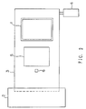
- Fig.1 shows the construction of an embodiment of the first invention.
- Fig.2 is a plan view of the embodiment shown in Fig.1.
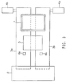
- Fig.3 is a plan view of an embodiment of the second invention.
- Fig.4 and Fig.5 show the construction of the embodiment shown in Fig.3.
- This sheet feeding apparatus includes a hopper 1 to pile up corrugated cardboard sheet 5, a suction conveyor 3 extended from bottom of the hopper to a plate cylinder 2 of a printing press, a servo motor 4 for driving the suction conveyor 3, and a sensor 6 provided to detect front edges of sheets for information of the suction conveyor 3.
- a timing belt is used for the suction conveyor 3, and non-slippery material is adhered to surface of the belt. Because the suction conveyor is not a feature of this invention, usual sanction conveyor can be used.
- the absolute position counter 18 which is cleared when the origin sensor 10 detects the origin of plate cylinder 2, is latched and outputs the value A.
- This value A expresses the absolute position of the front edge of press plate when the front edge of a sheet is detected.
- ⁇ L expresses the position difference between the front edge of sheet and the front edge of press plate, i.e. the position difference between the sheet 5 and the press plate 9.
- the suction conveyors 3a and 3b have a common vacuum gate 7 connected to the printing press line shaft (not shown in the figures), and a sheet 5 is taken out from the hopper 1 by up-and-down movement of this gate and is fed to a printing press by the suction conveyors 3a and 3b.
- the control unit shown in Fig.4 has the same construction as the control unit shown in Fig.1, performs the same functions as those of the control unit shown in Fig.1, and provides speed equalization of the servo motor 4a with the press plate 2 and adjustment of the phase of sheet 5 to the phase of press plate 9.
- the sheet feeding apparatus of this embodiment can correct not only the position error of sheet but also the parallel error of sheet, using two suction conveyors installed in parallel, as explained above, further improvement of sheet feeding accuracy becomes possible.
Abstract
Description
- This invention relates to a sheet feeding apparatus to feed sheets of corrugated cardboard and the like piled up in a hopper to a printing press piece by piece.
- Conventional sheet feeding apparatus having, at bottom of a hopper, a kicker moving back and forth to push out the lowest bottom sheet in the hopper, or an apparatus having a suction conveyor and controlling only conveyor speed with motor.
- A sheet feeding apparatus of the type having a kicker has such disadvantages that sheets are damaged at their surfaces contacting with the kicker in case of sheets of lower stiffness and that sheets are not always timely fed to printing press. A sheet feeding apparatus of the type having a suction conveyor and controlling only conveyor speed with motor has such a disadvantage that accuracy to feed sheet to printing press is poor due to untimely suction of sheets.
- It is an object of this invention to provide a sheet feeding apparatus enabling to eliminate the said disadvantages of conventional apparatuses and to feed sheets without vacancies of shoot feeding an without damage to sheets.
- Another object of this invention is to provide a sheet feeding apparatus enabling to improve sheet feeding accuracy by correction of mechanical error at suction of sheets by conveyor
- A further object of this invention is to provide a sheet feeding apparatus enabling to correct parallel error against a plate cylinder.
- The sheet feeding apparatus of the first invention for feeding sheets piled up in a hopper, piece by piece, to a printing press from a suction conveyor installed at bottom of the hopper, comprising,
a motor for driving the suction conveyor,
a sensor positioned above the suction conveyor for detecting front edges of sheets being transferred, and
a control unit for equalizing speed of the motor with speed of a plate cylinder of printing press and for adjusting phase of the sheet to phase of a press plate on the plate cylinder with a detection signal of the sensor,
whereby sheet feeding accuracy is improved by correction of mechanical errors at suction of sheets. - The sheets feeding apparatus of the second invention for feeding sheets piled up in a hopper, piece by piece, to a printing press from first and second suction conveyors installed in parallel at bottom of the hopper, comprising,
a first motor for driving the first suction conveyor,
a second motor for driving the second suction conveyor,
a first sensor positioned above the first suction conveyor for detecting front edges of sheets being transferred,
a second sensor positioned above the second suction conveyor for detecting front edges of sheets being transferred,
a first control unit for equalizing speed of the first motor with speed of a plate cylinder of printing press and for adjusting phase of the sheet to phase of a press plate on the plate cylinder with a detection signal of the first sensor, and
a secnd control unit for equalizing speed of the second motor with speed of the plate cylinder of printing press for adjusting phase of the sheet to phase of the press plate with the detection signal of the first sensor, and for correcting parallel error of the sheet against the press plate with detection signals of the first and second sensors,
whereby sheet feeding accuracy is improved by correction of mechanical error and parallel error at suction of sheets. - Fig.1 shows the construction of an embodiment of the first invention.
- Fig.2 is a plan view of the embodiment shown in Fig.1.
- Fig.3 is a plan view of an embodiment of the second invention.
- Fig.4 and Fig.5 show the construction of the embodiment shown in Fig.3.
- Fig.1 and Fig.2 are a construction drawing and a plan view, respectively, of an embodiment where a sheet feeding apparatus of the first invention was applied to a flexographic printing press.
- This sheet feeding apparatus includes a
hopper 1 to pile upcorrugated cardboard sheet 5, asuction conveyor 3 extended from bottom of the hopper to aplate cylinder 2 of a printing press, a servo motor 4 for driving thesuction conveyor 3, and asensor 6 provided to detect front edges of sheets for information of thesuction conveyor 3. - A timing belt is used for the
suction conveyor 3, and non-slippery material is adhered to surface of the belt. Because the suction conveyor is not a feature of this invention, usual sanction conveyor can be used. - The servo motor 4 for driving the conveyor is controlled by a control unit as shown in Fig.1, and this control unit comprises a servo amplifier 17 to control speed of the servo motor 4, a pulse tacho-generator (PG) 13 installed at the
servo motor 3, a pulse tacho-generator (PG) 12 installed at theplate cylinder 2, anorigin sensor 10 to detect origin of theplate cylinder 2, anabsolute position counter 18 to detect absolute position of theplate cylinder 2, asubtracter 19, a pulse train generator 20, a position error register 11, a D/A converter 14, an F/V converter 15, and anadder 16. - As shown in Fig.1, the
suction conveyor 3 has acommon vacuum gate 7 connected to printer press line shaft (not shown in Fig.1), and asheet 5 is taken out from thehopper 1 by up-and-down movement of this gate and is fed to the printing press by theconveyor 3. - The distance L1, in the parallel direction with the conveyor, between a
stopper 8 of thehopper 1 and the lower reference point ofplate cylinder 2 is set so as to become equal to a circumferential distance of the plate cylinder between front edge of a press plate 9 installed on theplate cylinder 2 and the lower reference point. Thesensor 6 to detect front edges of sheets is positioned at a distance L2 from the lower reference point ofplate cylinder 2 in the parallel direction with the conveyor. - In the sheet feeding apparatus having the above-mentioned construction, when the front edge of press plate 9 is located at a position in a distance L1 from the lower reference point of
plate cylinder 2, asheet 5 in thehopper 1 is sucked to thesuction conveyor 3 by up-and-down movement of thevacuum gate 7, provided that clearance ofstopper 8 is adjusted so as to feed sheets piece by piece. By the above functions, both of the front edge ofsheet 5 and the front edge of press plate 9 are located at a position in a distance L1 from the lower reference point of plate cylinder, and thus, approximate phase adjustment is completed. - Then, the
sheet 5 is fed to the printing press from thesuction conveyor 3. Speed equalization of the servo motor 4 with theplate cylinder 2 and phase adjustment of thesheet 5 to the press plate 9 at feeding thesheet 5 to the printing press are explained below in detail. - At first, the speed equalization of the servo motor 4 with the
plate cylinder 2 is described. To the position error register 11, pulses generated by the pulse tacho-generator 12 installed at theplate cylinder 2 are sent as adding input, and pulses generated by the pulse tacho-generator 13 installed at the servo motor 4 are sent as a subtracting input. Then, the deviation of the number of pulses sent from the pulse tacho-generator 13 from the number of pulses sent from the pulse tacho-generator 12 is calculated. This deviation is converted by the D/A converter 14, and then, is provided as voltage output VC. This voltage output expresses the speed difference between theplate cylinder 2 and the servo motor 4, i.e. the speed difference between theplate cylinder 2 and thesuction conveyor 3. - In the meantime, the F/
V converter 15 converts the pulses from the pulse tacho-generator 12 to voltage signal VA. The voltage signals VC and VA are added together by theadder 16, producing speed command. This speed command is an input to the servo amplifier 17 and controls the speed of servo motor 4, and thus, the speed ofsuction conveyor 3. - By the above-mentioned procedures, the speed equalization of the servo motor 4 with the
plate cylinder 2 is performed. By this way, the speed ofsuction conveyor 3 follows the speed ofplate cylinder 2. But with this speed equalization only, mechanical error caused at suction of a sheet by thesuction conveyor 3 remains as error in the phase ofsheet 5 from the phase of press plate 9, and produces misalignment of printing. Therefore, it is necessary to correct this phase error. - The correction of the phase error is explained below.
- When the
sensor 6 detects front edge of asheet 5 being transferred by thesuction conveyor 3, theabsolute position counter 18, which is cleared when theorigin sensor 10 detects the origin ofplate cylinder 2, is latched and outputs the value A. This value A expresses the absolute position of the front edge of press plate when the front edge of a sheet is detected. Thesubtracter 19 performs the calculation of ΔL=A-L2. ΔL expresses the position difference between the front edge of sheet and the front edge of press plate, i.e. the position difference between thesheet 5 and the press plate 9. The error in the position of thesheet 5 from the position of the press plate 9 at feeding the sheet is corrected, having the pulse train generator 20 generate error correction pulses whose number is proportional to ΔL, and inputting the pulses to the position error register 11. For example, in case that the phase of press plate is ahead of the phase of sheet, the error correction pulses are sent to the position error register 11 in adding direction in order to advance the phase of sheet, an on the contrary, if the phase of press plate is behind the phase of sheet, the error correction pulses are sent to the position error register 11 in subtracting direction in order to delay the phase of sheet. By this way, during the period that the error correction pulses are generated, the speed command voltage sent to the servo amplifier 17 for driving the servo motor is increased or decreased, the speed of servo motor 4 varies in accordance with the speed command voltage, the equalization of the phase ofsheet 5 with the phase of press plate 9 is performed, and as mentioned above, the servo motor 4 is operated, being equalized with the circumferential speed ofplate cylinder 2. - Because the sheet feeding apparatus of this embodiment corrects the mechanical error caused at suction of sheets by the suction conveyor as explained above, the sheet feeding accuracy can be improved.
- A practice example of the second invention is explained below.
- Fig.3 is a plan of a sheet feeding apparatus of this embodiment where the sheet feeding apparatus was applied to a flexographic printing press, same as the above-mentioned embodiment. This sheet feeding apparatus includes a
hopper 1 to pile upcorrugated cardboard sheets 5, twosuction conveyors 3a and 3b extended in parallel from bottom of the hopper to aplate cylinder 2 of a printing press, twoservo motors 4a and 4b for driving thesuction conveyors 3a and 3b, and two sensors positioned above thesuction conveyors 3a and 3b on straight lines perpendicular to the flow direction of sheets respectively. - Same as the above-mentioned embodiment, timing belts are used for the
suction conveyors 3a and 3b, and non-slippery material is adhered to surfaces of the belts. - Each of the
servo motors 4a and 4b for driving the conveyors is controlled by a separate control unit. Fig.4 shows the control unit for the servo motor 4a and Fig.5 shows the control unit for theservo motor 4b, together with a side view of thehopper 1,suction conveyors 3a and 3b, andplate cylinder 2. When the same components as those for the control unit shown in Fig.1 are used for the control units shown in Fig.4 and Fig.5, the same reference numbers as those shown in Fig.1 are used in Fig.4 and Fig.5. When the components corresponding to those for the control unit shown in Fig.1 are used for the control units shown in Fig.4 and Fig.5, the same reference numbers as those shown in Fig.1 are used with suffixes of "a" and "b" in Fig.4 and Fig.5. - Namely, the control units shown in Fig.4 and Fig.5 have pulse tacho-
generators 13a and 13b corresponding to the pulse tacho-generator 13 shown in Fig.1, position error registers 11a and 11b corresponding to the position error register 11 in Fig.1, D/A converters 14a and 14b corresponding to the D/A converter 14 in Fig.1, F/V converters 15a and 15b corresponding to the F/V converter 15 in Fig.1,adders 16a and 16b corresponding to theadder 16 in Fig.1, servo amplifiers 17a and 17b corresponding to the servo amplifier 17 in Fig.1, an absolute position counter 18a corresponding to the absolute position counter 18 in Fig.1, a subtracter 19a corresponding to thesubtracter 19 in Fig.1, andpulse train generators 20a and 20b corresponding to the pulse train generator 20 in Fig.1. Fig. 5 differs from Fig.4 in the fact that the control unit shown in Fig.5 includes alogic circuit 21, acounter 22 and anadder 23. Thelogic circuit 21 and thecounter 22 are performing correction of parallel of sheets. - In the sheet feeding apparatus shown in Fig.4 and Fig.5, the
suction conveyors 3a and 3b have acommon vacuum gate 7 connected to the printing press line shaft (not shown in the figures), and asheet 5 is taken out from thehopper 1 by up-and-down movement of this gate and is fed to a printing press by thesuction conveyors 3a and 3b. - The distance L1, in the parallel direction with the conveyors, between a
stopper 8 of the hopper and the lower reference point ofplate cylinder 2 is set so as to become equal to the circunferential distance between front edge of a press plate 9 installed on theplate cylinder 2 and the lower reference point of plate cylinder. Thesensors plate cylinder 2 in parallel direction with thesuction conveyors 3a and 3b. - In the sheet feeding apparatus having the construction explained above, when the front edge of press plate 9 is located at a position in a distance L1 from the lower reference point of plate cylinder, a
sheet 5 in thehopper 1 is sucked to thesuction conveyors 3a and 3b by up-and-down movement of thevacuum gate 7. By the above functions, both of the front edge ofsheet 5 and the front edge of press plate 9 are located at a position in a distance L1 from the lower reference point of plate cylinder, and thus, approximate phase adjustment is completed. Thesheet 5 is fed to the printing press from thesuction conveyors 3a and 3b. Speed equalization of each of theservo motors 4a and 4b with theplate cylinder 2, adjustment of the phase ofsheets 5 to the phase of press plate 9 and correction of parallel error of thesheet 5 are explained below. - At first, the speed equalization and the phase adjustment are described. The control unit shown in Fig.4 has the same construction as the control unit shown in Fig.1, performs the same functions as those of the control unit shown in Fig.1, and provides speed equalization of the servo motor 4a with the
press plate 2 and adjustment of the phase ofsheet 5 to the phase of press plate 9. - The position error ΔL, which is the output of the subtracter 19a of the control unit shown in Fig.4, is sent to the
adder 23 of the control unit shown in Fig.5. Then, by the functions of thepulse train generator 20b, the position error register 11b, the D/A converter 14b, the F/V converter 15b and theadder 16b, speed equalization of theservo motor 4b with theplate cylinder 2 and adjustment of the phase ofsheet 5 to the phase of press plate 9 are performed. - Now, the correction of parallel error of sheet is explained. Assuming that the
sheet 5 being transferred is not in parallel with theplate cylinder 2 but slants against theplate cylinder 2 due to mechanical error caused at suction of sheet by the suction conveyors, thesensors logic circuit 21 of the control unit shown in Fig.5. Thelogic circuit 21 generates signal to clear or latch thecounter 22 which counts the pulses sent from the pulse tacho-generator 13b. Therefore, by detecting advance or delay in phase of the front edge of sheet by thelogic circuit 21 and by counting pulses during this advance or delay by thecounter 22, parallel error B of the sheet against the plate cylinder is obtained and is added to the position error ΔL at theadder 23. Thus, correction of the parallel error is performed. Namely, parallel ofsheet 5 with theplate cylinder 2 is adjusted by increasing or decreasing speed command voltage and thus, by increasing or decreasing speed of thesuction conveyor 3b. - Because the sheet feeding apparatus of this embodiment can correct not only the position error of sheet but also the parallel error of sheet, using two suction conveyors installed in parallel, as explained above, further improvement of sheet feeding accuracy becomes possible.
- Though the embodiment explained above has two suction conveyors, the number of suction conveyors is not limited to two. For example, in case five parallel suction conveyors are used, two each conveyors on the both sides are driven by a separate servo motor.
- A sheet feeding apparatus of this invention uses a suction conveyor, and speed equalization and position error correction are applied to servo motor for driving the suction conveyor. Therefore, a sheet feeding apparatus having high sheet feeding accuracy can be provided.
- It is also possible to provide a sheet feeding apparatus having extremely high sheet feeding accuracy, by using at least two suction conveyors and by applying speed equalization, position error correction and parallel error correction to servo motors to drive the suction conveyors.
Claims (4)
- A sheet feeding apparatus for feeding sheets piled up in a hopper, piece by piece, to a printer from a suction conveyor installed at bottom of the hopper, comprising;
a motor for driving the suction conveyor,
a sensor positioned above the suction conveyor for detecting front edges of sheets being transferred, and
a control unit for equalizing speed of the motor with speed of a plate cylinder of printing press and for adjusting phase of the sheet to phase of a press plate on the plate cylinder with a detection signal of the sensor,
whereby sheet feeding accuracy is improved by correction of mechanical error at suction of sheets. - A sheet feeding apparatus as set forth in claim 1 wherein the control unit having,
means for obtaining speed difference between the plate cylinder and the suction conveyor and for equalizing speed of the motor with speed of the plate cylinder based on the speed difference, and
means for obtaining position difference between the sheet and the press plate and for adjusting phase of the sheet to phase of the plate cylinder based on the position difference. - A sheet feeding apparatus for feeding sheets piled up in a hopper, piece by piece, to a printing press from first and second suction conveyors installed in parallel at bottom of the hopper, comprising;
a first motor for driving the first suction conveyor,
a second motor for driving the second suction conveyor,
a first sensor positioned above the first suction conveyor for detecting front edges of sheets being transferred,
a second sensor positioned above the second suction conveyor for detecting front edges of sheets being transferred,
a first control unit for equalizing speed of the first motor with speed of a plate cylinder of printing press and for adjusting phase of the sheet to phase of a press plate on the plate cylinder with a detection signal of the first sensor, and
a second control unit for equalizing speed of the second motor with speed of the plate cylinder of printing press, for adjusting phase of the sheet to phase of the press plate with the detection signal of the first sensor, and for correcting parallel error of the sheet against the press plate with detection signals of the first and second sensors,
whereby sheet feeding accuracy is improved by correction of mechanical error and parallel error at suction of sheets. - A sheet feeding apparatus as set forth in claim 3 wherein the first and second control units, each having,
means for obtaining speed difference between the plate cylinder and the first and second suction conveyors and for equalizing speed of the first and second motors with speed of the plate cylinder based on the speed difference, and
means for obtaining position difference between the sheet and the press plate and for adjusting phase of the sheet to phase of the plate cylinder based on the position difference.
Applications Claiming Priority (3)
| Application Number | Priority Date | Filing Date | Title |
|---|---|---|---|
| JP96229/90 | 1990-04-13 | ||
| JP2096229A JP2535428B2 (en) | 1990-04-13 | 1990-04-13 | Sheet supply device |
| PCT/JP1991/000480 WO1991016254A1 (en) | 1990-04-13 | 1991-04-12 | Sheet feeding device |
Publications (3)
| Publication Number | Publication Date |
|---|---|
| EP0521158A1 true EP0521158A1 (en) | 1993-01-07 |
| EP0521158A4 EP0521158A4 (en) | 1993-05-19 |
| EP0521158B1 EP0521158B1 (en) | 1995-08-30 |
Family
ID=14159401
Family Applications (1)
| Application Number | Title | Priority Date | Filing Date |
|---|---|---|---|
| EP91906981A Expired - Lifetime EP0521158B1 (en) | 1990-04-13 | 1991-04-12 | Sheet feeding device |
Country Status (8)
| Country | Link |
|---|---|
| US (1) | US5213036A (en) |
| EP (1) | EP0521158B1 (en) |
| JP (1) | JP2535428B2 (en) |
| KR (1) | KR920701023A (en) |
| CA (1) | CA2058968C (en) |
| DE (1) | DE69112615T2 (en) |
| ES (1) | ES2078514T3 (en) |
| WO (1) | WO1991016254A1 (en) |
Cited By (6)
| Publication number | Priority date | Publication date | Assignee | Title |
|---|---|---|---|---|
| EP0615941A1 (en) * | 1993-03-16 | 1994-09-21 | Ward Holding Company, Inc. | Sheet registration control |
| US6059705A (en) * | 1997-10-17 | 2000-05-09 | United Container Machinery, Inc. | Method and apparatus for registering processing heads |
| EP1396341A1 (en) * | 2002-09-07 | 2004-03-10 | NexPress Solutions LLC | Method and control device for determining register errors |
| EP1424298A3 (en) * | 1999-03-31 | 2004-09-22 | John Anthony Sullivan | Sheet material processing |
| CN103963433A (en) * | 2014-05-07 | 2014-08-06 | 湖北京山轻工机械股份有限公司 | Printing production line |
| WO2023025730A1 (en) * | 2021-08-23 | 2023-03-02 | Bobst Lyon | Converting machine |
Families Citing this family (24)
| Publication number | Priority date | Publication date | Assignee | Title |
|---|---|---|---|---|
| DE4242259B4 (en) * | 1992-12-15 | 2006-03-30 | Heidelberger Druckmaschinen Ag | Sheet-fed rotary printing press with sample sheet delivery |
| US5606913A (en) * | 1993-03-16 | 1997-03-04 | Ward Holding Company | Sheet registration control |
| DE4326927A1 (en) * | 1993-08-11 | 1995-02-16 | Heidelberger Druckmasch Ag | Device for air control in sheet feeders of printing machines |
| DE4448000B4 (en) * | 1994-01-27 | 2012-09-06 | Heidelberger Druckmaschinen Ag | Device for conveying sheets in the feeder area of a sheet-processing machine |
| JP3478629B2 (en) * | 1994-01-27 | 2003-12-15 | ハイデルベルガー ドルツクマシーネン アクチエンゲゼルシヤフト | Apparatus for conveying a sheet in a sheet feeding area of a sheet processing machine and speed control method of electric motor |
| DE4407631C1 (en) * | 1994-03-08 | 1995-10-19 | Roland Man Druckmasch | Method for starting / restarting the production run in a sheet-processing printing machine, in particular sheet-fed offset printing machine |
| DE19508041C2 (en) * | 1995-03-07 | 1999-05-20 | Brehmer Buchbindereimaschinen | Device for synchronizing the feeding of sheets |
| JP2003182896A (en) * | 2001-12-20 | 2003-07-03 | Hitachi Printing Solutions Ltd | Printer having paper traveling position detecting device |
| KR100441292B1 (en) * | 2002-02-08 | 2004-07-23 | 박종환 | apparatus of printer |
| DE102005057361A1 (en) * | 2005-12-01 | 2007-06-06 | Koenig & Bauer Ag | Under-lapped sheet flow conveying device, has suction belt drivable in speed characteristics during transport of last sheet of sequence of sheets on feed table, where speed characteristics exhibit rest with transport speed equal to zero |
| DE102007017056A1 (en) * | 2006-05-04 | 2007-11-08 | Heidelberger Druckmaschinen Ag | Non-integer bulk feeder for substrates processing machines |
| KR100953495B1 (en) * | 2008-05-21 | 2010-04-16 | 건국대학교 산학협력단 | Method and Apparatus for Roll-To-Roll type Printing |
| KR100871342B1 (en) | 2008-06-30 | 2008-12-02 | 건국대학교 산학협력단 | Apparatus and method for roll to roll printing |
| ES2528940T3 (en) * | 2009-02-02 | 2015-02-13 | Bobst Mex Sa | Positioning device of a plate element in an introduction station of a treatment machine |
| US8839718B2 (en) * | 2009-03-25 | 2014-09-23 | Hewlett-Packard Development Company, L.P. | Error correction in printing systems |
| EP2771188B1 (en) * | 2011-10-24 | 2017-05-31 | Bobst Mex Sa | Setup method and arrangement for a printing machine |
| KR101632908B1 (en) | 2014-03-12 | 2016-07-01 | 주식회사 디오메디칼 | Cage assembly for spine interbody fusion |
| CN108689212A (en) * | 2017-04-10 | 2018-10-23 | 昆山汉鼎精密金属有限公司 | It automates into foam device |
| JP7012670B2 (en) * | 2017-09-27 | 2022-01-28 | 三菱重工機械システム株式会社 | How to adjust the processing position of the box making machine and corrugated cardboard sheet |
| CN110308154B (en) * | 2019-07-04 | 2021-11-12 | 冯健 | Air suction roller and page type article detection device |
| DE102019119372A1 (en) | 2019-07-17 | 2021-01-21 | Koenig & Bauer Ag | Processing machine for processing sheets and method for processing sheets |
| WO2021032567A1 (en) * | 2019-08-21 | 2021-02-25 | Koenig & Bauer Ag | Device for feeding sheets |
| CN112830314A (en) * | 2020-12-29 | 2021-05-25 | 中航电测仪器股份有限公司 | Automatic paperboard feeding device and operation method |
| CN117262809B (en) * | 2023-11-22 | 2024-02-06 | 常州敦煌彩印有限公司 | Plastic sucking paper conveying device and method for medical packaging bag |
Citations (7)
| Publication number | Priority date | Publication date | Assignee | Title |
|---|---|---|---|---|
| GB2041887A (en) * | 1979-02-13 | 1980-09-17 | Simon Container Mach Ltd | Feeding Sheets from a Stack |
| EP0077454A1 (en) * | 1981-10-16 | 1983-04-27 | International Business Machines Corporation | Sheet feeding and aligning apparatus |
| JPS58167339A (en) * | 1982-03-26 | 1983-10-03 | Ricoh Co Ltd | Paper feeding apparatus using dc motor |
| US4430606A (en) * | 1980-09-08 | 1984-02-07 | Hitachi, Ltd. | Sheet feeding apparatus |
| JPS6151429A (en) * | 1984-08-14 | 1986-03-13 | Ricoh Co Ltd | Control method for friction separated paper feed |
| GB2203413A (en) * | 1987-04-10 | 1988-10-19 | Bobst Sa | Controlled sheet feed |
| EP0356864A2 (en) * | 1988-09-02 | 1990-03-07 | Hitachi, Ltd. | Apparatus for adjusting posture of sheets |
Family Cites Families (10)
| Publication number | Priority date | Publication date | Assignee | Title |
|---|---|---|---|---|
| CH635801A5 (en) * | 1978-01-27 | 1983-04-29 | Rengo Co Ltd | DEVICE FOR CONTINUOUSLY FEEDING PACKED CARDBOARD PIECES TO THE PROCESSING ROLLER OF A PRINTING OR PROCESSING MACHINE. |
| JPS54115870A (en) * | 1978-02-27 | 1979-09-08 | Masaharu Matsuo | Belt paper feeder |
| JPS55172243U (en) * | 1979-05-25 | 1980-12-10 | ||
| JPS5767444A (en) * | 1980-10-07 | 1982-04-24 | Meinan Mach Works Inc | Positioning method for end edge of thin plate |
| DE3138540A1 (en) * | 1981-09-28 | 1983-04-14 | M.A.N.- Roland Druckmaschinen AG, 6050 Offenbach | DEVICE FOR FEEDING BOWS DETACHED ON A PUTTING TABLE AND ALIGNED TO THE FRONT AND SIDE EDGE |
| US4541624A (en) * | 1982-03-24 | 1985-09-17 | Nippon Electric Co., Ltd. | Flat article feeding apparatus |
| JPS60262648A (en) * | 1984-06-09 | 1985-12-26 | Touhin Seiki Kk | Paper feeder for printer |
| US4774446A (en) * | 1984-10-04 | 1988-09-27 | Pitney Bowes Inc. | Microprocessor controlled d.c. motor for controlling printing means |
| JPS6391251A (en) * | 1986-10-04 | 1988-04-21 | Kiyokutoo Internatl:Kk | Printing method and device |
| JPH0632913Y2 (en) * | 1987-09-18 | 1994-08-31 | 東京包装機械株式会社 | Bottom feeder device |
-
1990
- 1990-04-13 JP JP2096229A patent/JP2535428B2/en not_active Expired - Lifetime
-
1991
- 1991-04-12 CA CA002058968A patent/CA2058968C/en not_active Expired - Fee Related
- 1991-04-12 WO PCT/JP1991/000480 patent/WO1991016254A1/en active IP Right Grant
- 1991-04-12 US US07/777,344 patent/US5213036A/en not_active Expired - Lifetime
- 1991-04-12 DE DE69112615T patent/DE69112615T2/en not_active Expired - Fee Related
- 1991-04-12 EP EP91906981A patent/EP0521158B1/en not_active Expired - Lifetime
- 1991-04-12 ES ES91906981T patent/ES2078514T3/en not_active Expired - Lifetime
- 1991-04-12 KR KR1019910701814A patent/KR920701023A/en not_active Application Discontinuation
Patent Citations (7)
| Publication number | Priority date | Publication date | Assignee | Title |
|---|---|---|---|---|
| GB2041887A (en) * | 1979-02-13 | 1980-09-17 | Simon Container Mach Ltd | Feeding Sheets from a Stack |
| US4430606A (en) * | 1980-09-08 | 1984-02-07 | Hitachi, Ltd. | Sheet feeding apparatus |
| EP0077454A1 (en) * | 1981-10-16 | 1983-04-27 | International Business Machines Corporation | Sheet feeding and aligning apparatus |
| JPS58167339A (en) * | 1982-03-26 | 1983-10-03 | Ricoh Co Ltd | Paper feeding apparatus using dc motor |
| JPS6151429A (en) * | 1984-08-14 | 1986-03-13 | Ricoh Co Ltd | Control method for friction separated paper feed |
| GB2203413A (en) * | 1987-04-10 | 1988-10-19 | Bobst Sa | Controlled sheet feed |
| EP0356864A2 (en) * | 1988-09-02 | 1990-03-07 | Hitachi, Ltd. | Apparatus for adjusting posture of sheets |
Non-Patent Citations (3)
| Title |
|---|
| PATENT ABSTRACTS OF JAPAN vol. 10, no. 211 (M-501)(2267) 24 July 1986 & JP-A-61 51 429 (RICOH CO LTD) 13 March 1986 * |
| PATENT ABSTRACTS OF JAPAN vol. 8, no. 5 (M-267)(1442) 11 January 1984 & JP-A-58 167 339 (RICOH K. K.) 3 October 1983 * |
| See also references of WO9116254A1 * |
Cited By (9)
| Publication number | Priority date | Publication date | Assignee | Title |
|---|---|---|---|---|
| EP0615941A1 (en) * | 1993-03-16 | 1994-09-21 | Ward Holding Company, Inc. | Sheet registration control |
| US6059705A (en) * | 1997-10-17 | 2000-05-09 | United Container Machinery, Inc. | Method and apparatus for registering processing heads |
| EP1027212A1 (en) * | 1997-10-17 | 2000-08-16 | United Container Machinery, Inc. | Method and apparatus for registering processing heads |
| EP1027212A4 (en) * | 1997-10-17 | 2005-05-25 | United Container Machinery Inc | Method and apparatus for registering processing heads |
| EP1424298A3 (en) * | 1999-03-31 | 2004-09-22 | John Anthony Sullivan | Sheet material processing |
| EP1396341A1 (en) * | 2002-09-07 | 2004-03-10 | NexPress Solutions LLC | Method and control device for determining register errors |
| US7162956B2 (en) | 2002-09-07 | 2007-01-16 | Eastman Kodak Company | Method and control device for determining a register error |
| CN103963433A (en) * | 2014-05-07 | 2014-08-06 | 湖北京山轻工机械股份有限公司 | Printing production line |
| WO2023025730A1 (en) * | 2021-08-23 | 2023-03-02 | Bobst Lyon | Converting machine |
Also Published As
| Publication number | Publication date |
|---|---|
| EP0521158B1 (en) | 1995-08-30 |
| WO1991016254A1 (en) | 1991-10-31 |
| KR920701023A (en) | 1992-08-10 |
| JPH03295651A (en) | 1991-12-26 |
| JP2535428B2 (en) | 1996-09-18 |
| DE69112615T2 (en) | 1996-05-02 |
| CA2058968C (en) | 1996-03-12 |
| EP0521158A4 (en) | 1993-05-19 |
| CA2058968A1 (en) | 1991-10-14 |
| ES2078514T3 (en) | 1995-12-16 |
| US5213036A (en) | 1993-05-25 |
| DE69112615D1 (en) | 1995-10-05 |
Similar Documents
| Publication | Publication Date | Title |
|---|---|---|
| EP0521158B1 (en) | Sheet feeding device | |
| EP0615941B1 (en) | Sheet registration control | |
| US5606913A (en) | Sheet registration control | |
| JP5265861B2 (en) | Device for collating or collecting printed materials | |
| KR840006166A (en) | Conveyor Control Device of Glass Plate Processing Equipment | |
| US5732943A (en) | Method of sheet registration and a sheet stacker with a sheet registration device | |
| CA1225671A (en) | Method and device for the in-register feeding of sheets on sheet-processing presses | |
| JPH1149399A (en) | Sheet carrier device and correction method of sheet carrying quantity in sheet carrier device | |
| JP2000153937A (en) | Paper sheet feeding control method and sheet detecting device | |
| JP2003072035A (en) | Method for detecting register error, and printer | |
| EP1922274B1 (en) | Method and device for transporting a sheet | |
| JPH0215456B2 (en) | ||
| US6705222B2 (en) | Dual registration control system | |
| JP2017208628A (en) | Image reader | |
| JP2003146484A (en) | Sheet carrier | |
| US7162956B2 (en) | Method and control device for determining a register error | |
| US7004461B2 (en) | Device for isolating and feeding the lowest sheet in each case from a stack | |
| JPH06191684A (en) | Inserter type printer | |
| JPH0641943Y2 (en) | Paper feeder | |
| CN110774793B (en) | Page-collecting stapler for printed products | |
| JP2000034042A (en) | Paper carrying device | |
| KR20240042528A (en) | converter | |
| JPH0138101Y2 (en) | ||
| JP4191547B2 (en) | Sheet conveying conveyor and corrugated box making machine | |
| JPH0439239A (en) | Conveyance mechanism having longitudinal conveyance passage |
Legal Events
| Date | Code | Title | Description |
|---|---|---|---|
| PUAI | Public reference made under article 153(3) epc to a published international application that has entered the european phase |
Free format text: ORIGINAL CODE: 0009012 |
|
| 17P | Request for examination filed |
Effective date: 19911206 |
|
| AK | Designated contracting states |
Kind code of ref document: A1 Designated state(s): CH DE ES FR GB IT LI SE |
|
| A4 | Supplementary search report drawn up and despatched |
Effective date: 19930329 |
|
| AK | Designated contracting states |
Kind code of ref document: A4 Designated state(s): CH DE ES FR GB IT LI SE |
|
| 17Q | First examination report despatched |
Effective date: 19940608 |
|
| GRAA | (expected) grant |
Free format text: ORIGINAL CODE: 0009210 |
|
| AK | Designated contracting states |
Kind code of ref document: B1 Designated state(s): CH DE ES FR GB IT LI SE |
|
| REF | Corresponds to: |
Ref document number: 69112615 Country of ref document: DE Date of ref document: 19951005 |
|
| ET | Fr: translation filed | ||
| ITF | It: translation for a ep patent filed |
Owner name: MARCHI & MITTLER S.R.L. |
|
| REG | Reference to a national code |
Ref country code: ES Ref legal event code: FG2A Ref document number: 2078514 Country of ref document: ES Kind code of ref document: T3 |
|
| PLBE | No opposition filed within time limit |
Free format text: ORIGINAL CODE: 0009261 |
|
| STAA | Information on the status of an ep patent application or granted ep patent |
Free format text: STATUS: NO OPPOSITION FILED WITHIN TIME LIMIT |
|
| 26N | No opposition filed | ||
| PGFP | Annual fee paid to national office [announced via postgrant information from national office to epo] |
Ref country code: DE Payment date: 19980326 Year of fee payment: 8 |
|
| PGFP | Annual fee paid to national office [announced via postgrant information from national office to epo] |
Ref country code: GB Payment date: 19980331 Year of fee payment: 8 |
|
| PGFP | Annual fee paid to national office [announced via postgrant information from national office to epo] |
Ref country code: SE Payment date: 19980409 Year of fee payment: 8 |
|
| PGFP | Annual fee paid to national office [announced via postgrant information from national office to epo] |
Ref country code: FR Payment date: 19980415 Year of fee payment: 8 |
|
| PGFP | Annual fee paid to national office [announced via postgrant information from national office to epo] |
Ref country code: ES Payment date: 19980424 Year of fee payment: 8 |
|
| PGFP | Annual fee paid to national office [announced via postgrant information from national office to epo] |
Ref country code: CH Payment date: 19980504 Year of fee payment: 8 |
|
| PG25 | Lapsed in a contracting state [announced via postgrant information from national office to epo] |
Ref country code: GB Free format text: LAPSE BECAUSE OF NON-PAYMENT OF DUE FEES Effective date: 19990412 |
|
| PG25 | Lapsed in a contracting state [announced via postgrant information from national office to epo] |
Ref country code: SE Free format text: LAPSE BECAUSE OF NON-PAYMENT OF DUE FEES Effective date: 19990413 Ref country code: ES Free format text: THE PATENT HAS BEEN ANNULLED BY A DECISION OF A NATIONAL AUTHORITY Effective date: 19990413 |
|
| PG25 | Lapsed in a contracting state [announced via postgrant information from national office to epo] |
Ref country code: LI Free format text: LAPSE BECAUSE OF NON-PAYMENT OF DUE FEES Effective date: 19990430 Ref country code: CH Free format text: LAPSE BECAUSE OF NON-PAYMENT OF DUE FEES Effective date: 19990430 |
|
| GBPC | Gb: european patent ceased through non-payment of renewal fee |
Effective date: 19990412 |
|
| REG | Reference to a national code |
Ref country code: CH Ref legal event code: PL |
|
| PG25 | Lapsed in a contracting state [announced via postgrant information from national office to epo] |
Ref country code: FR Free format text: LAPSE BECAUSE OF NON-PAYMENT OF DUE FEES Effective date: 19991231 |
|
| EUG | Se: european patent has lapsed |
Ref document number: 91906981.5 |
|
| REG | Reference to a national code |
Ref country code: FR Ref legal event code: ST |
|
| PG25 | Lapsed in a contracting state [announced via postgrant information from national office to epo] |
Ref country code: DE Free format text: LAPSE BECAUSE OF NON-PAYMENT OF DUE FEES Effective date: 20000201 |
|
| REG | Reference to a national code |
Ref country code: ES Ref legal event code: FD2A Effective date: 20010604 |
|
| PG25 | Lapsed in a contracting state [announced via postgrant information from national office to epo] |
Ref country code: IT Free format text: LAPSE BECAUSE OF NON-PAYMENT OF DUE FEES;WARNING: LAPSES OF ITALIAN PATENTS WITH EFFECTIVE DATE BEFORE 2007 MAY HAVE OCCURRED AT ANY TIME BEFORE 2007. THE CORRECT EFFECTIVE DATE MAY BE DIFFERENT FROM THE ONE RECORDED. Effective date: 20050412 |