EP0520544B1 - Improved device for lifting and hammering foundation piles for offshore structures - Google Patents
Improved device for lifting and hammering foundation piles for offshore structures Download PDFInfo
- Publication number
- EP0520544B1 EP0520544B1 EP92201713A EP92201713A EP0520544B1 EP 0520544 B1 EP0520544 B1 EP 0520544B1 EP 92201713 A EP92201713 A EP 92201713A EP 92201713 A EP92201713 A EP 92201713A EP 0520544 B1 EP0520544 B1 EP 0520544B1
- Authority
- EP
- European Patent Office
- Prior art keywords
- pile
- hammer
- support element
- electromagnet
- lifting
- Prior art date
- Legal status (The legal status is an assumption and is not a legal conclusion. Google has not performed a legal analysis and makes no representation as to the accuracy of the status listed.)
- Expired - Lifetime
Links
Images


Classifications
-
- E—FIXED CONSTRUCTIONS
- E02—HYDRAULIC ENGINEERING; FOUNDATIONS; SOIL SHIFTING
- E02D—FOUNDATIONS; EXCAVATIONS; EMBANKMENTS; UNDERGROUND OR UNDERWATER STRUCTURES
- E02D7/00—Methods or apparatus for placing sheet pile bulkheads, piles, mouldpipes, or other moulds
- E02D7/02—Placing by driving
- E02D7/06—Power-driven drivers
- E02D7/08—Drop drivers with free-falling hammer
-
- E—FIXED CONSTRUCTIONS
- E02—HYDRAULIC ENGINEERING; FOUNDATIONS; SOIL SHIFTING
- E02D—FOUNDATIONS; EXCAVATIONS; EMBANKMENTS; UNDERGROUND OR UNDERWATER STRUCTURES
- E02D7/00—Methods or apparatus for placing sheet pile bulkheads, piles, mouldpipes, or other moulds
- E02D7/28—Placing of hollow pipes or mould pipes by means arranged inside the piles or pipes
Definitions
- This invention relates to a new hammering device which allows for an effective, reliable, rapid and in particular controlled installation of foundation piles for offshore structures, by enabling the pile to be lifted and the hammering energy to be adapted to the ground characteristics, and by eliminating any danger of resonance.
- the foundation piles have to be lifted and positioned by external pile gripping clamps and cranes situated on a pontoon for offshore work, and then hammered by a pile driver which is suspended from a crane and rested on the head of the pile to be driven into the ground, and comprises a mechanically or hydraulically operated hammer.
- this known method has a series of drawbacks, of which the main one is the fact that as the pile has a considerable free length and is subjected to waves having an oscillation frequency close to that of the pile itself, dangerous resonance conditions can be produced which in addition to generating considerable stresses in the pile which can cause its undesirable deformation, also make it materially impossible to install the pile driver on the head of the oscillating pile.
- US Patent N° 3526283 discloses a pile driver to be installed and supported by the upper part of the pile. It is provided with a pneumatic or hydraulic cylinder for the lifting of the hammer and its releasing to cause it to fall on the head of the pile, causing its penetration in the soil. During the hammering, the device is rigidly associated with the pile and goes down together with the pile.
- EP-A-265566 discloses another pile driver to be installed on the head of the pile. It is provided with an electromagnetic apparatus that causes the lifting of a hammering mass by exciting a magnet coil that cause the lifting stroke of the hammer, with respect to the coil and along a hollow guide. The frequency of the excitation determines the frequency of the strikes. During the hammering, also this device is associated with the pile and goes down together with the pile.
- the object of the present invention is to obviate the aforesaid drawbacks by providing a device which has the double function of lifting the foundation pile to be driven into the sea bed and preventing any dangerous resonance of the pile.
- Said device is formed with a long support element to be inserted into the foundation pile to be driven into the sea bed, said support element being suspended from a crane situated on a pontoon for offshore work and being provided at its lower end with an expansion-type gripping clamp for said pile and at its upper end with a hammering system comprising a striking weight or hammer slidable along said support element until a limit stop present on said element is reached.
- said support element eliminates any danger of resonance by being inserted freely into the foundation pile to a length of the order of twenty metres and maintaining a constant tension within the pile which creates opposing forces to the horizontal movement of the pile head.
- the device for lifting and hammering the foundation piles of offshore structures comprising a striking weight or hammer slidable along a guide suspended from a crane situated on a pontoon for offshore work, is characterised according to the present invention in that said guide consists of a long support element to be inserted into the foundation pile to be driven into the sea bed, said element being provided at its lower end with an expansion-type gripping clamp for said pile and at its upper end with an electromagnet cooperating with said striking weight or hammer of ferrous material slidable along said support element until a limit stop present on said element is reached.
- said hammering system consists of a striking weight or hammer of ferrous material cooperating with an electromagnet fixed to the upper end of said long support element.
- 1 indicates a foundation pile which is to be inserted into the appropriate guide 2 of the offshore structure 3 and then driven into the sea bed 4 by hammering until a predetermined penetration is achieved.
- the lifting and hammering device 5 of the invention consisting of a long support element 6 which has to be completely inserted into said pile 1.
- Said element 6 is held suspended from a crane, not shown in the figures, situated on a pontoon for offshore work, also not shown in the figures, by a sling 7 connected to the hook 8 of said crane and shackled at 9 to the lower end of the element, where it is provided with an expansion-type gripping clamp 10 operated hydraulically from said pontoon via a hose 11.
- the support element 6 comprises, rigid therewith, an electromagnet 12 activated via the power cable 13, to cooperate with the striking weight or hammer 14 slidable along said support element 6 as far as a limit stop 15 provided on the support element 6.
- the device operates in the following manner.
- the support element 6 is then lowered until the electromagnet 12 makes contact with the striking weight 14, which is again rigidly retained by the electromagnet by energizing this latter, after which the described cycle is repeated.
Landscapes
- Engineering & Computer Science (AREA)
- General Life Sciences & Earth Sciences (AREA)
- Mining & Mineral Resources (AREA)
- Paleontology (AREA)
- Civil Engineering (AREA)
- General Engineering & Computer Science (AREA)
- Structural Engineering (AREA)
- Life Sciences & Earth Sciences (AREA)
- Placing Or Removing Of Piles Or Sheet Piles, Or Accessories Thereof (AREA)
- Load-Engaging Elements For Cranes (AREA)
- Foundations (AREA)
- Revetment (AREA)
- Conveying And Assembling Of Building Elements In Situ (AREA)
- Investigation Of Foundation Soil And Reinforcement Of Foundation Soil By Compacting Or Drainage (AREA)
- Earth Drilling (AREA)
- Electrophonic Musical Instruments (AREA)
- Types And Forms Of Lifts (AREA)
- Discharge Lamp (AREA)
Abstract
Description
- This invention relates to a new hammering device which allows for an effective, reliable, rapid and in particular controlled installation of foundation piles for offshore structures, by enabling the pile to be lifted and the hammering energy to be adapted to the ground characteristics, and by eliminating any danger of resonance.
- It is well known that offshore structures are fixed to the sea bed by foundation piles, which are lifted and positioned in suitable guides in the structure and are then hammered until they have penetrated a predetermined distance into the ground by a pile driver.
- In the current state of the art the foundation piles have to be lifted and positioned by external pile gripping clamps and cranes situated on a pontoon for offshore work, and then hammered by a pile driver which is suspended from a crane and rested on the head of the pile to be driven into the ground, and comprises a mechanically or hydraulically operated hammer.
- In addition to requiring the use of several separate implements with a consequent considerable wastage of operating time and cost, this known method has a series of drawbacks, of which the main one is the fact that as the pile has a considerable free length and is subjected to waves having an oscillation frequency close to that of the pile itself, dangerous resonance conditions can be produced which in addition to generating considerable stresses in the pile which can cause its undesirable deformation, also make it materially impossible to install the pile driver on the head of the oscillating pile.
- US Patent N° 3526283 discloses a pile driver to be installed and supported by the upper part of the pile. It is provided with a pneumatic or hydraulic cylinder for the lifting of the hammer and its releasing to cause it to fall on the head of the pile, causing its penetration in the soil. During the hammering, the device is rigidly associated with the pile and goes down together with the pile.
- EP-A-265566 discloses another pile driver to be installed on the head of the pile. It is provided with an electromagnetic apparatus that causes the lifting of a hammering mass by exciting a magnet coil that cause the lifting stroke of the hammer, with respect to the coil and along a hollow guide. The frequency of the excitation determines the frequency of the strikes. During the hammering, also this device is associated with the pile and goes down together with the pile.
- The object of the present invention is to obviate the aforesaid drawbacks by providing a device which has the double function of lifting the foundation pile to be driven into the sea bed and preventing any dangerous resonance of the pile.
- This object is achieved by a device as described in
claim 1. Said device is formed with a long support element to be inserted into the foundation pile to be driven into the sea bed, said support element being suspended from a crane situated on a pontoon for offshore work and being provided at its lower end with an expansion-type gripping clamp for said pile and at its upper end with a hammering system comprising a striking weight or hammer slidable along said support element until a limit stop present on said element is reached. - In this manner, while the gripping clamp makes it possible to lock the foundation pile, lift it at will and then insert it into the pile guides present in the offshore structure, said support element eliminates any danger of resonance by being inserted freely into the foundation pile to a length of the order of twenty metres and maintaining a constant tension within the pile which creates opposing forces to the horizontal movement of the pile head. Hence, the device for lifting and hammering the foundation piles of offshore structures, said device comprising a striking weight or hammer slidable along a guide suspended from a crane situated on a pontoon for offshore work, is characterised according to the present invention in that said guide consists of a long support element to be inserted into the foundation pile to be driven into the sea bed, said element being provided at its lower end with an expansion-type gripping clamp for said pile and at its upper end with an electromagnet cooperating with said striking weight or hammer of ferrous material slidable along said support element until a limit stop present on said element is reached.
- According to a preferred embodiment of the present invention, said hammering system consists of a striking weight or hammer of ferrous material cooperating with an electromagnet fixed to the upper end of said long support element.
- The invention is described in detail hereinafter with reference to the accompanying drawings which illustrate a preferred embodiment thereof by way of non-limiting example only, in that technical or constructional modifications can be made thereto but without leaving the scope of the present invention.
- In said drawings:
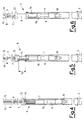
- Figure 1 is a partly sectional partial side view showing the insertion of a foundation pile into a relative guide in an offshore structure by means of a lifting and hammering device formed in accordance with the present invention;
- Figure 2 is a view analogous to that of Figure 1 after the pile has been hammered by the device of the invention;
- Figure 3 is a partly sectional perspective view of the lifting and hammering device of Figure 1 to an enlarged scale;
- Figures 4, 5 and 6 are partly sectional partial perspective views showing the various operating stages of the lifting and hammering device according to the invention.
- With reference to the figures, 1 indicates a foundation pile which is to be inserted into the
appropriate guide 2 of theoffshore structure 3 and then driven into the sea bed 4 by hammering until a predetermined penetration is achieved. - This is done by using the lifting and
hammering device 5 of the invention, consisting of along support element 6 which has to be completely inserted into saidpile 1. Saidelement 6 is held suspended from a crane, not shown in the figures, situated on a pontoon for offshore work, also not shown in the figures, by asling 7 connected to thehook 8 of said crane and shackled at 9 to the lower end of the element, where it is provided with an expansion-type gripping clamp 10 operated hydraulically from said pontoon via ahose 11. At its other end thesupport element 6 comprises, rigid therewith, anelectromagnet 12 activated via thepower cable 13, to cooperate with the striking weight orhammer 14 slidable along saidsupport element 6 as far as alimit stop 15 provided on thesupport element 6. - The device operates in the following manner.
- After the lifting and
hammering device 5 has been completely inserted into thefoundation pile 1, its expansion-type gripping clamp 10 is hydraulically tightened against the inner wall of the pile while theenergized electromagnet 12 retains thehammer 14, which hence rests on the head of thepile 1. By this means thefoundation pile 1 can be lifted by the crane and positioned in therelative guide 2 of theoffshore structure 3 to be fixed to the sea bed 4 (see Figures 1 and 4 specifically). - At this point the
clamp 10 is disengaged and theentire device 5 is raised by said crane until alevel difference 16 is achieved (see Figure 5) which is equal to that falling distance for the striking weight orhammer 14 determined by design calculations, after which theelectromagnet 12 is de-energized so that the striking weight, no longer retained, collides against the head of thepile 1 to drive said pile into the sea bed 4 (see Figures 2 and 6). - The
support element 6 is then lowered until theelectromagnet 12 makes contact with thestriking weight 14, which is again rigidly retained by the electromagnet by energizing this latter, after which the described cycle is repeated.
Claims (3)
- A device (5) for lifting and positioning pipe-like foundation piles (1) for offshore structures (3) into a pile guide (2) provided in the offshore structure, and for hammering such piles into the sea bed (4), by means of a crane situated on a pontoon, said device comprising a striking weight or hammer (14), sliding along a guide element (6), to be inserted in the foundation pile, said guide element comprising at its lower end an expansion type gripping clamp (10) to be tightened during the transport and insertion of the pile (1) in the pile guide (2) of the offshore structure (3), characterised in that said device comprises:- a relatively long support element (6) compared with the length of the pile, forming said guide element, suspended from the crane by a sling (7), said support element being maintained freely sliding within the foundation pile with the expansion type gripping clamp (10) being maintained disengaged during the hammering operation;- the hammer (14) freely sliding along the outside of said support element (6), said hammer being of ferrous material;- an electromagnet (12) positioned on the upper part of the support element (6), and rigidly connected therewith, to be energised for magnetically engaging the hammer (14) on the upper part thereof and being movable together with said hammer during the lifting of the entire device (5) by the sling (7) connected to the crane, the electromagnet being de-energised when the hammer (14) is to be released to cause it to collide with the head of the pile (1);- a limit stop (15) on an intermediate part of element (6) for stopping said hammer (14) and absorbing the impact thereof.
- A device for hammering the foundation piles of offshore structures as claimed in claim 1, characterised in that the support element (6) further comprises a length in the order of twenty meters.
- Method for lifting and hammering foundation piles of an offshore structure with a device according to claim 1, characterised by comprising the following stages:- a) completely inserting the device (5) into the foundation pile (1);- b) tightening the gripping clamp (10) against the inner wall of the pile (1), while the energised electromagnet (12) retains the hammer (14);- c) lifting the pile (1) with the crane and positioning it in the pile guide (2) of the offshore structure (3);- d) disengaging the clamp (10);- e) raising the entire device (5) with the crane by a level difference corresponding to the desired falling distance (16) for the hammer (14);- f) de-energising the electromagnet (12) to cause the hammer to fall, so that it collides against the head of the pile (1);- g) lowering the support element (6) until the electromagnet (12) again makes contact with the hammer (14) which is again rigidly retained by energising the electromagnet (12);- h) repeating the stages e)-g) until the predetermined penetration of the foundation pile (1) is achieved.
Applications Claiming Priority (2)
| Application Number | Priority Date | Filing Date | Title |
|---|---|---|---|
| ITMI911793A IT1248590B (en) | 1991-06-28 | 1991-06-28 | IMPROVED DEVICE FOR LIFTING AND BATTING OF FOUNDATION POLES OF OFFSHORE STRUCTURES |
| ITMI911793 | 1991-06-28 |
Publications (2)
| Publication Number | Publication Date |
|---|---|
| EP0520544A1 EP0520544A1 (en) | 1992-12-30 |
| EP0520544B1 true EP0520544B1 (en) | 1995-08-09 |
Family
ID=11360232
Family Applications (1)
| Application Number | Title | Priority Date | Filing Date |
|---|---|---|---|
| EP92201713A Expired - Lifetime EP0520544B1 (en) | 1991-06-28 | 1992-06-12 | Improved device for lifting and hammering foundation piles for offshore structures |
Country Status (14)
| Country | Link |
|---|---|
| US (1) | US5257879A (en) |
| EP (1) | EP0520544B1 (en) |
| AT (1) | ATE126303T1 (en) |
| BR (1) | BR9202482A (en) |
| CA (1) | CA2071427C (en) |
| DE (1) | DE69203980T2 (en) |
| DK (1) | DK0520544T3 (en) |
| ES (1) | ES2076665T3 (en) |
| FI (1) | FI103525B1 (en) |
| GR (1) | GR3017228T3 (en) |
| IE (1) | IE69030B1 (en) |
| IT (1) | IT1248590B (en) |
| NO (1) | NO304528B1 (en) |
| NZ (1) | NZ243254A (en) |
Cited By (2)
| Publication number | Priority date | Publication date | Assignee | Title |
|---|---|---|---|---|
| AU2010241465B2 (en) * | 2009-11-17 | 2011-11-24 | Bauer Maschinen Gmbh | Underwater drilling arrangement and method for introducing a tubular foundation element into the bed of a body of water |
| US8517639B2 (en) | 2005-10-14 | 2013-08-27 | Tidal Generation Limited | Installation of underwater anchorages |
Families Citing this family (7)
| Publication number | Priority date | Publication date | Assignee | Title |
|---|---|---|---|---|
| FR2723975A1 (en) * | 1994-08-30 | 1996-03-01 | Technip Geoproduction | OIL PLATFORM FOR DRILLING OR EXPLOITATION AT SEA, PROVIDED WITH IMPROVED MEANS OF ANCHORING IN THE MARINE SOIL. |
| US6814524B1 (en) | 2001-10-02 | 2004-11-09 | James L. Peterson | Method and apparatus for lifting and stabilizing subsided slabs, flatwork and foundations of buildings |
| US7163357B1 (en) | 2001-10-02 | 2007-01-16 | Peterson James L | Method and apparatus for lifting and stabilizing subsided slabs, flatwork and foundations of buildings |
| NZ528332A (en) * | 2003-09-22 | 2006-04-28 | Ramet Holdings Ltd | Impact driver for driving poles, piles or posts including linear induction motor |
| NL2012858B1 (en) * | 2014-05-22 | 2016-03-15 | Ihc Holland Ie Bv | Tubular foundation element, assembly and method for installing tubular foundation elements in a ground formation. |
| US10941538B2 (en) * | 2018-04-13 | 2021-03-09 | Hohhot Sifang Engineering Quality Testing Center | Hammering system with electromagnetic power for dynamic pile testing |
| CN115030213B (en) * | 2022-05-26 | 2023-04-11 | 上海勘测设计研究院有限公司 | Tool suitable for offshore wind power foundation pile and application method |
Family Cites Families (7)
| Publication number | Priority date | Publication date | Assignee | Title |
|---|---|---|---|---|
| US3526283A (en) * | 1968-07-23 | 1970-09-01 | S O G Research & Dev Corp | Pile driver |
| US3680644A (en) * | 1970-12-28 | 1972-08-01 | Santa Fe Int Corp | Pile driving system and apparatus |
| US4257720A (en) * | 1979-01-15 | 1981-03-24 | Pipe Technology Systems, Inc. | Apparatus and method for driving members into the ocean floor |
| US4362439A (en) * | 1981-03-02 | 1982-12-07 | Vaynkof Peter P | Hydrostatically operated underwater pile driver and method of operating same |
| EP0265566B1 (en) * | 1986-10-24 | 1989-06-14 | Procedes Techniques De Construction | Electromagnetic percussion pile driver |
| FR2601397B1 (en) * | 1986-07-11 | 1989-07-28 | Technologies Speciales Ingenie | THRESHING METHOD AND DEVICE FOR PUSHING TOOLS INTO THE GROUND. |
| EP0301116B1 (en) * | 1987-07-28 | 1991-07-03 | Menck Gmbh | Submergible electrohydraulic drive unit for hammering and servicing devices in under water operation |
-
1991
- 1991-06-28 IT ITMI911793A patent/IT1248590B/en active IP Right Grant
-
1992
- 1992-06-12 ES ES92201713T patent/ES2076665T3/en not_active Expired - Lifetime
- 1992-06-12 DK DK92201713.2T patent/DK0520544T3/en active
- 1992-06-12 AT AT92201713T patent/ATE126303T1/en not_active IP Right Cessation
- 1992-06-12 DE DE69203980T patent/DE69203980T2/en not_active Expired - Fee Related
- 1992-06-12 EP EP92201713A patent/EP0520544B1/en not_active Expired - Lifetime
- 1992-06-15 US US07/898,470 patent/US5257879A/en not_active Expired - Fee Related
- 1992-06-17 CA CA002071427A patent/CA2071427C/en not_active Expired - Fee Related
- 1992-06-17 NO NO922371A patent/NO304528B1/en not_active IP Right Cessation
- 1992-06-22 NZ NZ243254A patent/NZ243254A/en unknown
- 1992-06-25 FI FI922948A patent/FI103525B1/en active
- 1992-07-01 IE IE922084A patent/IE69030B1/en not_active IP Right Cessation
- 1992-07-07 BR BR929202482A patent/BR9202482A/en not_active IP Right Cessation
-
1995
- 1995-08-30 GR GR950402336T patent/GR3017228T3/en unknown
Cited By (2)
| Publication number | Priority date | Publication date | Assignee | Title |
|---|---|---|---|---|
| US8517639B2 (en) | 2005-10-14 | 2013-08-27 | Tidal Generation Limited | Installation of underwater anchorages |
| AU2010241465B2 (en) * | 2009-11-17 | 2011-11-24 | Bauer Maschinen Gmbh | Underwater drilling arrangement and method for introducing a tubular foundation element into the bed of a body of water |
Also Published As
| Publication number | Publication date |
|---|---|
| NO922371D0 (en) | 1992-06-17 |
| IE922084A1 (en) | 1992-12-30 |
| NZ243254A (en) | 1994-10-26 |
| US5257879A (en) | 1993-11-02 |
| FI922948A0 (en) | 1992-06-25 |
| NO922371L (en) | 1992-12-29 |
| EP0520544A1 (en) | 1992-12-30 |
| DE69203980T2 (en) | 1996-02-15 |
| DE69203980D1 (en) | 1995-09-14 |
| CA2071427A1 (en) | 1992-12-29 |
| IT1248590B (en) | 1995-01-19 |
| CA2071427C (en) | 2000-02-15 |
| ATE126303T1 (en) | 1995-08-15 |
| NO304528B1 (en) | 1999-01-04 |
| FI103525B (en) | 1999-07-15 |
| BR9202482A (en) | 1993-02-09 |
| FI103525B1 (en) | 1999-07-15 |
| ITMI911793A1 (en) | 1992-12-28 |
| FI922948L (en) | 1992-12-29 |
| GR3017228T3 (en) | 1995-11-30 |
| ES2076665T3 (en) | 1995-11-01 |
| IE69030B1 (en) | 1996-08-07 |
| DK0520544T3 (en) | 1995-11-13 |
| ITMI911793A0 (en) | 1991-06-28 |
Similar Documents
| Publication | Publication Date | Title |
|---|---|---|
| US5205673A (en) | Foundation slab support and lifting apparatus | |
| IE69030B1 (en) | Improved device for lifting and hammering foundation piles for offshore structures | |
| US4154307A (en) | Pile driving system | |
| CN108571005B (en) | Jacket construction process | |
| US5332047A (en) | Pile driving apparatus and method | |
| NZ528332A (en) | Impact driver for driving poles, piles or posts including linear induction motor | |
| US3847231A (en) | Pole reinforcement installation | |
| JP6826801B2 (en) | Fishing reefs and how to set up fishing reefs | |
| CN211979216U (en) | An artificial seismic source device for geophysical exploration | |
| KR102727532B1 (en) | A hammer for a pile driver operated by a solenoid structure | |
| USRE28151E (en) | Tube driving apparatus | |
| JPH06346441A (en) | Method for driving pile using hull and device thereof | |
| JPH11200358A (en) | Method and device for creating sand pile | |
| CN219098486U (en) | Lifting appliance convenient for coiled material feeding | |
| CN217500201U (en) | Hammering steel pipe pile construction system | |
| US20260132586A1 (en) | Pile lifting device | |
| CN116104084A (en) | Channel steel construction device | |
| KR20230055755A (en) | Pile Driver for Marine Enviroment | |
| JP3683936B2 (en) | Steel pipe pile hammering method and equipment | |
| JPS57174535A (en) | Pile driving work | |
| RU1796742C (en) | Device for making vertical holes | |
| JPH073055B2 (en) | Underwater pile driving hammer and underwater pile driving method | |
| AU2009274628B2 (en) | System and method for driving pile under water | |
| JP2004044199A (en) | Construction method for jacket structure and level adjusting apparatus | |
| EP4709935A1 (en) | Pile driving system |
Legal Events
| Date | Code | Title | Description |
|---|---|---|---|
| PUAI | Public reference made under article 153(3) epc to a published international application that has entered the european phase |
Free format text: ORIGINAL CODE: 0009012 |
|
| AK | Designated contracting states |
Kind code of ref document: A1 Designated state(s): AT BE DE DK ES FR GB GR LU NL PT SE |
|
| 17P | Request for examination filed |
Effective date: 19930120 |
|
| 17Q | First examination report despatched |
Effective date: 19931214 |
|
| GRAA | (expected) grant |
Free format text: ORIGINAL CODE: 0009210 |
|
| AK | Designated contracting states |
Kind code of ref document: B1 Designated state(s): AT BE DE DK ES FR GB GR LU NL PT SE |
|
| REF | Corresponds to: |
Ref document number: 126303 Country of ref document: AT Date of ref document: 19950815 Kind code of ref document: T |
|
| REF | Corresponds to: |
Ref document number: 69203980 Country of ref document: DE Date of ref document: 19950914 |
|
| ET | Fr: translation filed | ||
| REG | Reference to a national code |
Ref country code: GR Ref legal event code: FG4A Free format text: 3017228 |
|
| REG | Reference to a national code |
Ref country code: ES Ref legal event code: FG2A Ref document number: 2076665 Country of ref document: ES Kind code of ref document: T3 |
|
| REG | Reference to a national code |
Ref country code: DK Ref legal event code: T3 |
|
| PLBE | No opposition filed within time limit |
Free format text: ORIGINAL CODE: 0009261 |
|
| STAA | Information on the status of an ep patent application or granted ep patent |
Free format text: STATUS: NO OPPOSITION FILED WITHIN TIME LIMIT |
|
| 26N | No opposition filed | ||
| REG | Reference to a national code |
Ref country code: GB Ref legal event code: IF02 |
|
| PGFP | Annual fee paid to national office [announced via postgrant information from national office to epo] |
Ref country code: PT Payment date: 20020529 Year of fee payment: 11 |
|
| PGFP | Annual fee paid to national office [announced via postgrant information from national office to epo] |
Ref country code: SE Payment date: 20020611 Year of fee payment: 11 |
|
| PGFP | Annual fee paid to national office [announced via postgrant information from national office to epo] |
Ref country code: AT Payment date: 20020612 Year of fee payment: 11 |
|
| PGFP | Annual fee paid to national office [announced via postgrant information from national office to epo] |
Ref country code: LU Payment date: 20020620 Year of fee payment: 11 |
|
| PGFP | Annual fee paid to national office [announced via postgrant information from national office to epo] |
Ref country code: GR Payment date: 20020626 Year of fee payment: 11 |
|
| PGFP | Annual fee paid to national office [announced via postgrant information from national office to epo] |
Ref country code: BE Payment date: 20020827 Year of fee payment: 11 |
|
| PGFP | Annual fee paid to national office [announced via postgrant information from national office to epo] |
Ref country code: FR Payment date: 20030610 Year of fee payment: 12 |
|
| PGFP | Annual fee paid to national office [announced via postgrant information from national office to epo] |
Ref country code: GB Payment date: 20030611 Year of fee payment: 12 |
|
| PG25 | Lapsed in a contracting state [announced via postgrant information from national office to epo] |
Ref country code: LU Free format text: LAPSE BECAUSE OF NON-PAYMENT OF DUE FEES Effective date: 20030612 Ref country code: AT Free format text: LAPSE BECAUSE OF NON-PAYMENT OF DUE FEES Effective date: 20030612 |
|
| PG25 | Lapsed in a contracting state [announced via postgrant information from national office to epo] |
Ref country code: SE Free format text: LAPSE BECAUSE OF NON-PAYMENT OF DUE FEES Effective date: 20030613 |
|
| PGFP | Annual fee paid to national office [announced via postgrant information from national office to epo] |
Ref country code: DK Payment date: 20030613 Year of fee payment: 12 |
|
| PGFP | Annual fee paid to national office [announced via postgrant information from national office to epo] |
Ref country code: DE Payment date: 20030618 Year of fee payment: 12 |
|
| PGFP | Annual fee paid to national office [announced via postgrant information from national office to epo] |
Ref country code: ES Payment date: 20030619 Year of fee payment: 12 |
|
| PG25 | Lapsed in a contracting state [announced via postgrant information from national office to epo] |
Ref country code: BE Free format text: LAPSE BECAUSE OF NON-PAYMENT OF DUE FEES Effective date: 20030630 |
|
| PGFP | Annual fee paid to national office [announced via postgrant information from national office to epo] |
Ref country code: NL Payment date: 20030630 Year of fee payment: 12 |
|
| BERE | Be: lapsed |
Owner name: *SAIPEM S.P.A. Effective date: 20030630 |
|
| PG25 | Lapsed in a contracting state [announced via postgrant information from national office to epo] |
Ref country code: PT Free format text: LAPSE BECAUSE OF NON-PAYMENT OF DUE FEES Effective date: 20031231 |
|
| PG25 | Lapsed in a contracting state [announced via postgrant information from national office to epo] |
Ref country code: GR Free format text: LAPSE BECAUSE OF NON-PAYMENT OF DUE FEES Effective date: 20040107 |
|
| EUG | Se: european patent has lapsed | ||
| REG | Reference to a national code |
Ref country code: PT Ref legal event code: MM4A Free format text: LAPSE DUE TO NON-PAYMENT OF FEES Effective date: 20031231 |
|
| PG25 | Lapsed in a contracting state [announced via postgrant information from national office to epo] |
Ref country code: GB Free format text: LAPSE BECAUSE OF NON-PAYMENT OF DUE FEES Effective date: 20040612 |
|
| PG25 | Lapsed in a contracting state [announced via postgrant information from national office to epo] |
Ref country code: ES Free format text: LAPSE BECAUSE OF NON-PAYMENT OF DUE FEES Effective date: 20040614 |
|
| PG25 | Lapsed in a contracting state [announced via postgrant information from national office to epo] |
Ref country code: DK Free format text: LAPSE BECAUSE OF NON-PAYMENT OF DUE FEES Effective date: 20040630 |
|
| PG25 | Lapsed in a contracting state [announced via postgrant information from national office to epo] |
Ref country code: NL Free format text: LAPSE BECAUSE OF NON-PAYMENT OF DUE FEES Effective date: 20050101 Ref country code: DE Free format text: LAPSE BECAUSE OF NON-PAYMENT OF DUE FEES Effective date: 20050101 |
|
| REG | Reference to a national code |
Ref country code: DK Ref legal event code: EBP |
|
| GBPC | Gb: european patent ceased through non-payment of renewal fee |
Effective date: 20040612 |
|
| PG25 | Lapsed in a contracting state [announced via postgrant information from national office to epo] |
Ref country code: FR Free format text: LAPSE BECAUSE OF NON-PAYMENT OF DUE FEES Effective date: 20050228 |
|
| NLV4 | Nl: lapsed or anulled due to non-payment of the annual fee |
Effective date: 20050101 |
|
| REG | Reference to a national code |
Ref country code: FR Ref legal event code: ST |
|
| REG | Reference to a national code |
Ref country code: ES Ref legal event code: FD2A Effective date: 20040614 |