EP0520538A1 - Hochdruckentladungslampe - Google Patents
Hochdruckentladungslampe Download PDFInfo
- Publication number
- EP0520538A1 EP0520538A1 EP92201627A EP92201627A EP0520538A1 EP 0520538 A1 EP0520538 A1 EP 0520538A1 EP 92201627 A EP92201627 A EP 92201627A EP 92201627 A EP92201627 A EP 92201627A EP 0520538 A1 EP0520538 A1 EP 0520538A1
- Authority
- EP
- European Patent Office
- Prior art keywords
- lamp
- sidac
- capsule
- outer bulb
- gas
- Prior art date
- Legal status (The legal status is an assumption and is not a legal conclusion. Google has not performed a legal analysis and makes no representation as to the accuracy of the status listed.)
- Granted
Links
- 239000002775 capsule Substances 0.000 claims abstract description 18
- 239000003990 capacitor Substances 0.000 claims description 14
- 230000001419 dependent effect Effects 0.000 claims description 9
- 239000011521 glass Substances 0.000 abstract description 6
- 239000007789 gas Substances 0.000 description 15
- 239000003381 stabilizer Substances 0.000 description 6
- 238000004519 manufacturing process Methods 0.000 description 5
- 230000008901 benefit Effects 0.000 description 4
- QSHDDOUJBYECFT-UHFFFAOYSA-N mercury Chemical compound [Hg] QSHDDOUJBYECFT-UHFFFAOYSA-N 0.000 description 4
- 229910052753 mercury Inorganic materials 0.000 description 4
- 239000004020 conductor Substances 0.000 description 3
- 230000008020 evaporation Effects 0.000 description 3
- 238000001704 evaporation Methods 0.000 description 3
- IJGRMHOSHXDMSA-UHFFFAOYSA-N Atomic nitrogen Chemical compound N#N IJGRMHOSHXDMSA-UHFFFAOYSA-N 0.000 description 2
- DGAQECJNVWCQMB-PUAWFVPOSA-M Ilexoside XXIX Chemical compound C[C@@H]1CC[C@@]2(CC[C@@]3(C(=CC[C@H]4[C@]3(CC[C@@H]5[C@@]4(CC[C@@H](C5(C)C)OS(=O)(=O)[O-])C)C)[C@@H]2[C@]1(C)O)C)C(=O)O[C@H]6[C@@H]([C@H]([C@@H]([C@H](O6)CO)O)O)O.[Na+] DGAQECJNVWCQMB-PUAWFVPOSA-M 0.000 description 2
- 238000010276 construction Methods 0.000 description 2
- 238000010494 dissociation reaction Methods 0.000 description 2
- 230000005593 dissociations Effects 0.000 description 2
- 230000004907 flux Effects 0.000 description 2
- 238000010438 heat treatment Methods 0.000 description 2
- 230000006872 improvement Effects 0.000 description 2
- 230000009467 reduction Effects 0.000 description 2
- 229910052708 sodium Inorganic materials 0.000 description 2
- 239000011734 sodium Substances 0.000 description 2
- 229910018503 SF6 Inorganic materials 0.000 description 1
- 230000009471 action Effects 0.000 description 1
- QVGXLLKOCUKJST-UHFFFAOYSA-N atomic oxygen Chemical compound [O] QVGXLLKOCUKJST-UHFFFAOYSA-N 0.000 description 1
- 238000006243 chemical reaction Methods 0.000 description 1
- 238000010586 diagram Methods 0.000 description 1
- 230000020169 heat generation Effects 0.000 description 1
- 238000009434 installation Methods 0.000 description 1
- 230000008018 melting Effects 0.000 description 1
- 238000002844 melting Methods 0.000 description 1
- 238000000034 method Methods 0.000 description 1
- 239000000203 mixture Substances 0.000 description 1
- 229910052757 nitrogen Inorganic materials 0.000 description 1
- 239000001301 oxygen Substances 0.000 description 1
- 229910052760 oxygen Inorganic materials 0.000 description 1
- SFZCNBIFKDRMGX-UHFFFAOYSA-N sulfur hexafluoride Chemical compound FS(F)(F)(F)(F)F SFZCNBIFKDRMGX-UHFFFAOYSA-N 0.000 description 1
- 229910052724 xenon Inorganic materials 0.000 description 1
- FHNFHKCVQCLJFQ-UHFFFAOYSA-N xenon atom Chemical compound [Xe] FHNFHKCVQCLJFQ-UHFFFAOYSA-N 0.000 description 1
Images
Classifications
-
- H—ELECTRICITY
- H01—ELECTRIC ELEMENTS
- H01J—ELECTRIC DISCHARGE TUBES OR DISCHARGE LAMPS
- H01J61/00—Gas-discharge or vapour-discharge lamps
- H01J61/02—Details
- H01J61/54—Igniting arrangements, e.g. promoting ionisation for starting
-
- H—ELECTRICITY
- H05—ELECTRIC TECHNIQUES NOT OTHERWISE PROVIDED FOR
- H05B—ELECTRIC HEATING; ELECTRIC LIGHT SOURCES NOT OTHERWISE PROVIDED FOR; CIRCUIT ARRANGEMENTS FOR ELECTRIC LIGHT SOURCES, IN GENERAL
- H05B41/00—Circuit arrangements or apparatus for igniting or operating discharge lamps
- H05B41/02—Details
- H05B41/04—Starting switches
- H05B41/042—Starting switches using semiconductor devices
-
- H—ELECTRICITY
- H05—ELECTRIC TECHNIQUES NOT OTHERWISE PROVIDED FOR
- H05B—ELECTRIC HEATING; ELECTRIC LIGHT SOURCES NOT OTHERWISE PROVIDED FOR; CIRCUIT ARRANGEMENTS FOR ELECTRIC LIGHT SOURCES, IN GENERAL
- H05B41/00—Circuit arrangements or apparatus for igniting or operating discharge lamps
- H05B41/14—Circuit arrangements
- H05B41/16—Circuit arrangements in which the lamp is fed by dc or by low-frequency ac, e.g. by 50 cycles/sec ac, or with network frequencies
- H05B41/18—Circuit arrangements in which the lamp is fed by dc or by low-frequency ac, e.g. by 50 cycles/sec ac, or with network frequencies having a starting switch
- H05B41/19—Circuit arrangements in which the lamp is fed by dc or by low-frequency ac, e.g. by 50 cycles/sec ac, or with network frequencies having a starting switch for lamps having an auxiliary starting electrode
Definitions
- the invention relates to a high-pressure discharge lamp provided with a discharge vessel, which vessel is enclosed with intervening space by an outer bulb and fitted with a lamp cap, and provided with an ignition circuit comprising a SIDAC.
- a lamp of the kind mentioned in the opening paragraph is known from US-P 4 520 294.
- the SIDAC is positioned in the outer bulb and provided with a glass envelope as a protection against reduction and evaporation of parts of the SIDAC.
- Practice has shown, however, that this involves major disadvantages.
- the manufacture of a SIDAC provided with such an envelope is very difficult, which renders the SIDAC very expensive.
- the known lamp is found to show a high percentage of early failures owing to blackening of the discharge vessel.
- the invention has for its object to provide a measure by which the described disadvantages are counteracted, while a comparatively simple lamp manufacturing method is maintained.
- this object is realized in a lamp of the kind mentioned in the opening paragraph in that the lamp is characterized in that the SIDAC is mounted in a gas-filled space in the outer bulb.
- the gas-filled space may be the entire space enclosed between the outer bulb and the discharge vessel.
- a construction whereby the SIDAC is accommodated in a hermetically closed capsule is a construction whereby the SIDAC is accommodated in a hermetically closed capsule.
- a glass capsule is preferably used as the hermetically closed capsule.
- An advantage is that the SIDAC is accommodated in a glass capsule by means of a technique which has long been known and proved effective, so that production is simple and reliable, leading to cost reduction in comparison with the known lamp.
- the pressure of the gas then ensures that dissociation and/or evaporation of components from which the SIDAC is built up is counteracted.
- Gas composition is so chosen that no reactions with components of the SIDAC take place under the prevalent conditions during lamp operation.
- gases are rare gases, nitrogen and oxygen, and SF6.
- the gas filling may be formed by a single gas, but combinations of gases are also possible. As was stated above, it is conceivable to fill the outer bulb itself with a suitable gas instead of using a separate capsule.
- a further advantage of the invention is that the use of the hermetically closed, gas-filled capsule for mounting the SIDAC means that the measure according to the invention is generally applicable in high-pressure discharge lamps.
- a further improvement of the lamp can be achieved in that the capsule is provided with a radiation-reflecting layer. It is achieved in a simple but effective manner by this that heating of the SIDAC in the operational state of the lamp is considerably reduced.
- the radiation-reflecting layer may be provided either externally or internally.
- the ignition circuit also includes a voltage-dependent capacitor, this capacitor is preferably mounted together with the SIDAC in the capsule. Preferably, the voltage-dependent capacitor is so positioned that the longitudinal axis of the discharge vessel lies substantially in a common plane with the capacitor, which is usually disc-shaped. Irradiation of the capacitor is minimized by this.
- the use of a SIDAC in combination with a voltage-dependent capacitor renders the generation of very high voltage pulses possible.
- the hermetically closed capsule it is preferable for the hermetically closed capsule to be filled with SF6 at a pressure of at least 0,5 atmosphere.
- the ignition circuit is also provided with a fuse. It is achieved by this that even under unfavourable conditions, such as short-circuiting of the capacitor, an overload of the stabilizer ballast through excessive currents is prevented by melting of the fuse.
- the fuse may be included in the capsule.
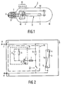
- FIG. 1 shows a lamp 2 according to the invention provided with a discharge vessel 3, which is enclosed with intervening space by an outer bulb 30 fitted with a lamp cap 31, and provided with an ignition circuit 10 comprising a SIDAC 6.
- the SIDAC 6 is mounted in a hermetically closed, gas-filled glass capsule 11.
- the discharge vessel 3 is provided with lamp electrodes 4 and 5 between which a discharge takes place in the operational state of the lamp.
- Lamp electrode 4 is connected to a lamp connection point C of lamp cap 31 via a rigid current conductor 40.
- lamp electrode 5 is connected to a lamp connection point D of lamp cap 31 via a rigid current conductor 50.
- the starting circuit 10 is also provided with a fuse 7 and a voltage-dependent capacitor 8.
- the voltage-dependent capacitor 8 in this case is mounted in the capsule 11 together with the SIDAC 6.
- a and B are connection points for connecting an AC voltage supply source.
- Connection point A is connected to lamp connection point C via a stabilizer ballast 1.
- Connection point B is connected to lamp connection point D.
- the ignition circuit 10 formed by the chain comprising SIDAC 6, fuse 7, voltage-dependent capacitor 8, resistors 9 and 12, and a bimetal switch 13 in conjunction with stabilizer ballast 1 generates in known manner ignition pulses between the lamp connection points C and D, and thus between the lamp electrodes 4 and 5.
- the discharge vessel 3 may be provided with an external auxiliary electrode 5a as a further ignition aid.
- the bimetal switch 13 is closed in the non-ignited state of the lamp and is open in the operational state of the lamp owing to the heat generation in this operational state.
- the bimetal switch is so constructed that it also ensures that the electrical contact between auxiliary electrode 5a and lamp electrode 5 is broken in the operational state of the lamp.
- the auxiliary electrode 5a is substantially bent away from the discharge vessel 3 in the open state of the bimetal switch 13 owing to the action of this bimetal switch.
- the resistors 9 and 12 serve to ensure that the voltage-dependent capacitor can always discharge, also in the case of an open bimetal switch 13.
- the resistor 9 serves to increase the reproducibility of the moment an ignition pulse is generated in relation to the instantaneous value of the supply voltage.
- the lamp was a high-pressure sodium discharge lamp with a power rating of 150 W.
- the discharge vessel contained xenon with a pressure of 27 kPa at 300 K in addition to sodium and mercury.
- the lamp was operated on a supply voltage source of 120 V, 60 Hz through a mercury - CWA 175 W - stabilizer ballast, type 71A3002, make Advance Transformer.
- the discharge vessel was provided with an external auxiliary electrode.
- the ignition circuit was formed by a type K1-V-15I SIDAC, make Shindengen, which was mounted in a gas-filled gastight glass capsule together with a voltage-dependent capacitor, make TDK.
- the disc-shaped capacitor was at a distance of approximately 20 mm from the adjacent end of the discharge vessel and was substantially in one common plane with the longitudinal axis of the discharge vessel.
- the gas filling was formed by SF6 which had a pressure of 0,5 at at room temperature.
- the ignition circuit Upon connection to the 120 V, 60 Hz supply source, the ignition circuit generated an ignition voltage pulse of approximately 2,5 kV approximately 1 ms after each zero passage of the supply voltage.
- the lamp ignited quickly and reliably on this.
- the lamp was thus found to be suitable for operation in a usual installation for a high-pressure mercury lamp, and thus to serve as a replacement for a 175 W high-pressure mercury lamp.
Landscapes
- Discharge Lamps And Accessories Thereof (AREA)
- Circuit Arrangements For Discharge Lamps (AREA)
Applications Claiming Priority (2)
| Application Number | Priority Date | Filing Date | Title |
|---|---|---|---|
| EP91201437 | 1991-06-12 | ||
| EP91201437 | 1991-06-12 |
Publications (2)
| Publication Number | Publication Date |
|---|---|
| EP0520538A1 true EP0520538A1 (de) | 1992-12-30 |
| EP0520538B1 EP0520538B1 (de) | 1997-01-22 |
Family
ID=8207709
Family Applications (1)
| Application Number | Title | Priority Date | Filing Date |
|---|---|---|---|
| EP92201627A Expired - Lifetime EP0520538B1 (de) | 1991-06-12 | 1992-06-05 | Hochdruckentladungslampe |
Country Status (5)
| Country | Link |
|---|---|
| US (1) | US5185557A (de) |
| EP (1) | EP0520538B1 (de) |
| JP (1) | JP3356797B2 (de) |
| CA (1) | CA2070845A1 (de) |
| DE (1) | DE69216916T2 (de) |
Families Citing this family (4)
| Publication number | Priority date | Publication date | Assignee | Title |
|---|---|---|---|---|
| US5339006A (en) * | 1992-03-13 | 1994-08-16 | U.S. Philips Corporation | High pressure discharge lamp |
| US5606222A (en) * | 1994-12-29 | 1997-02-25 | Philips Electronics North America Corporation | Lighting system with a device for reducing system wattage |
| DE19923237A1 (de) | 1999-05-20 | 2000-11-23 | Patent Treuhand Ges Fuer Elektrische Gluehlampen Mbh | Schaltungsanordnung, zugeordnetes elektrisches System sowie Entladungslampe mit derartiger Schaltungsanordnung und Verfahren zu ihrem Betrieb |
| DE102007026317A1 (de) * | 2007-06-06 | 2008-12-11 | Osram Gesellschaft mit beschränkter Haftung | Hochdruckentladungslampe mit verbesserter Zündvorrichtung sowie Zündvorrichtung für eine Gasentladungslampe |
Citations (2)
| Publication number | Priority date | Publication date | Assignee | Title |
|---|---|---|---|---|
| DE1589162B2 (de) * | 1966-01-12 | 1975-04-30 | The General Electric Co. Ltd., London | Elektrische Hochdruck-Metalldampfentladungslampe |
| US4520294A (en) * | 1982-08-23 | 1985-05-28 | Iwasaki Electric Co., Ltd. | High pressure metal vapor discharge lamp |
Family Cites Families (2)
| Publication number | Priority date | Publication date | Assignee | Title |
|---|---|---|---|---|
| HU195381B (en) * | 1986-04-02 | 1988-04-28 | Tungsram Reszvenytarsasag | Electronic firing unit for high-pressure discharge lamps |
| US4950961A (en) * | 1986-11-28 | 1990-08-21 | Gte Products Corporation | Starting circuit for gaseous discharge lamps |
-
1992
- 1992-01-22 US US07/823,927 patent/US5185557A/en not_active Expired - Fee Related
- 1992-06-05 DE DE69216916T patent/DE69216916T2/de not_active Expired - Fee Related
- 1992-06-05 EP EP92201627A patent/EP0520538B1/de not_active Expired - Lifetime
- 1992-06-09 CA CA002070845A patent/CA2070845A1/en not_active Abandoned
- 1992-06-10 JP JP15060792A patent/JP3356797B2/ja not_active Expired - Fee Related
Patent Citations (2)
| Publication number | Priority date | Publication date | Assignee | Title |
|---|---|---|---|---|
| DE1589162B2 (de) * | 1966-01-12 | 1975-04-30 | The General Electric Co. Ltd., London | Elektrische Hochdruck-Metalldampfentladungslampe |
| US4520294A (en) * | 1982-08-23 | 1985-05-28 | Iwasaki Electric Co., Ltd. | High pressure metal vapor discharge lamp |
Also Published As
| Publication number | Publication date |
|---|---|
| JPH05159748A (ja) | 1993-06-25 |
| JP3356797B2 (ja) | 2002-12-16 |
| US5185557A (en) | 1993-02-09 |
| DE69216916T2 (de) | 1997-07-17 |
| EP0520538B1 (de) | 1997-01-22 |
| CA2070845A1 (en) | 1992-12-13 |
| DE69216916D1 (de) | 1997-03-06 |
Similar Documents
| Publication | Publication Date | Title |
|---|---|---|
| US5955845A (en) | High pressure series arc discharge lamp construction with simplified starting aid | |
| CA1107344A (en) | Hid sodium lamp which incorporates a high pressure of xenon and a trigger starting electrode | |
| CA1154076A (en) | High intensity discharge lamp containing electronic starting aid | |
| US3849691A (en) | High intensity lamp containing arc extinguishing base | |
| EP0550928B1 (de) | Hochdruckentladungslampe | |
| US3828214A (en) | Plasma enshrouded electric discharge device | |
| US3767965A (en) | High intensity lamp containing internal shorting fuse | |
| EP0062381B1 (de) | Hochdruckentladungslampe | |
| EP0520538B1 (de) | Hochdruckentladungslampe | |
| US3737717A (en) | High intensity lamp containing thermal shorting fuse | |
| EP0431696B1 (de) | Hochdruckentladungslampe | |
| US3757159A (en) | Sodium vapor lamp having improved starting means | |
| HU218819B (hu) | Fénycső kiégési ívkioltó szerkezettel | |
| US5339006A (en) | High pressure discharge lamp | |
| JPS61109254A (ja) | 低ワツト数のメタルハライド放電ランプ | |
| EP0554925B1 (de) | Hochdruckentladungslampe | |
| US4686421A (en) | Glow discharge starter and arc discharge lamp containing same | |
| EP0085487B1 (de) | Entladungslampen | |
| US3755708A (en) | Sodium vapor lamps having improved starting means | |
| EP0517304A2 (de) | Hochdruckgasentladungslampe | |
| US4362969A (en) | High intensity discharge lamp including arc extinguishing means | |
| US3909660A (en) | Metal halide discharge lamp starting electrode | |
| EP0431695B1 (de) | Hochdruckentladungslampe | |
| JP2001155879A (ja) | 高圧放電ランプ、高圧放電ランプ点灯装置および照明装置 | |
| JPS59198652A (ja) | 金属蒸気放電灯 |
Legal Events
| Date | Code | Title | Description |
|---|---|---|---|
| PUAI | Public reference made under article 153(3) epc to a published international application that has entered the european phase |
Free format text: ORIGINAL CODE: 0009012 |
|
| AK | Designated contracting states |
Kind code of ref document: A1 Designated state(s): BE DE FR GB IT NL |
|
| 17P | Request for examination filed |
Effective date: 19930618 |
|
| 17Q | First examination report despatched |
Effective date: 19950704 |
|
| GRAG | Despatch of communication of intention to grant |
Free format text: ORIGINAL CODE: EPIDOS AGRA |
|
| GRAH | Despatch of communication of intention to grant a patent |
Free format text: ORIGINAL CODE: EPIDOS IGRA |
|
| GRAH | Despatch of communication of intention to grant a patent |
Free format text: ORIGINAL CODE: EPIDOS IGRA |
|
| GRAA | (expected) grant |
Free format text: ORIGINAL CODE: 0009210 |
|
| STAA | Information on the status of an ep patent application or granted ep patent |
Free format text: STATUS: THE PATENT HAS BEEN GRANTED |
|
| AK | Designated contracting states |
Kind code of ref document: B1 Designated state(s): BE DE FR GB IT NL |
|
| PG25 | Lapsed in a contracting state [announced via postgrant information from national office to epo] |
Ref country code: NL Free format text: LAPSE BECAUSE OF FAILURE TO SUBMIT A TRANSLATION OF THE DESCRIPTION OR TO PAY THE FEE WITHIN THE PRESCRIBED TIME-LIMIT Effective date: 19970122 |
|
| REF | Corresponds to: |
Ref document number: 69216916 Country of ref document: DE Date of ref document: 19970306 |
|
| ITF | It: translation for a ep patent filed | ||
| ET | Fr: translation filed | ||
| NLV1 | Nl: lapsed or annulled due to failure to fulfill the requirements of art. 29p and 29m of the patents act | ||
| PLBE | No opposition filed within time limit |
Free format text: ORIGINAL CODE: 0009261 |
|
| 26N | No opposition filed | ||
| REG | Reference to a national code |
Ref country code: FR Ref legal event code: CD |
|
| REG | Reference to a national code |
Ref country code: GB Ref legal event code: IF02 |
|
| PGFP | Annual fee paid to national office [announced via postgrant information from national office to epo] |
Ref country code: FR Payment date: 20020625 Year of fee payment: 11 |
|
| PGFP | Annual fee paid to national office [announced via postgrant information from national office to epo] |
Ref country code: GB Payment date: 20020628 Year of fee payment: 11 |
|
| PGFP | Annual fee paid to national office [announced via postgrant information from national office to epo] |
Ref country code: BE Payment date: 20020726 Year of fee payment: 11 |
|
| PGFP | Annual fee paid to national office [announced via postgrant information from national office to epo] |
Ref country code: DE Payment date: 20020821 Year of fee payment: 11 |
|
| REG | Reference to a national code |
Ref country code: FR Ref legal event code: D6 |
|
| REG | Reference to a national code |
Ref country code: GB Ref legal event code: 746 Effective date: 20021111 |
|
| PG25 | Lapsed in a contracting state [announced via postgrant information from national office to epo] |
Ref country code: GB Free format text: LAPSE BECAUSE OF NON-PAYMENT OF DUE FEES Effective date: 20030605 |
|
| PG25 | Lapsed in a contracting state [announced via postgrant information from national office to epo] |
Ref country code: BE Free format text: LAPSE BECAUSE OF NON-PAYMENT OF DUE FEES Effective date: 20030630 |
|
| BERE | Be: lapsed |
Owner name: *KONINKLIJKE PHILIPS ELECTRONICS N.V. Effective date: 20030630 |
|
| PG25 | Lapsed in a contracting state [announced via postgrant information from national office to epo] |
Ref country code: DE Free format text: LAPSE BECAUSE OF NON-PAYMENT OF DUE FEES Effective date: 20040101 |
|
| GBPC | Gb: european patent ceased through non-payment of renewal fee |
Effective date: 20030605 |
|
| PG25 | Lapsed in a contracting state [announced via postgrant information from national office to epo] |
Ref country code: FR Free format text: LAPSE BECAUSE OF NON-PAYMENT OF DUE FEES Effective date: 20040227 |
|
| REG | Reference to a national code |
Ref country code: FR Ref legal event code: ST |
|
| PG25 | Lapsed in a contracting state [announced via postgrant information from national office to epo] |
Ref country code: IT Free format text: LAPSE BECAUSE OF NON-PAYMENT OF DUE FEES;WARNING: LAPSES OF ITALIAN PATENTS WITH EFFECTIVE DATE BEFORE 2007 MAY HAVE OCCURRED AT ANY TIME BEFORE 2007. THE CORRECT EFFECTIVE DATE MAY BE DIFFERENT FROM THE ONE RECORDED. Effective date: 20050605 |