EP0520501A2 - Compact N-way waveguide power divider - Google Patents
Compact N-way waveguide power divider Download PDFInfo
- Publication number
- EP0520501A2 EP0520501A2 EP92110851A EP92110851A EP0520501A2 EP 0520501 A2 EP0520501 A2 EP 0520501A2 EP 92110851 A EP92110851 A EP 92110851A EP 92110851 A EP92110851 A EP 92110851A EP 0520501 A2 EP0520501 A2 EP 0520501A2
- Authority
- EP
- European Patent Office
- Prior art keywords
- power divider
- waveguide
- pair
- waveguide sections
- coupling
- Prior art date
- Legal status (The legal status is an assumption and is not a legal conclusion. Google has not performed a legal analysis and makes no representation as to the accuracy of the status listed.)
- Withdrawn
Links
Images

Classifications
-
- H—ELECTRICITY
- H01—ELECTRIC ELEMENTS
- H01P—WAVEGUIDES; RESONATORS, LINES, OR OTHER DEVICES OF THE WAVEGUIDE TYPE
- H01P1/00—Auxiliary devices
- H01P1/32—Non-reciprocal transmission devices
- H01P1/36—Isolators
- H01P1/37—Field displacement isolators
-
- H—ELECTRICITY
- H01—ELECTRIC ELEMENTS
- H01P—WAVEGUIDES; RESONATORS, LINES, OR OTHER DEVICES OF THE WAVEGUIDE TYPE
- H01P5/00—Coupling devices of the waveguide type
- H01P5/12—Coupling devices having more than two ports
- H01P5/16—Conjugate devices, i.e. devices having at least one port decoupled from one other port
- H01P5/18—Conjugate devices, i.e. devices having at least one port decoupled from one other port consisting of two coupled guides, e.g. directional couplers
- H01P5/181—Conjugate devices, i.e. devices having at least one port decoupled from one other port consisting of two coupled guides, e.g. directional couplers the guides being hollow waveguides
- H01P5/182—Conjugate devices, i.e. devices having at least one port decoupled from one other port consisting of two coupled guides, e.g. directional couplers the guides being hollow waveguides the waveguides being arranged in parallel
Definitions
- the present invention relates generally to microwave waveguide structures, and more particularly, to waveguide power dividers.
- Directional couplers that incorporate two waveguide structures are well known in the art. For many years, directional couplers have been designed and papers written describing what are known as 2-way power dividers that are constructed using two adjacent waveguides, the power entering one of the waveguides and being coupled through a coupling slot arrangement to the adjacent waveguide from which power is output in a desired direction. For example, such a device is described in a paper by M. Surdin, entitled “Direction Couplers in Wave Guides", Journal IEEE, Vol 93, pt. IIIA, 1946, p. 725. Also, reference may be made to an article by Dennis C. Cooper, entitled “Waveguide Directional Couplers using Inclined Slots", in Microwave Journal , Aug., 1966.
- microwave antenna feeding systems and subsystems may require multiple power dividers, and the need to keep the weight and dimensions of these devices as small as possible is very important.
- the present invention has the advantage of using the minimum absolute space necessary for a power divider using more than 2 waveguides. This is accomplished using a novel and compact coupling scheme. Thus, it should be recognized that a technique which reduces the weight and space required for a multiple microwave power divider would constitute an important advancement in the art.
- n-way power divider a new and improved compact n-way power divider.
- Another objective of the present invention is to provide a lighter-weight and less bulky n-way power divider.
- Still another objective of the present invention is to provide a compact n-way power divider used in building microwave antenna arrays.
- Yet another objective of the present invention is to provide an n-way power divider that utilizes a novel and compact coupling technique.
- a compact n-way power divider includes a first waveguide section having a power input port, a pair of opposite broad walls and a pair of opposite narrow walls. Also included is a plurality of parallel waveguide sections, each being parallel to the first waveguide section and each having a pair of opposite broad walls and narrow walls, a longitudinal portion of each of the plurality of waveguide sections being juxtaposed a different longitudinal portion of the first waveguide section, defining common wall portions thereof.
- the invention also includes coupling means having a pair of coupling members, which may be relatively narrow and elongated slots having a square or rectangular cross section, or may comprise circular or ellipsoidal holes, or may comprise openings in the shape of crosses or dog bones, for example, disposed in each of the common wall portions for directionally coupling power entering the first waveguide section into each of the plurality of waveguide sections.
- coupling means having a pair of coupling members, which may be relatively narrow and elongated slots having a square or rectangular cross section, or may comprise circular or ellipsoidal holes, or may comprise openings in the shape of crosses or dog bones, for example, disposed in each of the common wall portions for directionally coupling power entering the first waveguide section into each of the plurality of waveguide sections.
- a 5-way waveguide power divider comprises a first waveguide section and two pairs of parallel waveguide sections, each pair sharing a common narrow wall, and a longitudinal portion of each of the broad walls of these waveguide sections sharing a longitudinal portion of a broad wall of the first waveguide section.
- the present invention provides for a new approach for a compact antenna feed using a novel coupling scheme.
- an antenna feeding system or subsystem may be built with minimal space requirements.
- Any device which reduces weight and space in antenna feeding systems, such as this invention, is of significant importance to improving the state of the art.
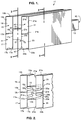
- a compact 5-way waveguide power divider 11 having a first waveguide section 13 with a power input port 15, and second, third, fourth and fifth waveguide sections, identified respectively by reference numerals 17, 19, 21 and 23.
- the first waveguide section 13 has opposite broad walls 25 and opposite narrow walls 27.
- each of the other four parallel waveguide sections have opposite broad walls (a) and narrow walls (b).
- a longitudinal portion (c) of each of the four waveguide sections 17, 19, 21 and 23 are juxtaposed and thus share a common wall with a different longitudinal portion (a, b, c and d) of the broad walls 25 of the first waveguide section 13.
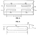
- Directional coupling from the first waveguide section 13 to the four adjacent waveguide sections is provided by individual pairs of relatively narrow elongated coupling members, or slots 31a and 31b, 33a and 33b, 35a and 35b, and 37a and 37b, each pair being disposed in a different one of the longitudinal common wall portions of the waveguides, namely 17c, 19c, 21c and 23c (see Figs. 2 and 4). And, the power thus coupled through the slots, appears as output powers at respective output ports 41, 43, 45 and 47.
- each slot is denoted by the letter L, the width by the letter W, the separation by the letter S, and each slot is offset from the center common walls 17b, 19b and 21b, 23b by a distance denoted by the letter F. It has been found that if the offsets F, the lengths L, and the separations S of the slots are the same for all the waveguides, because of symmetry, the coupled guides 17- 23 will have the same power coupled to each guide from the first waveguide 13.
- the dimensions of the coupling slots, the separation and the offset distance may be calculated in accordance with principles well known in the waveguide art, and/or based on empirical data.
- the coupling slots described herein all have the same parameters (offsets F, lengths L, and separations S) for each the waveguides, resulting in equal power being coupled to all the coupled waveguides, this in general need not be not true.
- the offsets F, lengths L, and separations S may be varied independently in each waveguide to independently control the power coupled to each waveguide, if desired.
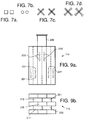
- Figs. 7a-7d illustrate a variety of well-known conventional shapes for the coupling slots of the power divider 11 of Fig. 1.
- Fig. 7a shows square or rectangular cross sectional shapes of the coupling slots 31, 33, 35, 37.
- Fig. 7b shows circular shapes of the coupling slots 31, 33, 35, 37.
- Fig. 7b shows cross shapes of the coupling slots 31, 33, 35, 37.
- Fig. 7b shows dog bone shapes of the coupling slots 31, 33, 35, 37.
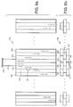
- Figs. 8a and 8b illustrate top and side views of an n-way power divider 11a in accordance with the principles of the present invention.
- the cross sectional pattern shown in the 5-way divider 11 of Fig. 1 are replicated for the n-way divider 11a of Figs. 8a and 8b.
- this embodiment of the invention includes a first waveguide section 113 and a power input port 115. Disposed immediately adjacent the first waveguide section 113 are four waveguide sections 117, 119, 121, and 123. Similar to the previously described embodiment, coupling member pairs 131,133 are located in the common walls, allowing energy to be coupled from the input waveguide sections 113 to the four surrounding waveguide sections.
- additional outer waveguide sections 151 and 153 in conjunction with waveguide sections 119 and 117, are disposed about a central waveguide section 155 which lies immediately adjacent the input waveguide section 113.
- This configuration is mirrored on the opposite side of the input waveguide section 113, using waveguide sections 121, 123, 151', 153' and appropriate coupling members are disposed in common walls of all of these waveguide sections, following the same principles set forth with respect to the first described embodiment.
- a truly compact n-section waveguide power divider is provided in this embodiment.
- FIG. 9a and 9b show top and side views of an n-way power divider 11b illustrating the relative locations of the slots and waveguide sections at the various levels of the power divider 11b.
- this embodiment utilizes coupling member pairs 231, 231', 233, 233' disposed in common walls of adjacent waveguide sections to provide the desired power division.
- the additional n-sections generally extend perpendicular to the width dimension of an input waveguide section 235.
Landscapes
- Waveguides (AREA)
- Variable-Direction Aerials And Aerial Arrays (AREA)
Abstract
An n-way waveguide power divider (11) is disclosed wherein microwave power entering a first waveguide section (13) is directionally coupled simultaneously into a plurality of parallel waveguide sections (17, 19, 21, 23) that share a longitudinal portion (17c, 19c, 21c, 23c) of their broad walls (17a, 19a, 21a, 23a) with a different longitudinal portion of the broad walls (25) of the first waveguide section (13). The power is coupled through an individual pair of elongated axially aligned coupling members (31a, 31b, 33a, 33b, 35a, 35b, 37a, 37b) in each of the shared broad wall longitudinal portions (17c, 19c, 21c, 23c). The coupling members (31a, 31b, 33a, 33b, 35a, 35b, 37a, 37b) may have a variety of shapes including square, rectangular, circular, cross, or dog bone shapes.
Description
- The present invention relates generally to microwave waveguide structures, and more particularly, to waveguide power dividers.
- Directional couplers that incorporate two waveguide structures are well known in the art. For many years, directional couplers have been designed and papers written describing what are known as 2-way power dividers that are constructed using two adjacent waveguides, the power entering one of the waveguides and being coupled through a coupling slot arrangement to the adjacent waveguide from which power is output in a desired direction. For example, such a device is described in a paper by M. Surdin, entitled "Direction Couplers in Wave Guides", Journal IEEE, Vol 93, pt. IIIA, 1946, p. 725. Also, reference may be made to an article by Dennis C. Cooper, entitled "Waveguide Directional Couplers using Inclined Slots", in Microwave Journal, Aug., 1966.
- There are many applications in the microwave art where multiple directional couplers, ganged together, are required to accomplish a task For example, microwave antenna feeding systems and subsystems may require multiple power dividers, and the need to keep the weight and dimensions of these devices as small as possible is very important.
- In the past, the only way to provide such a structure required the coupling together of multiple conventional 2-way power dividers, each consisting of two waveguides. This solution is both bulky and heavy. In applications where the minimization of space required to fabricate such a power divider is an important factor, such a structure could not be used.
- The present invention has the advantage of using the minimum absolute space necessary for a power divider using more than 2 waveguides. This is accomplished using a novel and compact coupling scheme. Thus, it should be recognized that a technique which reduces the weight and space required for a multiple microwave power divider would constitute an important advancement in the art.
- In view of the foregoing factors and conditions characteristic of the prior art, it is a primary objective of the present invention to provide a new and improved compact n-way power divider. Another objective of the present invention is to provide a lighter-weight and less bulky n-way power divider. Still another objective of the present invention is to provide a compact n-way power divider used in building microwave antenna arrays. Yet another objective of the present invention is to provide an n-way power divider that utilizes a novel and compact coupling technique.
- In accordance with an embodiment of the present invention, a compact n-way power divider includes a first waveguide section having a power input port, a pair of opposite broad walls and a pair of opposite narrow walls. Also included is a plurality of parallel waveguide sections, each being parallel to the first waveguide section and each having a pair of opposite broad walls and narrow walls, a longitudinal portion of each of the plurality of waveguide sections being juxtaposed a different longitudinal portion of the first waveguide section, defining common wall portions thereof. The invention also includes coupling means having a pair of coupling members, which may be relatively narrow and elongated slots having a square or rectangular cross section, or may comprise circular or ellipsoidal holes, or may comprise openings in the shape of crosses or dog bones, for example, disposed in each of the common wall portions for directionally coupling power entering the first waveguide section into each of the plurality of waveguide sections.
- According to a presently preferred embodiment of the invention, a 5-way waveguide power divider comprises a first waveguide section and two pairs of parallel waveguide sections, each pair sharing a common narrow wall, and a longitudinal portion of each of the broad walls of these waveguide sections sharing a longitudinal portion of a broad wall of the first waveguide section.
- Thus, the present invention provides for a new approach for a compact antenna feed using a novel coupling scheme. By using this compact directive coupling scheme, an antenna feeding system or subsystem may be built with minimal space requirements.
- Any device which reduces weight and space in antenna feeding systems, such as this invention, is of significant importance to improving the state of the art.
- The various features and advantages of the present invention may be more readily understood with reference to the following detailed description taken in conjunction with the accompanying drawings, wherein like reference numerals designate like structural elements, and in which:
- Fig. 1 is a perspective view of a compact n-way power divider constructed in accordance with the present invention;
- Fig. 2 is a partial section taken along line 2-2 of Fig. 1, in perspective;
- Fig. 3 is a side elevational view of a sectional portion of the n-way power divider of Fig. 1, taken along line 3-3;
- Fig. 4 is an enlarged view of one of the elongated slots shown in Fig. 3;
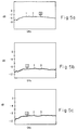
- Fig. 5 is a graphical representation of the output power from each of the ports of the power divider of Fig. 1 with respect to frequency, using the data from Table I;
- Fig. 6 is a graphical representation of the input power of the power divider of Fig. 1 as against the standing wave ratio as seen at the input port, using the data from Table II;
- Figs. 7a-7d illustrate a variety of shapes for the coupling slots of the power divider of Fig. 1; and
- Figs. 8 and 9 illustrate a more complete view of an n-way power divider in accordance with the principles of the present invention.
- Referring now to the drawings, and more particularly to Figs. 1 and 2, there is shown a compact 5-way
waveguide power divider 11 having afirst waveguide section 13 with apower input port 15, and second, third, fourth and fifth waveguide sections, identified respectively byreference numerals - The
first waveguide section 13 has oppositebroad walls 25 and oppositenarrow walls 27. Likewise, each of the other four parallel waveguide sections have opposite broad walls (a) and narrow walls (b). As can be seen in the figures, a longitudinal portion (c) of each of the fourwaveguide sections broad walls 25 of thefirst waveguide section 13. - Directional coupling from the
first waveguide section 13 to the four adjacent waveguide sections is provided by individual pairs of relatively narrow elongated coupling members, orslots respective output ports - The length of each slot is denoted by the letter L, the width by the letter W, the separation by the letter S, and each slot is offset from the center
common walls first waveguide 13. The dimensions of the coupling slots, the separation and the offset distance may be calculated in accordance with principles well known in the waveguide art, and/or based on empirical data. - Although the coupling slots described herein all have the same parameters (offsets F, lengths L, and separations S) for each the waveguides, resulting in equal power being coupled to all the coupled waveguides, this in general need not be not true. The offsets F, lengths L, and separations S may be varied independently in each waveguide to independently control the power coupled to each waveguide, if desired.
- In a 5-way power divider constructed in accordance with the present invention, the power output from the four
output ports input port 15 and the four output ports 41 - 47 for these three frequencies.TABLE I f₁ f₂ f₃ Input port 15 -3.3 -3.3 -3.4 Output port 41 -9.6 -9.4 -9.2 Output port 43 -9.7 -9.5 -9.2 Output port 45 -9.1 -9.0 -8.9 Output port 47 -9.1 -9.0 -9.0 - It has also been found that the 5-way power divider has a relatively low input SWR because of its directive properties. Table II provides the data, and the graph of Fig. 6 shows the relationship of input SWR and frequency for the three above-noted frequencies.
TABLE II f₁ f₂ f₃ Input SWR 1.38 1.05 1.28 - Figs. 7a-7d illustrate a variety of well-known conventional shapes for the coupling slots of the
power divider 11 of Fig. 1. Fig. 7a shows square or rectangular cross sectional shapes of the coupling slots 31, 33, 35, 37. Fig. 7b shows circular shapes of the coupling slots 31, 33, 35, 37. Fig. 7b shows cross shapes of the coupling slots 31, 33, 35, 37. Fig. 7b shows dog bone shapes of the coupling slots 31, 33, 35, 37. - Figs. 8a and 8b illustrate top and side views of an n-
way power divider 11a in accordance with the principles of the present invention. The cross sectional pattern shown in the 5-way divider 11 of Fig. 1 are replicated for the n-way divider 11a of Figs. 8a and 8b. For example, these figures show that this embodiment of the invention includes afirst waveguide section 113 and apower input port 115. Disposed immediately adjacent thefirst waveguide section 113 are fourwaveguide sections input waveguide sections 113 to the four surrounding waveguide sections. - Extending this technique, additional
outer waveguide sections waveguide sections input waveguide section 113. This configuration is mirrored on the opposite side of theinput waveguide section 113, usingwaveguide sections - Finally, Fig. 9a and 9b show top and side views of an n-
way power divider 11b illustrating the relative locations of the slots and waveguide sections at the various levels of thepower divider 11b. Like thepower divider 11a, this embodiment utilizes coupling member pairs 231, 231', 233, 233' disposed in common walls of adjacent waveguide sections to provide the desired power division. However, unlike the extension of theadditional waveguide sections embodiment 11a), in this embodiment, the additional n-sections generally extend perpendicular to the width dimension of aninput waveguide section 235. - Thus there has been described a new and improved N-way waveguide power divider. It is to be understood that the above-described embodiment is merely illustrative of some of the many specific embodiments which represent applications of the principles of the present invention. Clearly, numerous and other arrangements can be readily devised by those skilled in the art without departing from the scope of the invention.
Claims (14)
- A compact n-way waveguide power divider (11; 111a;11b), comprising:- a first waveguide section (13; 113; 235) having a power input port (15; 115), a pair of opposite broad walls (25) and a pair of opposite narrow walls (27),characterized by:- a plurality of parallel waveguide sections (17, 19, 21, 23; 117, 119, 121, 123; 217, 219, 221, 223), each being parallel to first waveguide section (13; 113; 235) and each having a pair of opposite broad walls (17a, 19a, 21a, 23a) and narrow walls (17b, 19b, 21b, 23b), a longitudinal portion of each of said plurality of waveguide sections (17, 19, 21, 23; 117, 119, 121, 123; 217, 219, 221, 223) being juxtaposed a different longitudinal portion of said first waveguide section (13; 113; 235) defining common wall portions (17c, 19c, 21c, 23c) thereof; and- coupling means including a pair of relatively narrow coupling members (31a, 31b, 33a, 33b, 35a, 35b, 37a, 37b; 131, 133; 231, 233) disposed in each of said common wall portions (17c, 19c, 21c, 23c) for directionally coupling power entering said first waveguide section (13; 113; 235) into each of said plurality of waveguide sections (17, 19, 21, 23; 117, 119, 121, 123; 217, 219, 221, 223).
- The power divider of claim 1, characterized in that said pair of coupling members (31a, 31b, 33a, 33b, 35a, 35b, 37a, 37b; 131, 133; 231, 233) comprise relatively narrow alongated coupling slots.
- The power divider of claim 2, characterized in that said pair of coupling slots have a common axis and are separated by a predetermined separation (S).
- The power divider of claim 2 or 3, characterized in that said coupling slots have predetermined width (W) and offset (F) dimensions.
- The power divider of any of claims 1 - 4, characterized in that said plurality of waveguide sections (17, 19, 21, 23) comprises four waveguide sections (17, 19, 21, 23).
- The power divider of claim 5, characterized in that said four waveguide sections (17, 19, 21, 23) comprise two pairs (17/19, 21/23) of waveguide sections, each pair (17/19, 21/23) sharing a common narrow wall (17b, 21b).
- The power divider of claim 6, characterized in that each of said pairs (17/19, 21/23) of waveguide sections share a common wall (17a, 19a, 21a, 23a) with a different broad wall (25) of set first waveguide section (13).
- The power divider of any of claims 4 - 7, characterized in that said offsets (F), lengths (L) and separations (S) of said slots are the same for each of said common wall portions (17c, 19c, 21c, 23c).
- The power divider of any of claims 4 - 7, characterized in that selected ones of said offsets (F), lengths (L) and separations (S) of said slots are varied for selected ones of said common wall portions (17c, 19c, 21c, 23c), to vary the amount of power coupled to individual ones of the waveguide sections (17, 19, 21, 23).
- The power divider of any of claims 1 - 9, characterized in that said pair of coupling members comprise openings having circular shapes.
- The power divider of any of claims 1 - 9, characterized in that said pair of coupling members comprise openings having cross shapes.
- The power divider of any of claims 1 - 9, characterized in that said pair of coupling members comprise openings having dog bone shapes.
- The power divider of any of claims 1 - 9, characterized in that said pair of coupling members comprise openings having rectangular shapes.
- The power divider of any of claims 1 - 13, characterized by an even number of additional first waveguide sections (151, 151', 153, 153'), and wherein said plurality of waveguide sections (117, 119, 121, 123; 217, 219, 221, 223) comprise even numbers of additional ones of such sections (151, 151', 153, 153') in excess of four waveguide sections.
Applications Claiming Priority (2)
| Application Number | Priority Date | Filing Date | Title |
|---|---|---|---|
| US722727 | 1991-06-27 | ||
| US07/722,727 US5196812A (en) | 1991-06-27 | 1991-06-27 | Compact n-way waveguide power divider |
Publications (2)
| Publication Number | Publication Date |
|---|---|
| EP0520501A2 true EP0520501A2 (en) | 1992-12-30 |
| EP0520501A3 EP0520501A3 (en) | 1994-06-15 |
Family
ID=24903131
Family Applications (1)
| Application Number | Title | Priority Date | Filing Date |
|---|---|---|---|
| EP19920110851 Withdrawn EP0520501A3 (en) | 1991-06-27 | 1992-06-26 | Compact n-way waveguide power divider |
Country Status (6)
| Country | Link |
|---|---|
| US (1) | US5196812A (en) |
| EP (1) | EP0520501A3 (en) |
| JP (1) | JPH05191114A (en) |
| KR (1) | KR930001508A (en) |
| AU (1) | AU642824B2 (en) |
| CA (1) | CA2072392A1 (en) |
Cited By (1)
| Publication number | Priority date | Publication date | Assignee | Title |
|---|---|---|---|---|
| FR2701797A1 (en) * | 1993-02-18 | 1994-08-26 | Commissariat Energie Atomique | Microwave power transfer coupler to plasma ply and linear microwave source for plasma surface treatment. |
Families Citing this family (7)
| Publication number | Priority date | Publication date | Assignee | Title |
|---|---|---|---|---|
| US5416452A (en) * | 1993-03-09 | 1995-05-16 | Bell Communications Research, Inc. | Mode diversity coupler for vertical polarization |
| ES2231557T3 (en) | 2000-08-31 | 2005-05-16 | Raytheon Company | MECHANICALLY ORIENTABLE ELEMENT SYSTEM ANTENNA. |
| US6653985B2 (en) | 2000-09-15 | 2003-11-25 | Raytheon Company | Microelectromechanical phased array antenna |
| US6897739B2 (en) * | 2003-03-13 | 2005-05-24 | Northrop Grumman Corporation | Waveguide power divider and combiner utilizing a resistive slot |
| US8928429B2 (en) | 2011-05-17 | 2015-01-06 | City University Of Hong Kong | Multiple-way ring cavity power combiner and divider |
| US10181630B2 (en) * | 2016-08-08 | 2019-01-15 | Rohde & Schwarz Gmbh & Co. Kg | Directional coupler and a combiner |
| KR102472839B1 (en) * | 2020-10-14 | 2022-12-01 | 주식회사 티알신소재 | coating method for metal pipe interior |
Citations (3)
| Publication number | Priority date | Publication date | Assignee | Title |
|---|---|---|---|---|
| GB1370229A (en) * | 1971-08-31 | 1974-10-16 | Int Standard Electric Corp | Variable directional coupler |
| US4520329A (en) * | 1982-02-25 | 1985-05-28 | Italtel Societa Italiana Telecomunicazioni S.P.A. | Circuit component for separating and/or combining two isofrequential but differently polarized pairs of signal waves lying in different high-frequency bands |
| US4792770A (en) * | 1987-06-29 | 1988-12-20 | General Electric Company | Waveguide directional coupler with multiple coupled outputs |
Family Cites Families (9)
| Publication number | Priority date | Publication date | Assignee | Title |
|---|---|---|---|---|
| DE133384C (en) * | ||||
| US2585173A (en) * | 1948-07-01 | 1952-02-12 | Raytheon Mfg Co | Radio-frequency transmission line circuit |
| US2779001A (en) * | 1952-05-28 | 1957-01-22 | Gen Electric | Directional coupler |
| US3045238A (en) * | 1960-06-02 | 1962-07-17 | Theodore C Cheston | Five aperture direction finding antenna |
| US3230483A (en) * | 1963-12-30 | 1966-01-18 | Gen Electric | Anchor-slot waveguide coupling aperture |
| JPS5811306B2 (en) * | 1979-06-29 | 1983-03-02 | 三井造船株式会社 | Underwater cutting device for radioactively contaminated metal |
| JPH0650801B2 (en) * | 1986-12-23 | 1994-06-29 | 三菱電機株式会社 | Waveguide demultiplexer |
| US5010351A (en) * | 1990-02-08 | 1991-04-23 | Hughes Aircraft Company | Slot radiator assembly with vane tuning |
| US4985708A (en) * | 1990-02-08 | 1991-01-15 | Hughes Aircraft Company | Array antenna with slot radiators offset by inclination to eliminate grating lobes |
-
1991
- 1991-06-27 US US07/722,727 patent/US5196812A/en not_active Expired - Lifetime
-
1992
- 1992-06-25 CA CA002072392A patent/CA2072392A1/en not_active Abandoned
- 1992-06-26 AU AU18680/92A patent/AU642824B2/en not_active Ceased
- 1992-06-26 EP EP19920110851 patent/EP0520501A3/en not_active Withdrawn
- 1992-06-27 KR KR1019920011373A patent/KR930001508A/en not_active Application Discontinuation
- 1992-06-29 JP JP4171313A patent/JPH05191114A/en active Pending
Patent Citations (3)
| Publication number | Priority date | Publication date | Assignee | Title |
|---|---|---|---|---|
| GB1370229A (en) * | 1971-08-31 | 1974-10-16 | Int Standard Electric Corp | Variable directional coupler |
| US4520329A (en) * | 1982-02-25 | 1985-05-28 | Italtel Societa Italiana Telecomunicazioni S.P.A. | Circuit component for separating and/or combining two isofrequential but differently polarized pairs of signal waves lying in different high-frequency bands |
| US4792770A (en) * | 1987-06-29 | 1988-12-20 | General Electric Company | Waveguide directional coupler with multiple coupled outputs |
Cited By (1)
| Publication number | Priority date | Publication date | Assignee | Title |
|---|---|---|---|---|
| FR2701797A1 (en) * | 1993-02-18 | 1994-08-26 | Commissariat Energie Atomique | Microwave power transfer coupler to plasma ply and linear microwave source for plasma surface treatment. |
Also Published As
| Publication number | Publication date |
|---|---|
| EP0520501A3 (en) | 1994-06-15 |
| AU642824B2 (en) | 1993-10-28 |
| CA2072392A1 (en) | 1992-12-28 |
| AU1868092A (en) | 1993-01-07 |
| KR930001508A (en) | 1993-01-16 |
| US5196812A (en) | 1993-03-23 |
| JPH05191114A (en) | 1993-07-30 |
Similar Documents
| Publication | Publication Date | Title |
|---|---|---|
| DE60217694T2 (en) | ADJUSTABLE ANTENNA TRUCK WITH INTEGRATED PHASE SLIDER | |
| US5638079A (en) | Slotted waveguide array antennas | |
| EP0315064B1 (en) | Waveguide matrix including in-plane crossover | |
| US5019831A (en) | Dual end resonant slot array antenna feed having a septum | |
| Abouzahra et al. | Multiport power divider-combiner circuits using circular-sector-shaped planar components | |
| US5650793A (en) | Centered longitudinal series/series coupling slot for coupling energy between a boxed stripline and a crossed rectangular waveguide and antenna array employing same | |
| EP0520501A2 (en) | Compact N-way waveguide power divider | |
| DE69927637T2 (en) | Boxhorn group arrangement with folded branches | |
| EP0267229B1 (en) | Switchable multi-power-level short slot waveguide hybrid coupler | |
| EP0313058B1 (en) | Coaxial transmission-line matrix including in-plane crossover | |
| US4409595A (en) | Stripline slot array | |
| CN110444904B (en) | Air-filled metal planar array antenna | |
| EP0209220A1 (en) | Dual end resonant slot array antenna feed | |
| US3988702A (en) | Waveguide section for connecting rectangular waveguide with elliptical waveguide | |
| DE3516190C2 (en) | Electrically phase controlled antenna arrangement | |
| US6956447B2 (en) | Directional coupler using non-radiative dielectric waveguide | |
| US4797643A (en) | Coaxial hybrid coupler and crossing element | |
| US5212462A (en) | Stripline microwave module having means for contactless coupling between signal lines on different planar levels | |
| US4556855A (en) | RF Components and networks in shaped dielectrics | |
| JPH03117003A (en) | Waveguide network | |
| CA2003471C (en) | Feed waveguide for an array antenna | |
| SE463489B (en) | FAILURING TRANSITIONAL TRANSITION | |
| Smith | Multiple beam crossovers for a lens-fed antenna array | |
| US6429757B1 (en) | Coupling arrangement for a stripline network | |
| EP0975046B1 (en) | Array antenna |
Legal Events
| Date | Code | Title | Description |
|---|---|---|---|
| PUAI | Public reference made under article 153(3) epc to a published international application that has entered the european phase |
Free format text: ORIGINAL CODE: 0009012 |
|
| AK | Designated contracting states |
Kind code of ref document: A2 Designated state(s): CH DE ES FR GB IT LI SE |
|
| PUAL | Search report despatched |
Free format text: ORIGINAL CODE: 0009013 |
|
| AK | Designated contracting states |
Kind code of ref document: A3 Designated state(s): CH DE ES FR GB IT LI SE |
|
| 17P | Request for examination filed |
Effective date: 19941206 |
|
| STAA | Information on the status of an ep patent application or granted ep patent |
Free format text: STATUS: THE APPLICATION IS DEEMED TO BE WITHDRAWN |
|
| 18D | Application deemed to be withdrawn |
Effective date: 19970103 |