EP0519775A1 - In Betriebszeit rekonfigurierbarer Antennenreflektor - Google Patents
In Betriebszeit rekonfigurierbarer Antennenreflektor Download PDFInfo
- Publication number
- EP0519775A1 EP0519775A1 EP92401441A EP92401441A EP0519775A1 EP 0519775 A1 EP0519775 A1 EP 0519775A1 EP 92401441 A EP92401441 A EP 92401441A EP 92401441 A EP92401441 A EP 92401441A EP 0519775 A1 EP0519775 A1 EP 0519775A1
- Authority
- EP
- European Patent Office
- Prior art keywords
- reflector according
- reflecting surface
- actuators
- layer
- fibers
- Prior art date
- Legal status (The legal status is an assumption and is not a legal conclusion. Google has not performed a legal analysis and makes no representation as to the accuracy of the status listed.)
- Withdrawn
Links
Images


Classifications
-
- H—ELECTRICITY
- H01—ELECTRIC ELEMENTS
- H01Q—ANTENNAS, i.e. RADIO AERIALS
- H01Q15/00—Devices for reflection, refraction, diffraction or polarisation of waves radiated from an antenna, e.g. quasi-optical devices
- H01Q15/14—Reflecting surfaces; Equivalent structures
- H01Q15/147—Reflecting surfaces; Equivalent structures provided with means for controlling or monitoring the shape of the reflecting surface
Definitions
- the invention relates to a variable geometry antenna reflector intended to cover (by transmission and / or reception), from a spacecraft such as a satellite, a ground area having a non-circular contour, for example surrounding a country or group of countries (see Figure 1) that you want to be able to modify during the operational life of the spacecraft.
- a spacecraft such as a satellite
- a ground area having a non-circular contour, for example surrounding a country or group of countries (see Figure 1) that you want to be able to modify during the operational life of the spacecraft.
- the invention is primarily aimed at a spatial application, it is understood that it can more generally be applied to any antenna reflector which, in service, it is desired to be able to modify the shape of the beam without changing the reflector (for example in the field of large, albeit very precise, telescopes).
- the conventional method of obtaining a beam with a contour formed consists in using a multiple source illuminating, according to an adapted law of illumination, a system of eccentric reflector (s) simple or double.
- the beam is obtained by exciting the elements of the source with optimized phases and amplitudes, using a signal formation network comprising waveguides (in English "beam forming network").
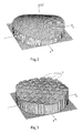
- Another method for obtaining a radiation diagram having the desired contour consists in using a single source associated with a system of reflector (s) with formed surface (that is to say having a specific geometry, for example non-quadratic such that that of Figure 2).
- the variations in optical path between the source and different points of the reflector make it possible to generate a phase and amplitude diagram corresponding to the characteristics of the desired radiation diagram.
- reconfigurable antenna systems are conventionally obtained by integrating power dividers and phase shifters with variable characteristics into the training network. This makes the multiple source very complex and therefore causes losses of radioelectric energy, risks of passive intermodulation products in the case of a transmitting antenna, restrictive thermal regulation for the platform of the satellite and a penalizing mass.
- An alternative solution for reconfiguring a reflector antenna in orbit consists in using a system of one or more reflectors whose reflective surfaces are made deformable so as to be able to modify the radiation diagram.
- this deformable surface behaves like a membrane so that the reflecting surface has many singularities (see for example Figure 3). Consequently, setting the reflector to precise profile despite these singularities requires a high number of control points.
- the object of the invention is to overcome the aforementioned drawbacks by minimizing the presence of artefacts, such as the aforementioned features, on the surface of an antenna reflector which can be reconfigured in service.
- the solution proposed to obtain a regular surface consists in using a reflective and elastically deformable skin having a stiffness in bending, while being sufficiently flexible at the place of its interfaces with the bearing structure or the actuators so as to limit the efforts and the deformation energies.
- the invention provides an antenna reflector that can be reconfigured in service, comprising a rigid support structure, a deformable reflecting surface having radio-electric reflectivity properties, and actuators acting on this deformable reflecting surface to deform it, characterized in that this reflecting surface is elastically deformable with a stiffness in bending, and in that the actuators act, at control points on this deformable reflecting surface, transverse thereto.
- FIG. 1 is an example of coverage, by a beam antenna, of a geographical area of the terrestrial globe (denoted T), centered on Europe and extending in the north to Scandinavia, in the east to '' at the borders of the USSR, in the South to North Africa and in the West up to the Atlantic Ocean including the Azores islands.
- Various radiation isopower curves are reported, ranging between 21.5 dBi and 30.5 dBi.
- FIG. 2 Such radiation patterns are conventionally obtained using reflectors having a left surface, FIG. 2 of which gives the deviation parallel to Z to a reference paraboloid, in a simple example, in a frame (X, Y, Z) where Z is at least approximately oriented in the direction of transmission (or reception).
- This reflecting surface 4 of thickness typically between 25 ⁇ m and 1 mm, is stretched over the light load-bearing structure 5 which typically consists of a grid with triangular or rectangular meshes of wires having a bending stiffness (metallic wires or glass fibers , Kevlar, carbon coated with a thermosetting or thermoplastic matrix), and of mesh size typically between 30 and 300 mm (more generally between 10 and 1000 mm).
- This reflecting surface can itself be a knitted fabric with a mesh size typically between 0.2 and 6 mm.
- Figures 5 to 7 show an embodiment of a reflector according to the block diagram of Figure 4. Elements similar to those of Figure 4 are assigned the same reference numerals.
- the rigid structure 2 is represented in FIG. 5 as schematically as in FIG. 4, with a bottom 9 allowing the implantation and the support of the actuators and a cylindrical side wall 10 on the edge or edge 13 of which is fixed , at a distance from this bottom, the periphery of the skin 1, identified 6 in FIG. 4.
- the light supporting structure 5 is formed of two plies of crossed wires or bands 11 and 12 connected near their ends to said free edge 13 of the cylindrical wall 10 materializing the periphery 6 of the skin 1 (see FIG. 5).
- This connection is made by any suitable means, for example by holes provided in this cylindrical wall 10 and directly receiving the ends of the light supporting structure (that is to say in practice the curved ends of the wires which constitute this structure) .
- the flexible reflecting surface 4 which covers the light supporting surface 5 is itself fixed at its periphery on the edge 13 of the cylindrical wall so as to be kept in tension.
- This fixing is carried out by any suitable means, for example by sewing, gluing or by "VELCRO" type fasteners. Only a part is shown in Figures 5 and 7. It is attached to the son or bands 11, 12 and 13 by any suitable known means, for example by gluing or sewing with KEVLAR wire. Examples of these sewing points along the threads are identified at 16 in FIGS. 5 and 7. As we have seen above, the representation of this skin by a lattice is only offered by way of example.
- control points P are in practice chosen in at least some of the crossings of wires 11 and 12. In FIG. 6, these control points are provided every two wires, with wires intermediate between the wires connecting these control points. These intermediate wires have been omitted in FIG. 5 for the sake of readability. We can of course, as a variant, consider each wire crossing as a control point.
- a particular control point is chosen at the center of the skin 1, here marked P o , which constitutes a reference point for the whole of the skin.
- This point P o is in practice located at the intersection of the central wires whose connections with the border 13 are surrounded by circles 14.
- the reflective surface is profiled by synchronized or sequential control of the motorized actuators which act on control points.
- These actuators can push and pull the reflecting surface, in a direction close to its perpendicular.
- FIG. 8 shows, in half-section, a preferred embodiment of an actuator 3, having degrees of freedom in rotation both at its junction at the bottom 9 of the support structure 2 and at its junction at a point of control P.
- This actuator comprises a driving part 20 linked to the bottom 9, and a driven part 21 linked to the point P.
- This driving part 20 comprises a motor 22 controlled in any suitable known manner, through a control circuit marked 8 in FIG. 4, and a screw 23 adapted to be controlled in rotation but fixed axially.
- the driven part 21 comprises a tubular portion 24 forming a nut, free axially with respect to the driving part but coupled in rotation.
- the driving part is coupled by a cardan link marked 25 to a fixing flange 26 screwed to the bottom 9. Two degrees of freedom in rotation are thus produced around axes transverse to the actuator.
- the driven part 21 carries a pivoting stirrup 27, articulated around a first transverse axis X1.
- this pivoting stirrup is pivotally mounted, around a second axis X2 perpendicular to the first axis, a connecting piece 28 subject to point P.
- the pivoting bracket alone makes it possible to provide sufficient clearance for the point P.
- the universal joint 25 located at the base of the actuator can then advantageously be replaced by a rigid connection without degree of freedom .
- the connections shown diagrammatically by the circles 14 can be materialized by circular holes while the connections with two degrees of freedom of translation, shown diagrammatically by the ellipses 15 can be materialized by oblong holes located in the rigid support structure near the contour of the reflecting surface.
- FIG. 11 shows an example of surface geometry thus obtained. We can observe depressions at the control points P, but that these are much less marked than in the prior art of which FIG. 3 is a representative example.
- the invention does not concern the theoretical determination of the geometry to be given to one (or more) reflector (s) to obtain a beam having the desired contour, but the structure to be given to this reflector in order to materialize this set geometry.
Landscapes
- Physics & Mathematics (AREA)
- Electromagnetism (AREA)
- Aerials With Secondary Devices (AREA)
Applications Claiming Priority (2)
| Application Number | Priority Date | Filing Date | Title |
|---|---|---|---|
| FR9107534A FR2678111B1 (fr) | 1991-06-19 | 1991-06-19 | Reflecteur d'antenne reconfigurable en service. |
| FR9107534 | 1991-06-19 |
Publications (1)
| Publication Number | Publication Date |
|---|---|
| EP0519775A1 true EP0519775A1 (de) | 1992-12-23 |
Family
ID=9414042
Family Applications (1)
| Application Number | Title | Priority Date | Filing Date |
|---|---|---|---|
| EP92401441A Withdrawn EP0519775A1 (de) | 1991-06-19 | 1992-05-26 | In Betriebszeit rekonfigurierbarer Antennenreflektor |
Country Status (5)
| Country | Link |
|---|---|
| US (1) | US5440320A (de) |
| EP (1) | EP0519775A1 (de) |
| JP (1) | JPH05191134A (de) |
| CA (1) | CA2070793A1 (de) |
| FR (1) | FR2678111B1 (de) |
Cited By (1)
| Publication number | Priority date | Publication date | Assignee | Title |
|---|---|---|---|---|
| EP2648281A1 (de) * | 2012-04-06 | 2013-10-09 | Thales | Rekonfigurierbarer Antennenreflektor |
Families Citing this family (42)
| Publication number | Priority date | Publication date | Assignee | Title |
|---|---|---|---|---|
| US5680145A (en) * | 1994-03-16 | 1997-10-21 | Astro Aerospace Corporation | Light-weight reflector for concentrating radiation |
| IT1284301B1 (it) * | 1996-03-13 | 1998-05-18 | Space Engineering Spa | Antenna a singolo o a doppio riflettore, a fasci sagomati, a polarizzazione lineare. |
| US5945960A (en) * | 1996-12-02 | 1999-08-31 | Space Systems/Loral, Inc. | Method and apparatus for reconfiguring antenna radiation patterns |
| US6195067B1 (en) * | 1999-02-09 | 2001-02-27 | Trw Inc. | Remotely adjustable mesh deployable reflectors |
| US6313811B1 (en) | 1999-06-11 | 2001-11-06 | Harris Corporation | Lightweight, compactly deployable support structure |
| US6618025B2 (en) | 1999-06-11 | 2003-09-09 | Harris Corporation | Lightweight, compactly deployable support structure with telescoping members |
| US6724130B1 (en) | 1999-10-22 | 2004-04-20 | The United States Of America As Represented By The Administrator Of The National Aeronautics And Space Administration | Membrane position control |
| AU1340501A (en) * | 1999-10-22 | 2001-05-08 | Government of the United States of America as represented by the Administrator of the National Aeronautics and Space Administration (NASA), The | Membrane position control |
| US7015624B1 (en) | 1999-10-22 | 2006-03-21 | The United States Of America As Represented By The Administrator Of The National Aeronautics And Space Administration | Non-uniform thickness electroactive device |
| US6424090B1 (en) * | 1999-11-12 | 2002-07-23 | Gti | Modification of millimetric wavelength microwave beam power distribution |
| US6268835B1 (en) * | 2000-01-07 | 2001-07-31 | Trw Inc. | Deployable phased array of reflectors and method of operation |
| US6208317B1 (en) * | 2000-02-15 | 2001-03-27 | Hughes Electronics Corporation | Hub mounted bending beam for shape adjustment of springback reflectors |
| US7013183B1 (en) * | 2000-07-14 | 2006-03-14 | Solvisions Technologies Int'l | Multiplexer hardware and software for control of a deformable mirror |
| ITBO20020012A1 (it) * | 2002-01-11 | 2003-07-11 | Consiglio Nazionale Ricerche | Apparecchiatura per il rilevamento di radiazioni elettromagnetiche , in particolare per applicazioni radioastronomiche |
| US6951397B1 (en) * | 2002-03-19 | 2005-10-04 | Lockheed Martin Corporation | Composite ultra-light weight active mirror for space applications |
| US7460067B2 (en) * | 2004-12-06 | 2008-12-02 | Lockheed-Martin Corporation | Systems and methods for dynamically compensating signal propagation for flexible radar antennas |
| US7173575B2 (en) * | 2005-01-26 | 2007-02-06 | Andrew Corporation | Reflector antenna support structure |
| JP2007173320A (ja) * | 2005-12-19 | 2007-07-05 | Denso Corp | 積層型圧電素子及びその製造方法 |
| US7570226B2 (en) * | 2006-02-28 | 2009-08-04 | The Boeing Company | Method and apparatus for grating lobe control in faceted mesh reflectors |
| US7595769B2 (en) * | 2006-02-28 | 2009-09-29 | The Boeing Company | Arbitrarily shaped deployable mesh reflectors |
| DE602007004991D1 (de) | 2007-09-21 | 2010-04-08 | Europ Agence Spatiale | Wiederkonfigurierbarer Reflektor für Radiofrequenzwellen |
| US8860627B2 (en) * | 2007-09-24 | 2014-10-14 | Agence Spatiale Europeenne | Reconfigurable reflector for electromagnetic waves |
| WO2011072845A2 (en) | 2009-12-16 | 2011-06-23 | Adant Srl | Metamaterial reconfigurable antennas |
| FR2956927B1 (fr) | 2010-02-26 | 2012-04-20 | Thales Sa | Membrane reflechissante deformable pour reflecteur reconfigurable, reflecteur d'antenne reconfigurable et antenne comportant une telle membrane |
| FR2973168B1 (fr) * | 2011-03-24 | 2013-05-17 | Thales Sa | Systeme d'actionnement pour reflecteur d'antenne a surface reflechissante deformable |
| US9252482B2 (en) | 2012-10-24 | 2016-02-02 | Intel Corporation | Magnetic field pass through surfaces in carbon fiber reinforced polymers |
| US10020576B2 (en) | 2013-03-15 | 2018-07-10 | Orbital Sciences Corporation | Systems and methods for reconfigurable faceted reflector antennas |
| US9203156B2 (en) * | 2013-03-15 | 2015-12-01 | Orbital Sciences Corporation | Systems and methods for reconfigurable faceted reflector antennas |
| FR3006504B1 (fr) | 2013-05-31 | 2016-09-02 | Thales Sa | Procede de realisation d'un reflecteur d'antenne a surface formee, reflecteur a surface formee obtenu par ce procede et antenne comportant un tel reflecteur |
| RU2571718C2 (ru) * | 2013-10-02 | 2015-12-20 | Акционерное общество "Информационные спутниковые системы" имени академика М.Ф. Решетнёва" | Прецизионный рефлектор и способ его изготовления |
| US9577344B2 (en) * | 2013-11-27 | 2017-02-21 | The United States of Americ as represented by the Secretary of the Air Force | Actuated pin antenna reflector |
| RU2576493C2 (ru) * | 2014-06-17 | 2016-03-10 | Государственное казенное образовательное учреждение высшего профессионального образования Академия Федеральной службы охраны Российской Федерации (Академия ФСО России) | Способ синтеза формы отражающей поверхности антенной системы зеркального типа |
| JP6390949B2 (ja) * | 2014-06-25 | 2018-09-19 | Necスペーステクノロジー株式会社 | 展開式メッシュアンテナ |
| CN107210536B (zh) | 2014-12-05 | 2021-07-30 | Nsl通讯有限公司 | 远程可调谐的天线组件及其副反射器和相关方法 |
| RU172553U1 (ru) * | 2016-12-27 | 2017-07-12 | федеральное государственное бюджетное образовательное учреждение высшего образования "Московский государственный технический университет имени Н.Э. Баумана (национальный исследовательский университет)" (МГТУ им. Н.Э. Баумана) | Технологическая оснастка для формирования размеростабильного антенного рефлектора из полимерных композиционных материалов на основе углеродных армирующих систем |
| JP6559737B2 (ja) * | 2017-06-21 | 2019-08-14 | ソフトバンク株式会社 | 無給電中継装置及び無線中継システム |
| US11522297B2 (en) | 2018-05-30 | 2022-12-06 | M.M.A. Design, LLC | Deployable cylindrical parabolic antenna |
| US10727605B2 (en) | 2018-09-05 | 2020-07-28 | Eagle Technology, Llc | High operational frequency fixed mesh antenna reflector |
| US10461421B1 (en) * | 2019-05-07 | 2019-10-29 | Bao Tran | Cellular system |
| US11728572B1 (en) * | 2019-12-11 | 2023-08-15 | Raytheon Company | Twistarray reflector for axisymmetric incident fields |
| US11722211B1 (en) | 2020-02-13 | 2023-08-08 | Ast & Science, Llc | AOCS system to maintain planarity for space digital beam forming using carrier phase differential GPS, IMU and magnet torques on large space structures |
| US11973274B2 (en) * | 2020-05-18 | 2024-04-30 | Arizona Board Of Regents On Behalf Of Arizona State University | Single-switch-per-bit topology for reconfigurable reflective surfaces |
Citations (2)
| Publication number | Priority date | Publication date | Assignee | Title |
|---|---|---|---|---|
| EP0290124A2 (de) * | 1987-05-07 | 1988-11-09 | Trw Inc. | Hybrides Netz und Mikrowellenreflector mit einem solchen Netz |
| WO1989001708A1 (en) * | 1987-08-10 | 1989-02-23 | Hughes Aircraft Company | Method and structure for reflectror surface adjustment |
Family Cites Families (6)
| Publication number | Priority date | Publication date | Assignee | Title |
|---|---|---|---|---|
| US2945234A (en) * | 1958-05-05 | 1960-07-12 | Avco Mfg Corp | Collapsible reflecting structure for electric waves |
| DE2460807C3 (de) * | 1974-12-21 | 1981-04-02 | Messerschmitt-Bölkow-Blohm GmbH, 8000 München | Flächenhaftes Leichtbauteil aus faserverstärktem Kunststoff |
| US4750002A (en) * | 1986-09-12 | 1988-06-07 | Harris Corporation | Antenna panel having adjustable supports to improve surface accuracy |
| FR2617453B1 (fr) * | 1987-07-01 | 1989-10-20 | Caoutchouc Manuf Plastique | Dispositif destine a assurer la continuite de passage entre deux vehicules successifs ferroviaires ou routiers |
| US4989015A (en) * | 1987-10-26 | 1991-01-29 | Hughes Aircraft Company | Unfurlable mesh reflector |
| US5162811A (en) * | 1991-01-31 | 1992-11-10 | Lammers Uve H W | Paraboloidal reflector alignment system using laser fringe pattern |
-
1991
- 1991-06-19 FR FR9107534A patent/FR2678111B1/fr not_active Expired - Fee Related
-
1992
- 1992-05-26 EP EP92401441A patent/EP0519775A1/de not_active Withdrawn
- 1992-06-09 CA CA002070793A patent/CA2070793A1/en not_active Abandoned
- 1992-06-19 JP JP4160527A patent/JPH05191134A/ja active Pending
-
1994
- 1994-08-18 US US08/292,607 patent/US5440320A/en not_active Expired - Fee Related
Patent Citations (2)
| Publication number | Priority date | Publication date | Assignee | Title |
|---|---|---|---|---|
| EP0290124A2 (de) * | 1987-05-07 | 1988-11-09 | Trw Inc. | Hybrides Netz und Mikrowellenreflector mit einem solchen Netz |
| WO1989001708A1 (en) * | 1987-08-10 | 1989-02-23 | Hughes Aircraft Company | Method and structure for reflectror surface adjustment |
Non-Patent Citations (3)
| Title |
|---|
| 18TH EUROPEAN MICROWAVE CONFERENCE 88 Septembre 1988, STOCKHOLM,SWEDEN pages 482 - 487; CLARRICOATS ET AL.: 'A RECONFIGURABLE SATELLITE REFLECTOR ANTENNA' * |
| ELECTRONICS LETTERS. vol. 27, no. 1, 3 Janvier 1991, STEVENAGE,GB pages 64 - 65; HAI ET AL.: 'EXPERIMENTAL VERIFICATION OF AN ELECTRONICALLY CONTROLLED RECONFIGURABLE REFLECTOR ANTENNA' * |
| MICROWAVE ENGINEERING EUROPE Juin 1991, page 15; 'Mesh antennas pulled into shape' * |
Cited By (3)
| Publication number | Priority date | Publication date | Assignee | Title |
|---|---|---|---|---|
| EP2648281A1 (de) * | 2012-04-06 | 2013-10-09 | Thales | Rekonfigurierbarer Antennenreflektor |
| FR2989229A1 (fr) * | 2012-04-06 | 2013-10-11 | Thales Sa | Reflecteur d'antenne reconfigurable en service |
| US9368876B2 (en) | 2012-04-06 | 2016-06-14 | Thales | In-service reconfigurable antenna reflector |
Also Published As
| Publication number | Publication date |
|---|---|
| FR2678111B1 (fr) | 1993-10-22 |
| FR2678111A1 (fr) | 1992-12-24 |
| CA2070793A1 (en) | 1992-12-20 |
| US5440320A (en) | 1995-08-08 |
| JPH05191134A (ja) | 1993-07-30 |
Similar Documents
| Publication | Publication Date | Title |
|---|---|---|
| EP0519775A1 (de) | In Betriebszeit rekonfigurierbarer Antennenreflektor | |
| EP0497249B1 (de) | Gruppenantenne, insbesondere zur Verwendung im Weltraum | |
| EP1676776B1 (de) | Verbindungsvorrichtung für Elemente einer Raumfahrtausrüstung mit flexiblen ausbringbaren Blättern | |
| EP2503641B1 (de) | Betätigungssystem für Antennenreflektor mit einer deformierbaren reflektierenden Fläche | |
| FR2526552A1 (de) | ||
| EP2808943B1 (de) | Herstellungsverfahren eines Antennenreflektors mit geformter Oberfläche, mit diesem Verfahren hergestellter geformter Reflektor und Antenne, die einen solchen Reflektor umfasst | |
| FR2533374A1 (fr) | Dispositif de montage d'antenne | |
| EP2144105B1 (de) | Vorrichtung zum Korrigieren der optischen Fehler eines Teleskopspiegels | |
| EP0546913B1 (de) | Antenne mit feststehendem Reflektor für mehrere Strahlen von Kommunikationssystemen | |
| EP2362489B1 (de) | Reflektierende verformbare Membran für rekonfigurierbaren Reflektor, rekonfigurierbarer Antennenreflektor und mit einer solchen Membran ausgestattete Antenne | |
| FR2531817A1 (fr) | Structure d'antenne | |
| FR2558991A1 (fr) | Antenne a reflecteur pour le fonctionnement dans plusieurs gammes de frequence | |
| FR2814216A1 (fr) | Dispositif d'orientation et systeme d'orientation embarque | |
| FR2598339A1 (fr) | Antennes a reflecteurs paraboliques et leur procede d'obtention | |
| US20120176693A1 (en) | Layered Mirror Assembly | |
| JP2013219768A (ja) | 動作中に再構成可能なアンテナ反射器 | |
| WO2019145663A1 (fr) | Dispositif pliable/déployable comprenant au moins quatre secteurs gauches reliés par des charnières | |
| EP0466579B1 (de) | Doppelreflektor mit Gitter | |
| EP4025502B1 (de) | Verfahren zur herstellung eines satelliten aus einer generischen konfiguration von antennenelementen | |
| FR2472853A1 (fr) | Antenne a faisceau orientable et satellite comportant une telle antenne | |
| EP2685560B1 (de) | Funkantennenreflektor für hochfrequenzanwendung in einer geostationären raumumgebung | |
| FR3081083A1 (fr) | Réflecteur d'antenne à réseau de réflexion à ouverture déployable et léger | |
| CA1257692A (fr) | Dispositif d'orientation d'une antenne permettant de realiser un balayage selon deux directions orthogonales | |
| CA2931218A1 (fr) | Structure segmentee, en particulier pour reflecteur d'antenne de satellite, pourvue d'au moins un dispositif de deploiement a parallelogramme | |
| FR2502852A1 (fr) | Reflecteur en particulier pour grandes antennes de reception de telecommunications par satellites |
Legal Events
| Date | Code | Title | Description |
|---|---|---|---|
| PUAI | Public reference made under article 153(3) epc to a published international application that has entered the european phase |
Free format text: ORIGINAL CODE: 0009012 |
|
| AK | Designated contracting states |
Kind code of ref document: A1 Designated state(s): AT BE CH DE DK ES GB GR IT LI LU MC NL PT SE |
|
| 17P | Request for examination filed |
Effective date: 19930224 |
|
| 17Q | First examination report despatched |
Effective date: 19941227 |
|
| STAA | Information on the status of an ep patent application or granted ep patent |
Free format text: STATUS: THE APPLICATION IS DEEMED TO BE WITHDRAWN |
|
| 18D | Application deemed to be withdrawn |
Effective date: 19960103 |