EP0519735A2 - Apparatus and method for lifting and turning a patient confined to a bed - Google Patents
Apparatus and method for lifting and turning a patient confined to a bed Download PDFInfo
- Publication number
- EP0519735A2 EP0519735A2 EP92305641A EP92305641A EP0519735A2 EP 0519735 A2 EP0519735 A2 EP 0519735A2 EP 92305641 A EP92305641 A EP 92305641A EP 92305641 A EP92305641 A EP 92305641A EP 0519735 A2 EP0519735 A2 EP 0519735A2
- Authority
- EP
- European Patent Office
- Prior art keywords
- patient
- bed
- straps
- winding
- lifting
- Prior art date
- Legal status (The legal status is an assumption and is not a legal conclusion. Google has not performed a legal analysis and makes no representation as to the accuracy of the status listed.)
- Granted
Links
Images


Classifications
-
- A—HUMAN NECESSITIES
- A61—MEDICAL OR VETERINARY SCIENCE; HYGIENE
- A61G—TRANSPORT, PERSONAL CONVEYANCES, OR ACCOMMODATION SPECIALLY ADAPTED FOR PATIENTS OR DISABLED PERSONS; OPERATING TABLES OR CHAIRS; CHAIRS FOR DENTISTRY; FUNERAL DEVICES
- A61G7/00—Beds specially adapted for nursing; Devices for lifting patients or disabled persons
- A61G7/10—Devices for lifting patients or disabled persons, e.g. special adaptations of hoists thereto
- A61G7/1013—Lifting of patients by
- A61G7/1015—Cables, chains or cords
-
- A—HUMAN NECESSITIES
- A61—MEDICAL OR VETERINARY SCIENCE; HYGIENE
- A61G—TRANSPORT, PERSONAL CONVEYANCES, OR ACCOMMODATION SPECIALLY ADAPTED FOR PATIENTS OR DISABLED PERSONS; OPERATING TABLES OR CHAIRS; CHAIRS FOR DENTISTRY; FUNERAL DEVICES
- A61G7/00—Beds specially adapted for nursing; Devices for lifting patients or disabled persons
- A61G7/10—Devices for lifting patients or disabled persons, e.g. special adaptations of hoists thereto
- A61G7/104—Devices carried or supported by
- A61G7/1044—Stationary fixed means, e.g. fixed to a surface or bed
-
- A—HUMAN NECESSITIES
- A61—MEDICAL OR VETERINARY SCIENCE; HYGIENE
- A61G—TRANSPORT, PERSONAL CONVEYANCES, OR ACCOMMODATION SPECIALLY ADAPTED FOR PATIENTS OR DISABLED PERSONS; OPERATING TABLES OR CHAIRS; CHAIRS FOR DENTISTRY; FUNERAL DEVICES
- A61G7/00—Beds specially adapted for nursing; Devices for lifting patients or disabled persons
- A61G7/10—Devices for lifting patients or disabled persons, e.g. special adaptations of hoists thereto
- A61G7/104—Devices carried or supported by
- A61G7/1046—Mobile bases, e.g. having wheels
-
- A—HUMAN NECESSITIES
- A61—MEDICAL OR VETERINARY SCIENCE; HYGIENE
- A61G—TRANSPORT, PERSONAL CONVEYANCES, OR ACCOMMODATION SPECIALLY ADAPTED FOR PATIENTS OR DISABLED PERSONS; OPERATING TABLES OR CHAIRS; CHAIRS FOR DENTISTRY; FUNERAL DEVICES
- A61G7/00—Beds specially adapted for nursing; Devices for lifting patients or disabled persons
- A61G7/10—Devices for lifting patients or disabled persons, e.g. special adaptations of hoists thereto
- A61G7/1049—Attachment, suspending or supporting means for patients
- A61G7/1055—Suspended platforms, frames or sheets for patient in lying position
-
- A—HUMAN NECESSITIES
- A61—MEDICAL OR VETERINARY SCIENCE; HYGIENE
- A61G—TRANSPORT, PERSONAL CONVEYANCES, OR ACCOMMODATION SPECIALLY ADAPTED FOR PATIENTS OR DISABLED PERSONS; OPERATING TABLES OR CHAIRS; CHAIRS FOR DENTISTRY; FUNERAL DEVICES
- A61G2200/00—Information related to the kind of patient or his position
- A61G2200/30—Specific positions of the patient
- A61G2200/32—Specific positions of the patient lying
-
- A—HUMAN NECESSITIES
- A61—MEDICAL OR VETERINARY SCIENCE; HYGIENE
- A61G—TRANSPORT, PERSONAL CONVEYANCES, OR ACCOMMODATION SPECIALLY ADAPTED FOR PATIENTS OR DISABLED PERSONS; OPERATING TABLES OR CHAIRS; CHAIRS FOR DENTISTRY; FUNERAL DEVICES
- A61G7/00—Beds specially adapted for nursing; Devices for lifting patients or disabled persons
- A61G7/001—Beds specially adapted for nursing; Devices for lifting patients or disabled persons with means for turning-over the patient
-
- A—HUMAN NECESSITIES
- A61—MEDICAL OR VETERINARY SCIENCE; HYGIENE
- A61G—TRANSPORT, PERSONAL CONVEYANCES, OR ACCOMMODATION SPECIALLY ADAPTED FOR PATIENTS OR DISABLED PERSONS; OPERATING TABLES OR CHAIRS; CHAIRS FOR DENTISTRY; FUNERAL DEVICES
- A61G7/00—Beds specially adapted for nursing; Devices for lifting patients or disabled persons
- A61G7/10—Devices for lifting patients or disabled persons, e.g. special adaptations of hoists thereto
- A61G7/1025—Lateral movement of patients, e.g. horizontal transfer
- A61G7/1026—Sliding sheets or mats
-
- Y—GENERAL TAGGING OF NEW TECHNOLOGICAL DEVELOPMENTS; GENERAL TAGGING OF CROSS-SECTIONAL TECHNOLOGIES SPANNING OVER SEVERAL SECTIONS OF THE IPC; TECHNICAL SUBJECTS COVERED BY FORMER USPC CROSS-REFERENCE ART COLLECTIONS [XRACs] AND DIGESTS
- Y10—TECHNICAL SUBJECTS COVERED BY FORMER USPC
- Y10S—TECHNICAL SUBJECTS COVERED BY FORMER USPC CROSS-REFERENCE ART COLLECTIONS [XRACs] AND DIGESTS
- Y10S5/00—Beds
- Y10S5/928—Beds with sprinkling or washing means
Definitions
- This invention relates to an apparatus and method for lifting and turning a patient confined to a bed.
- the ability to easily lift and turn a patient permits the patient to be easily bathed, dressed and undressed, exercised and otherwise cared for in ways which are difficult or impossible when the patient cannot be removed from the bed and therefore must be moved around on the surface of the bed.
- the ability to lift and suspend the patient above the surface of the bed permits easy and frequent changes of bed linens.
- the apparatus according to the invention is equally adaptable for use in hospitals, nursing homes and in the patient's own home.
- the ease with which the patient can be cared for using the apparatus and method of the invention permits many patients to be cared for by their family at home, rather than being confined to a nursing home or hospital.
- Typical procedures used to care for bedridden patients require that the patient be physically moved about on the surface of the bed.
- care for incontinent patients typically requires that the patient be physically rolled or turned onto one side of the bed.
- the patient is held in that position manually or with a pillow wedged under the back while the draw sheet, plastic sheet and cloth sheet and even perhaps the mattress pad is removed from that side of the bed and placed next to the patient.
- fresh bed linens are placed and arranged on the bare side of the bed.
- the patient is then manually rolled over the dirty linen onto the newly made side of the bed with the fresh linen, while the soiled side of the bed on which the patient was lying is changed.
- the soiled linen is removed and the clean linen already on the other side is pulled across the bed and arranged.
- the patient is rolled to the center of the bed. If care is not taken, moving the patient back and forth on the bed while changing the bed linens can re-soil the freshly applied linens if the patient's clothes are themselves soiled--a condition which is very common.
- the apparatus and method of the invention were conceived and developed as the result of a husband's desire to care for his invalid wife at home, and the unavailability of any apparatus to assist in caring for the wife's sanitary needs.
- an invalid patient lifting and turning apparatus which includes an open framework for being positioned above a bed, elevator means supported by the open framework, and patient support means for being positioned on a mattress of the bed underneath the patient and remaining underneath the patient at all times.
- the support means comprises a plurality of spaced-apart, removable and replaceable strap means for extending laterally from side-to-side along the length of the patient for supporting the patient's head, trunk and legs.
- Connecting means are provided for connecting the patient support means and the elevator means thereby permitting the patient support means to lift the patient above the mattress surface for cleaning and bed-linen changing.
- Patient turning means are provided for being connected to the elevator means for turning the patient from side-to-side in the bed.
- the elevator means includes first and second spaced-apart winding bars extending along the length of the framework, a motor carried by the framework, and drive means operatively interconnecting the motor and the first and second winding bars for rotating the winding bars in opposite winding and unwinding directions.
- the connecting means includes first and second pairs of spaced-apart elongate flexible members connected by one end to respective first and second winding bars and first and second spacing bars positioned on opposite sides of the framework and extending along the length of the framework in longitudinal alignment with the winding bars and connected to the other end of respective ones of the pairs of flexible members.
- the patient turning means includes elongate means extending diagonally from one of the winding bars laterally across the framework to the opposite side thereof; and sheet attachment means for being attached to a draw sheet extending under the patient and being pulled diagonally laterally across the bed from one side towards the opposite side of the bed.
- the drive means includes a drive sprocket on the motor and first and second driven sprockets positioned for rotation respectively with the first and second winding bars.
- An endless chain interconnects the drive sprocket and the first and second driven sprockets for transmitting rotary motion from the motor to the first and second winding bars.
- the drive means includes a third winding bar mounted on the framework between the first and second winding bars and extending along the length of the framework in axial alignment with the first and second winding bars, and first and second straps, each connected by one end thereof to the third winding bar and by the opposite end thereof to respective ones of the first and second winding bars.
- One of the first and second straps extends around the third winding bar in a clockwise direction and the other of the first and second straps extends around the third winding bar in a counterclockwise direction. Rotation of the motor in one direction winds both first and second straps onto the third winding bar and rotation in the other direction unwinds both the first and second straps off of the third winding bar.
- the sheet attachment means comprises a bar for being passed through a loop in the draw sheet and attached to the elongate means.
- the elongate means comprises a strap.
- a method of turning a patient confined to a bed comprises the steps of positioning patient support means laterally across the bed from one side to the other between the bed mattress and the patient, connecting the patient support means on one side of the bed to elongate connecting means extending diagonally and laterally across the bed from a position above the bed and on the side of the patient opposite from the side where the connecting means are attached to the patient support means, and retracting the connecting means diagonally and laterally upwardly away from the patient to pull the support means against the patient whereby the patient is turned.
- Another embodiment according to the invention comprises a method of changing bed linens of an invalid bed and cleaning a patient while the patient is confined to the invalid bed, and comprising the steps of positioning patient support means laterally across the bed from one side to the other between the bed mattress and the patient in direct contact with the patient, lifting the patient support means and the patient thereon to a suspended position in spaced-apart relation to the upper surface of the bed and holding the patient in the suspended position while removing the soiled bed linen and replacing it with clean bed linen and cleaning the patient. Then the cleaned patient is lowered onto,the freshly made bed.
- the patient support means comprises a first plurality of strap members extending laterally from side-to-side in spaced-apart relation along the length of the patient for supporting the patient's head, trunk and legs.
- the method preferably includes the steps of providing a second plurality of strap members, placing one of the second plurality of strap members in place adjacent one of the first plurality of strap members while the patient is in the suspended position and removing the adjacent one of the first plurality of strap members while the patient is in the suspended position and repeating above steps until all or at least the soiled ones of the first plurality of strap members have been replaced with the second plurality of strap members.
- the method includes the step of removing the strap member supporting the patient's head while the patient is in the suspended position in order to wash the patients hair.
- the method includes the step of removing the strap member supporting the patient's lower legs in order to bathe the feet or permit exercise or massage of the lower legs and feet.
- the support means comprise straps having a soft, thick intermediate portion for being positioned under the patient and opposing end portions having fastening means for permitting the straps to fastened to elevator means used to lift and suspend the patient.
- the intermediate portion comprises lamb or sheep wool and the fastening means comprises cooperating male and female hook and loop fastener components.
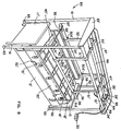
- FIG. 1 an apparatus for lifting and turning a patient according to the present invention is illustrated in Figure 1 and shown generally at reference numeral 10.
- Apparatus 10 is shown mounted on the footboard 11 and headboard 12 of a hospital bed 13 by brackets 14 which are positioned on the top edge of the footboard 11 and headboard 12. Brackets 14 may be attached by bolts, clamps or by other suitable means.
- Bed 13 includes a mattress 15 and vertically adjustable side rails 16 and 17.
- Apparatus 10 is comprised of on open framework which includes upright foot and head standards 19, 20 to which the brackets 14 are secured.
- Winding bars 21 and 22 are mounted in suitable bearings (not shown) and are carried by winding bar supports 23, 24.
- Winding bars 21 and 22 are driven by a motor and gear reduction unit 25 mounted on winding bar support 24.
- Motor and gear reduction unit 25 has a drive sprocket 26 which drives driven sprockets 27 and 28 concentrically mounted on winding bars 21 and 22, respectively by means of a sprocket chain 29.
- a 1650 rpm, 1/6 hp reversible duty single phase motor is reduced through a 40 to 1 gear reduction unit.
- a control box 30 controls operation of the motor 25 and therefore the motion of the winding bars 21 and 22.
- Connecting means comprising first and second pairs of straps 31, 32 are wound onto winding bars 21 and 22 and secured by bolts (not shown) or by similar means. Both pairs of straps 31, 32 are wound in a counter-clockwise direction since motor 25 rotates gears 27 and 28 in the same direction.
- the other end of pairs of straps 31 and 32 are formed into loops 31A, 32A. These loops 31A, 32A receive and support respective spacing bars 33 and 34. Normally, spacing bars 33 and 34 are positioned at or just slightly above the upper surface of mattress 15. Spacing bars 33 and 34 are shown in a slightly elevated position in Figure 1.
- Brace 35 is positioned in holes 37 in the upper side of one foot end of spacing bars 33 and 34, and includes side braces 39 which keep spacing bars 33 and 34 parallel with the winding bars 21 and 22.
- Brace 36 is positioned in holes 38 in the upper side of the head end of spacing bars 33 and 34.
- Patient support means comprise a plurality of thick lambswool covered support straps--in Figure 1 five such straps 40-44 are shown. Either more or fewer straps may be used depending on the size and weight of the patient, the width of the straps and similar factors.
- Each end of the straps 40-44 have complementary male and female hook and loop fasteners 45 (only the male is shown) by which the support straps 40-44 are securely fastened to spacing bars 33 and 34.
- the support straps 40-44 are laterally, i.e., side-to-side, positioned in spaced-apart relation along the length of the mattress 15. The spacing as well as the number of support straps 40-44 is determined by the size of the patient and the width of the support straps 40-44.
- support straps 40-44 are positioned directly beneath the patient, not below the bed sheet, draw sheet or other bed coverings.
- the thick lambswool padding on the support straps 40-44 prevents irritation and, in fact, is more comfortable for the patient than lying flat on the bed 13 without the support straps 40-44.
- Patient turning means are also provided, and comprise a draw sheet 50 centered laterally across bed 13.
- Draw sheet 50 includes a folded loop 51 in each side of the draw sheet 50 into which and through which is positioned a sheet attachment bar 52.
- FIG 8 an apparatus for lifting and turning a patient according to another embodiment of the present invention is illustrated in Figure 8 and shown generally at reference numeral 60.
- elements which have counterparts in the description of apparatus 10 are identified with the same reference numerals.
- Apparatus 60 is a portable unit which can be moved from bed-to-bed, or which can be used to transport a patient from one bed to another or to other facilities.
- Apparatus 60 is comprised of an open framework which includes upright foot and head standards 61, 62 which are mounted on caster wheels 63.
- Standards 61 and 62 are spaced apart sufficiently wide to permit apparatus 60 to be positioned over a bed 13′ by rolling it over the bed from one side.
- an apparatus could be sized to permit it to be rolled over the bed 13′ from the front or rear.
- Bed 13′ includes a footboard 11′, a headboard 12′ mattress 15′ and vertically adjustable side rails 16′ and 17′.
- Winding bars 21′, 22′ which are stationary, and center winding bar 66, which is mounted in suitable bearings (not shown) and are carried by winding bar supports 23′ and 24′.
- Center winding bar 66 is centrally mounted and is driven by motor and gear reduction unit 25′ and in turn drives winding bars 21′ and 22′.
- Motor and gear reduction unit 25′ has a drive sprocket 26′ which drives a driven sprocket 64 by means of a sprocket chain 65.
- Sprocket 64 is mounted on the end of the centrally mounted winding bar 66 for rotation therewith.
- a winding bar support brace 67 is secured to winding bar supports 23′, 24′ by opposite ends and extends the length of the apparatus 60 in order to provide greater stability.
- a 1650 rpm, 1/6 hp reversible duty single phase motor is reduced through a 40 to 1 gear reduction unit.
- the diameter and teeth of the gearing are selected to provide 11 rpm for the winding bar 66.
- many other combinations of motor sizes, powers and drive arrangements are usable with suitable adjustments in gearing.
- a control box 30′ controls operation of the motor and gear reduction unit 25′ and therefore the motion of the winding bars 21′, 22′ and 66.
- Connecting means comprising first and second pairs of straps 31′, 32′ pass over the top of stationary winding bars 21′ and 22′, through nylon rollers, and are connected by one end to the center winding bar 66 by bolts or some equivalent means.
- Straps 31′, 32′ are each wound in a counter-clockwise direction. Is is shown in Figure 8, the straps 31′ wind off of the top of center winding bar 66, while straps 32′ wind off of the bottom of the center winding bar 66.
- operation of motor and gear reduction unit 25′ winds the straps 31′ and 32′ in the same direction notwithstanding that the are attached to the single center winding bar 66.
- pairs of straps 31′ and 32′ are formed into loops 31A′, 32A′. These loops 31A′, 32A′ receive and support respective spacing bars 33′ and 34′. Normally, spacing bars 33′ and 34′ are positioned at or just slightly above the upper surface of mattress 15′. Spacing bars 33′ and 34′ are shown in a slightly elevated position in Figure 1.
- Brace 35′ is positioned in holes 37′ in the upper side of one foot end of spacing bars 33′ and 34′, and includes side braces 39′ which keep spacing bars 33′ and 34′ parallel with the winding bars 21′, 22′ and 66.
- Brace 36′ is positioned in holes 38′ in the upper side of the head end of spacing bars 33′ and 34′.
- Patient support means comprise a plurality of thick lambswool covered support straps--in Figure 8 five such straps 40′-44′ are shown. Either more or fewer straps may be used depending on the size and weight of the patient, the width of the straps and similar factors.
- Each end of the straps 40′-44′ have complementary male and female hook and loop fasteners 45′ (only the male is shown) by which the support straps 40′-44′ are securely fastened to spacing bars 33′ and 34′.
- the support straps 40′-44′ are laterally, i.e., side-to-side, positioned in spaced-apart relation along the length of the mattress 15′.
- the spacing as well as the number of support straps 40′-44′ is determined by the size of the patient and the width of the support straps 40′-44′.
- five support straps will be used for a normal sized adult patient--one each for the head/neck; upper torso, lower torso/buttocks, upper legs and lower legs/feet.
- the support straps 40′-44′ are positioned directly beneath the patient, not below the bed sheet, draw sheet or other bed coverings.
- the thick lambswool padding on the support straps 40′-44′ prevents irritation and, in fact, is more comfortable for the patient than lying flat on the bed 13′ without the support straps 40′-44.′
- the patient can be lifted by activating motor and gear reduction unit 25′ through use of the control box 30′.
- a height detection finger 47′ connected to a limit switch shuts off motor and gear reduction unit 25′ when contacted by brace 36′ to prevent the patient from being lifted too high. Normally, the patient would never need to be lifted more than about 12-15 inches off of the surface of mattress 15.′
- Patient turning means are also provided, and comprise a draw sheet 50′ centered laterally across bed 13′.
- Draw sheet 50′ includes a folded loop 51′ in each side of the draw sheet 50′ into which and through which is positioned a sheet attachment bar 52′.
- apparatus 60 permits a patient to be easily and safely lifted. Since the method is the same with either apparatus 10 or 60, it will be described with reference to Apparatus 10, it being understood the method shown in Figures 9-11 is also described.
- support straps 40-44 are positioned along the length of the bed 13 from side-to-side. They are attached in the manner shown in Figure 3. With the patient lying on top of the support straps 40-44, the patient is lifted as is shown in Figure 4.
- the braces 35 and 36 (not shown for clarity in Figure 4 but shown in Figure 1) keep spacing bars 33 and 34 in the proper spacing as is shown In Figures 3 and 4.
- the bed 13 is furnished with clean bed linens in a conventional manner--not in the manner used to make invalid beds.
- the patient can also be cleaned, undressed and dressed while in this position much more quickly and easily than when lying on the bed 13.
- the support straps 40-44 will themselves be soiled due to incontinence of the patient.
- the support straps 40-44 can be easily replaced with cleans ones by merely providing a second set of support straps 40-44.
- One of the straps of the second set is first attached to the spacing bars 33 and 34 directly adjacent to the one to be replaced.
- the soiled strap for example strap 40 in Figure 4
- the soiled strap is detached from the spacing bars 33 and 34 and removed. This process is repeated until as many of the straps as desired have been removed and replaced.
- the soiled straps can be laundered, and used to replace the other set of straps when they become soiled.
- the support straps 40-44 may be used in other ways as well. Gently removing the strap supporting the patient's head and next while the patient is suspended above the bed permits the patient's hair to be cut and/or washed and dried without wetting or dirtying the bed sheets. With the patient's head above the bed, a plastic protective sheet, basin or other protection can easily be placed under the patient's head.
- Removing the strap supporting the patient's lower legs and feet permits the knee to flex and the foot to hang down. In this position the patient's legs can be exercised or massaged. The feet can be washed, the nails cut or other patient care carried out very conveniently and at a comfortable height for the patient care provider.
- FIGs 5-7 and 12-14 A method of turning a patient is illustrated in Figures 5-7 and 12-14. Since the method is the same with either apparatus 10 or 60, it will be described with reference to Apparatus 10, it being understood the method shown in Figures 12-14 is also described.
- spacing bar 33 is removed from strap 32 and put aside.
- the two straps 32 are extended laterally across the bed 13 to the other side by activating the motor 25 to provide sufficient length for the straps 32 to extend on the diagonal.
- the sheet attachment bar 52 is positioned in loop 51 of draw sheet 50 so that it extends out both ends.
- One of the straps 31 is connected to one end of the sheet attachment bar 52 and the other of the straps 31 is attached to the other end of sheet attachment bar 52. This is done by passing the opposing ends of the sheet attachment bar 52 through the loops 31A on the ends of the two straps 31.
- the support straps 40-44 remain in place under the patient.
- the patient can be turned in the opposite direction by removing spacing bar 34 from the straps 32, extending the straps 32 across the bed in the manner described above, but across the bed in the opposite direction.
- the sheet attachment bar 52 is placed in the loop 51 of the draw sheet 50 on the other side of the bed and the process described above is completed.
- apparatus 10 and apparatus 60 including the standards, winding bars, spacing bars and winding bar supports are fabricated from stainless steel bar or tubing as required.
- the straps 31, 32 and 40-44 are fabricated from heavy-duty webbing of the type used for cargo slings and the like.
Landscapes
- Health & Medical Sciences (AREA)
- Nursing (AREA)
- Life Sciences & Earth Sciences (AREA)
- Animal Behavior & Ethology (AREA)
- General Health & Medical Sciences (AREA)
- Public Health (AREA)
- Veterinary Medicine (AREA)
- Invalid Beds And Related Equipment (AREA)
Abstract
Description
- This invention relates to an apparatus and method for lifting and turning a patient confined to a bed. The ability to easily lift and turn a patient permits the patient to be easily bathed, dressed and undressed, exercised and otherwise cared for in ways which are difficult or impossible when the patient cannot be removed from the bed and therefore must be moved around on the surface of the bed. The ability to lift and suspend the patient above the surface of the bed permits easy and frequent changes of bed linens. These features substantially reduce staff labor and the amount of time required to properly and compassionately attend to a patient's physical and sanitary needs, reduce odors, skin infections and bed sores, and substantially improves the overall level of care which can be provided.
- The apparatus according to the invention is equally adaptable for use in hospitals, nursing homes and in the patient's own home. In fact, the ease with which the patient can be cared for using the apparatus and method of the invention permits many patients to be cared for by their family at home, rather than being confined to a nursing home or hospital.
- Typical procedures used to care for bedridden patients require that the patient be physically moved about on the surface of the bed. For example, care for incontinent patients typically requires that the patient be physically rolled or turned onto one side of the bed. The patient is held in that position manually or with a pillow wedged under the back while the draw sheet, plastic sheet and cloth sheet and even perhaps the mattress pad is removed from that side of the bed and placed next to the patient. Then, fresh bed linens are placed and arranged on the bare side of the bed. The patient is then manually rolled over the dirty linen onto the newly made side of the bed with the fresh linen, while the soiled side of the bed on which the patient was lying is changed. The soiled linen is removed and the clean linen already on the other side is pulled across the bed and arranged. Then, the patient is rolled to the center of the bed. If care is not taken, moving the patient back and forth on the bed while changing the bed linens can re-soil the freshly applied linens if the patient's clothes are themselves soiled--a condition which is very common.
- Bathing patients is also quite difficult while the patient is lying on the bed. Many areas of the body are difficult to reach and properly clean unless the patient is turned or rolled. Constant contact between the patient and the bed almost insures re-soiling of either the patient or the bed linens since both cannot be cleaned at the same time.
- Bedsores and poor blood circulation are common ailments of invalid patients. For this reason, good medical practice requires that a patient be rolled or turned from side-to-side periodically to relieve pressure on particular joints and muscles, and to vary the circulation pattern and permit free circulation to all parts of the body. Since invalid patients can suffocate if rolled over onto their stomach for any period of time, the patient is merely rolled partially so that the patient is lies flat on the back, then on towards one side, then the other side in alternating sequence, the patient being supported by a pillow against the side and under the back. This requires repeated physical labor by the person caring for the patient. Because of the difficulty of doing this, and staff shortages, patients very often are not turned as often as good medical practice requires.
- This procedure is time-consuming and requires substantial physical labor. The amount of labor often requires that two or more persons carry out the steps described above. This often makes it impossible for a patient to be cared for at home even though the condition of the patient is otherwise acceptable for home care. This causes substantial additional health care costs, overcrowding and staff shortages. A recognized cause of the difficulty in hiring non-professional hospital and nursing home staff is the objection many otherwise willing and qualified staff have to the amount of physical labor required to attend to the sanitary needs of bedridden patients.
- It is also documented that one of the significant causes of workers compensation claims and on-the-job inturies in hospitals and nursing homes are strains, muscle pulls and the like resulting from the continuous practice of the procedures described above.
- The apparatus and method of the invention were conceived and developed as the result of a husband's desire to care for his invalid wife at home, and the unavailability of any apparatus to assist in caring for the wife's sanitary needs.
- Therefore, it is an object of the invention to provide an apparatus which permits a bedridden patient to be lifted and suspended above the bed while the bed linens are changed.
- It is another object of the invention to provide an apparatus which permits a bedridden patient to be bathed while suspended above the bed.
- It is another object of the invention to provide an apparatus which permits a bedridden invalid patient to be turned from side-to-side while on the bed.
- It is another object of the invention to provide an apparatus which can be attached to and used with a conventional type of bed.
- It is another object of the invention to provide an apparatus which can be rolled from bed-to-bed or to bathing or other stations with the patient suspended thereon.
- It is another object of the invention to provide an apparatus which can be rolled from bed-to-bed or to bathing or other stations while empty whereby a single apparatus can service numerous patients.
- It is another object of the invention to provide an apparatus which can be integrally formed with a bed.
- It is another object of the invention to provide a method of turning a patient from side-to-side while confined to an invalid bed.
- It is another object of the invention to provide a method of changing bed linens of invalid bed and cleaning a patient while the patient is confined to the invalid bed.
- It is another object of the invention to provide a method of attending to various parts of the patient by selective removal of the means by which the patient is suspended above the bed.
- These and other objects of the present invention are achieved in the preferred embodiments disclosed below by providing an invalid patient lifting and turning apparatus which includes an open framework for being positioned above a bed, elevator means supported by the open framework, and patient support means for being positioned on a mattress of the bed underneath the patient and remaining underneath the patient at all times. The support means comprises a plurality of spaced-apart, removable and replaceable strap means for extending laterally from side-to-side along the length of the patient for supporting the patient's head, trunk and legs. Connecting means are provided for connecting the patient support means and the elevator means thereby permitting the patient support means to lift the patient above the mattress surface for cleaning and bed-linen changing. Patient turning means are provided for being connected to the elevator means for turning the patient from side-to-side in the bed.
- According to one preferred embodiment of the invention, the elevator means includes first and second spaced-apart winding bars extending along the length of the framework, a motor carried by the framework, and drive means operatively interconnecting the motor and the first and second winding bars for rotating the winding bars in opposite winding and unwinding directions.
- According to another preferred embodiment of the invention, the connecting means includes first and second pairs of spaced-apart elongate flexible members connected by one end to respective first and second winding bars and first and second spacing bars positioned on opposite sides of the framework and extending along the length of the framework in longitudinal alignment with the winding bars and connected to the other end of respective ones of the pairs of flexible members.
- According to yet another preferred embodiment of the invention, the patient turning means includes elongate means extending diagonally from one of the winding bars laterally across the framework to the opposite side thereof; and sheet attachment means for being attached to a draw sheet extending under the patient and being pulled diagonally laterally across the bed from one side towards the opposite side of the bed.
- According to one preferred embodiment of the invention, the drive means includes a drive sprocket on the motor and first and second driven sprockets positioned for rotation respectively with the first and second winding bars. An endless chain interconnects the drive sprocket and the first and second driven sprockets for transmitting rotary motion from the motor to the first and second winding bars.
- According to another preferred embodiment of the invention, the drive means includes a third winding bar mounted on the framework between the first and second winding bars and extending along the length of the framework in axial alignment with the first and second winding bars, and first and second straps, each connected by one end thereof to the third winding bar and by the opposite end thereof to respective ones of the first and second winding bars. One of the first and second straps extends around the third winding bar in a clockwise direction and the other of the first and second straps extends around the third winding bar in a counterclockwise direction. Rotation of the motor in one direction winds both first and second straps onto the third winding bar and rotation in the other direction unwinds both the first and second straps off of the third winding bar.
- According to yet another preferred embodiment of the invention, the sheet attachment means comprises a bar for being passed through a loop in the draw sheet and attached to the elongate means.
- According to yet another preferred embodiment of the invention the elongate means comprises a strap.
- An embodiment of the method according to the invention, a method of turning a patient confined to a bed comprises the steps of positioning patient support means laterally across the bed from one side to the other between the bed mattress and the patient, connecting the patient support means on one side of the bed to elongate connecting means extending diagonally and laterally across the bed from a position above the bed and on the side of the patient opposite from the side where the connecting means are attached to the patient support means, and retracting the connecting means diagonally and laterally upwardly away from the patient to pull the support means against the patient whereby the patient is turned.
- Another embodiment according to the invention comprises a method of changing bed linens of an invalid bed and cleaning a patient while the patient is confined to the invalid bed, and comprising the steps of positioning patient support means laterally across the bed from one side to the other between the bed mattress and the patient in direct contact with the patient, lifting the patient support means and the patient thereon to a suspended position in spaced-apart relation to the upper surface of the bed and holding the patient in the suspended position while removing the soiled bed linen and replacing it with clean bed linen and cleaning the patient. Then the cleaned patient is lowered onto,the freshly made bed.
- Preferably, the patient support means comprises a first plurality of strap members extending laterally from side-to-side in spaced-apart relation along the length of the patient for supporting the patient's head, trunk and legs. The method preferably includes the steps of providing a second plurality of strap members, placing one of the second plurality of strap members in place adjacent one of the first plurality of strap members while the patient is in the suspended position and removing the adjacent one of the first plurality of strap members while the patient is in the suspended position and repeating above steps until all or at least the soiled ones of the first plurality of strap members have been replaced with the second plurality of strap members.
- According to one preferred embodiment of the invention, the method includes the step of removing the strap member supporting the patient's head while the patient is in the suspended position in order to wash the patients hair.
- According to one preferred embodiment of the invention, the method includes the step of removing the strap member supporting the patient's lower legs in order to bathe the feet or permit exercise or massage of the lower legs and feet.
- Preferably, the support means comprise straps having a soft, thick intermediate portion for being positioned under the patient and opposing end portions having fastening means for permitting the straps to fastened to elevator means used to lift and suspend the patient.
- Preferably, the intermediate portion comprises lamb or sheep wool and the fastening means comprises cooperating male and female hook and loop fastener components.
- Some of the objects of the invention have been set forth above. Other objects and advantages of the invention will appear as the invention proceeds when taken in conjunction with the following drawings, in which:
- Figure 1 is a perspective view of an apparatus for lifting and turning an invalid patient positioned on a hospital bed;
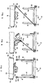
- Figures 2, 3 and 4 are sequential views showing how bed linens are changed by suspending the patient above the bed;
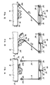
- Figures 5, 6 and 7 are sequential views showing how an invalid patient is turned;
- Figure 8 is a perspective view of an alternative embodiment of an apparatus for lifting and turning an invalid patient which is adapted to be moved from bed-to-bed;
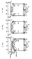
- Figures 9, 10, 11 are sequential views showing how bed linens are changed by suspending the patient above the bed; and
- Figures 12, 13 and 14 are sequential views showing how an invalid patient is turned.
- Referring now specifically to the drawings, an apparatus for lifting and turning a patient according to the present invention is illustrated in Figure 1 and shown generally at
reference numeral 10.Apparatus 10 is shown mounted on the footboard 11 andheadboard 12 of ahospital bed 13 bybrackets 14 which are positioned on the top edge of the footboard 11 andheadboard 12.Brackets 14 may be attached by bolts, clamps or by other suitable means.Bed 13 includes amattress 15 and vertically adjustable side rails 16 and 17. -
Apparatus 10 is comprised of on open framework which includes upright foot andhead standards brackets 14 are secured. Winding bars 21 and 22 are mounted in suitable bearings (not shown) and are carried by winding bar supports 23, 24. Winding bars 21 and 22 are driven by a motor andgear reduction unit 25 mounted on windingbar support 24. Motor andgear reduction unit 25 has adrive sprocket 26 which drives drivensprockets bars sprocket chain 29. In the preferred embodiment a 1650 rpm, 1/6 hp reversible duty single phase motor is reduced through a 40 to 1 gear reduction unit. The diameter and teeth of the gearing are selected to provide 11 rpm for the windingbars control box 30 controls operation of themotor 25 and therefore the motion of the windingbars - Connecting means comprising first and second pairs of
straps bars straps motor 25 rotates gears 27 and 28 in the same direction. The other end of pairs ofstraps loops loops mattress 15. Spacing bars 33 and 34 are shown in a slightly elevated position in Figure 1. - Spacing bars 33 and 34 are maintained in the correct alignment and spacing with each other by means of
braces Brace 35 is positioned inholes 37 in the upper side of one foot end of spacingbars bars bars Brace 36 is positioned inholes 38 in the upper side of the head end of spacingbars - Patient support means comprise a plurality of thick lambswool covered support straps--in Figure 1 five such straps 40-44 are shown. Either more or fewer straps may be used depending on the size and weight of the patient, the width of the straps and similar factors. Each end of the straps 40-44 have complementary male and female hook and loop fasteners 45 (only the male is shown) by which the support straps 40-44 are securely fastened to spacing
bars mattress 15. The spacing as well as the number of support straps 40-44 is determined by the size of the patient and the width of the support straps 40-44. Typically, five support straps will be used for a normal sized adult patient--one each for the head/neck; upper torso, lower torso/buttocks, upper legs and lower legs/feet. The support straps 40-44 are positioned directly beneath the patient, not below the bed sheet, draw sheet or other bed coverings. The thick lambswool padding on the support straps 40-44 prevents irritation and, in fact, is more comfortable for the patient than lying flat on thebed 13 without the support straps 40-44. Once all of the support straps 40-44 are fastened to the spacing bars 33 and 34, the patient can be lifted by activating motor andgear reduction unit 25 through use of thecontrol box 30. Aheight detection finger 47 connected to a limit switch shuts 48 off motor andgear reduction unit 25 when contacted bybrace 36 to prevent the patient from being lifted too high. Normally, the patient would never need to be lifted more than about 12-15 inches off of the surface ofmattress 15. - Patient turning means are also provided, and comprise a
draw sheet 50 centered laterally acrossbed 13.Draw sheet 50 includes a foldedloop 51 in each side of thedraw sheet 50 into which and through which is positioned asheet attachment bar 52. - Referring now to Figure 8, an apparatus for lifting and turning a patient according to another embodiment of the present invention is illustrated in Figure 8 and shown generally at
reference numeral 60. In the text which follows, elements which have counterparts in the description ofapparatus 10 are identified with the same reference numerals. -
Apparatus 60 is a portable unit which can be moved from bed-to-bed, or which can be used to transport a patient from one bed to another or to other facilities.Apparatus 60 is comprised of an open framework which includes upright foot andhead standards caster wheels 63.Standards apparatus 60 to be positioned over abed 13′ by rolling it over the bed from one side. Alternatively, an apparatus could be sized to permit it to be rolled over thebed 13′ from the front or rear.Bed 13′ includes a footboard 11′, aheadboard 12′mattress 15′ and vertically adjustable side rails 16′ and 17′. - Winding bars 21′, 22′ which are stationary, and
center winding bar 66, which is mounted in suitable bearings (not shown) and are carried by winding bar supports 23′ and 24′.Center winding bar 66 is centrally mounted and is driven by motor andgear reduction unit 25′ and in turndrives winding bars 21′ and 22′. Motor andgear reduction unit 25′ has adrive sprocket 26′ which drives a drivensprocket 64 by means of asprocket chain 65.Sprocket 64 is mounted on the end of the centrally mounted windingbar 66 for rotation therewith. - A winding
bar support brace 67 is secured to winding bar supports 23′, 24′ by opposite ends and extends the length of theapparatus 60 in order to provide greater stability. - In the preferred embodiment a 1650 rpm, 1/6 hp reversible duty single phase motor is reduced through a 40 to 1 gear reduction unit. The diameter and teeth of the gearing are selected to provide 11 rpm for the winding
bar 66. Of course, many other combinations of motor sizes, powers and drive arrangements are usable with suitable adjustments in gearing. - A
control box 30′ controls operation of the motor andgear reduction unit 25′ and therefore the motion of the windingbars 21′, 22′ and 66. - Connecting means comprising first and second pairs of
straps 31′, 32′ pass over the top of stationary windingbars 21′ and 22′, through nylon rollers, and are connected by one end to thecenter winding bar 66 by bolts or some equivalent means.Straps 31′, 32′ are each wound in a counter-clockwise direction. Is is shown in Figure 8, thestraps 31′ wind off of the top ofcenter winding bar 66, whilestraps 32′ wind off of the bottom of thecenter winding bar 66. As a result, operation of motor andgear reduction unit 25′ winds thestraps 31′ and 32′ in the same direction notwithstanding that the are attached to the singlecenter winding bar 66. The other end of pairs ofstraps 31′ and 32′ are formed intoloops 31A′, 32A′. Theseloops 31A′, 32A′ receive and support respective spacing bars 33′ and 34′. Normally, spacing bars 33′ and 34′ are positioned at or just slightly above the upper surface ofmattress 15′. Spacing bars 33′ and 34′ are shown in a slightly elevated position in Figure 1. - Spacing bars 33′ and 34′ are maintained in the correct alignment and spacing with each other by means of
braces 35′ and 36′.Brace 35′ is positioned inholes 37′ in the upper side of one foot end of spacingbars 33′ and 34′, and includes side braces 39′ which keep spacingbars 33′ and 34′ parallel with the windingbars 21′, 22′ and 66.Brace 36′ is positioned inholes 38′ in the upper side of the head end of spacingbars 33′ and 34′. - Patient support means comprise a plurality of thick lambswool covered support straps--in Figure 8 five
such straps 40′-44′ are shown. Either more or fewer straps may be used depending on the size and weight of the patient, the width of the straps and similar factors. Each end of thestraps 40′-44′ have complementary male and female hook andloop fasteners 45′ (only the male is shown) by which the support straps 40′-44′ are securely fastened to spacingbars 33′ and 34′. - As is shown in Figure 8, the support straps 40′-44′ are laterally, i.e., side-to-side, positioned in spaced-apart relation along the length of the
mattress 15′. The spacing as well as the number of support straps 40′-44′ is determined by the size of the patient and the width of the support straps 40′-44′. Typically, five support straps will be used for a normal sized adult patient--one each for the head/neck; upper torso, lower torso/buttocks, upper legs and lower legs/feet. The support straps 40′-44′ are positioned directly beneath the patient, not below the bed sheet, draw sheet or other bed coverings. The thick lambswool padding on the support straps 40′-44′ prevents irritation and, in fact, is more comfortable for the patient than lying flat on thebed 13′ without the support straps 40′-44.′ Once all of the support straps 40-44′ are fastened to the spacing bars 33′ and 34′, the patient can be lifted by activating motor andgear reduction unit 25′ through use of thecontrol box 30′. Aheight detection finger 47′ connected to a limit switch shuts off motor andgear reduction unit 25′ when contacted bybrace 36′ to prevent the patient from being lifted too high. Normally, the patient would never need to be lifted more than about 12-15 inches off of the surface of mattress 15.′ - Patient turning means are also provided, and comprise a
draw sheet 50′ centered laterally acrossbed 13′.Draw sheet 50′ includes a foldedloop 51′ in each side of thedraw sheet 50′ into which and through which is positioned asheet attachment bar 52′. - Use of the
apparatus 60 permits a patient to be easily and safely lifted. Since the method is the same with eitherapparatus Apparatus 10, it being understood the method shown in Figures 9-11 is also described. - As is shown in Figures 1 and 2, support straps 40-44 are positioned along the length of the
bed 13 from side-to-side. They are attached in the manner shown in Figure 3. With the patient lying on top of the support straps 40-44, the patient is lifted as is shown in Figure 4. Thebraces 35 and 36 (not shown for clarity in Figure 4 but shown in Figure 1) keep spacingbars - In this position, the
draw sheet 50 and the other bed linens can easily removed without further moving the patient. Thebed 13 is furnished with clean bed linens in a conventional manner--not in the manner used to make invalid beds. The patient can also be cleaned, undressed and dressed while in this position much more quickly and easily than when lying on thebed 13. - Very often the support straps 40-44 will themselves be soiled due to incontinence of the patient. The support straps 40-44 can be easily replaced with cleans ones by merely providing a second set of support straps 40-44. One of the straps of the second set is first attached to the spacing bars 33 and 34 directly adjacent to the one to be replaced. Then the soiled strap, for
example strap 40 in Figure 4, is detached from the spacing bars 33 and 34 and removed. This process is repeated until as many of the straps as desired have been removed and replaced. Then the soiled straps can be laundered, and used to replace the other set of straps when they become soiled. - The support straps 40-44 may be used in other ways as well. Gently removing the strap supporting the patient's head and next while the patient is suspended above the bed permits the patient's hair to be cut and/or washed and dried without wetting or dirtying the bed sheets. With the patient's head above the bed, a plastic protective sheet, basin or other protection can easily be placed under the patient's head.
- Removing the strap supporting the patient's lower legs and feet permits the knee to flex and the foot to hang down. In this position the patient's legs can be exercised or massaged. The feet can be washed, the nails cut or other patient care carried out very conveniently and at a comfortable height for the patient care provider.
- A method of turning a patient is illustrated in Figures 5-7 and 12-14. Since the method is the same with either
apparatus Apparatus 10, it being understood the method shown in Figures 12-14 is also described. To begin the process, spacingbar 33 is removed fromstrap 32 and put aside. As is shown in Figure 5, the twostraps 32 are extended laterally across thebed 13 to the other side by activating themotor 25 to provide sufficient length for thestraps 32 to extend on the diagonal. Thesheet attachment bar 52 is positioned inloop 51 ofdraw sheet 50 so that it extends out both ends. One of thestraps 31 is connected to one end of thesheet attachment bar 52 and the other of thestraps 31 is attached to the other end ofsheet attachment bar 52. This is done by passing the opposing ends of thesheet attachment bar 52 through theloops 31A on the ends of the twostraps 31. The support straps 40-44 remain in place under the patient. - With the
apparatus 10 configured as described above,motor 25 is activated and thestraps 31 are wound onto the windingbar 21. As is shown in Figure 6,draw sheet 50 is pulled against the patient from the side of thebed 13 opposite the windingbar 21. Is the patient is rolled, a pillow is chocked under the patient to maintain the patient in the turned position. With the patient properly turned and repositioned, straps 31 are removed from the sheet attachment bar and repositioned to support thespacing bar 33, as is shown in Figure 7. - The patient can be turned in the opposite direction by removing
spacing bar 34 from thestraps 32, extending thestraps 32 across the bed in the manner described above, but across the bed in the opposite direction. Thesheet attachment bar 52 is placed in theloop 51 of thedraw sheet 50 on the other side of the bed and the process described above is completed. - The structure of
apparatus 10 andapparatus 60, including the standards, winding bars, spacing bars and winding bar supports are fabricated from stainless steel bar or tubing as required. Thestraps - An apparatus for lifting and turning a patient is described above. Various details of the invention may be changed without departing from its scope. Furthermore, the foregoing description of the preferred embodiment of the invention and the best mode for practicing the invention are provided for the purpose of illustration only and not for the purpose of limitation--the invention being defined by the claims.
Claims (15)
- An invalid patient lifting and turning apparatus, comprising:(a) an open framework for being positioned above a bed;(b) elevator means supported by said open framework;(c) patient support means for being positioned on a mattress of the bed underneath the patient and remaining underneath the patient at all times, said support means comprising a plurality of spaced-apart, removable and replaceable support strap means for extending laterally from bide-to-side along the length of the patient for supporting the patient's head, trunk and legs;(d) connecting means for connecting the patient support means and said elevator means thereby permitting the patient support means to lift the patient above the mattress surface for cleaning and bed-linen changing; and(e) patient turning means for being connected to said elevator means for turning the patient from side-to-side in the bed.
- A lifting and turning apparatus according to claim 1, wherein said elevator means comprises:(a) first and second spaced-apart winding bars extending along the length of the framework;(b) a motor carried by said framework; and(c) drive means operatively interconnecting said motor and said first and second winding bars for rotating said winding bars in opposite winding and unwinding directions.
- A lifting and turning apparatus according to claim 2, wherein said connecting means comprises:(a) first and second pairs of spaced-apart elongate flexible members connected by one end to respective first and second winding bars; and(b) first and second spacing bars positioned on opposite bides of said framework and extending along the length of the framework in longitudinal alignment with said winding bars and connected to the other end of respective ones of said pairs of flexible members.
- A lifting and turning apparatus according to claim 3, wherein said patient turning means comprises:(a) elongate means extending diagonally from one of said winding barb laterally across the framework to the opposite bide thereof; and(b) sheet attachment means for being attached to a draw sheet means extending under the patient and being pulled diagonally laterally across the bed from one bide towards the opposite bide of the bed.
- A lifting and turning apparatus according to claim 2, wherein said drive means comprises:(a) a drive sprocket on said motor;(b) first and second driven sprockets positioned for rotation respectively with said first and second winding bars; and(c) an endless chain interconnecting said drive sprocket and said first and second driven sprockets for transmitting rotary motion from said motor to said first and second winding bars.
- A lifting and turning apparatus according to claim 2, wherein maid drive means comprises:(a) a third winding bar mounted on said framework between said first and second winding bars and extending along the length of the framework in axial alignment with said first and second winding bars;(c) first and second straps, each connected by one end thereof to said third winding bar and by the opposite end thereof to respective ones of the first and second spacing bars;(d) one of said first and second straps extending around said third winding bar in a clockwise direction and the other of said first and second straps extending around said third winding bar in a counterclockwise direction whereby rotation of said motor in one direction winds both first and second straps onto said third winding bar and rotation in the other direction unwinds both the first and second straps off of said third winding bar.
- A lifting and turning apparatus according to claim 4, wherein said sheet attachment means comprises a bar for being passed through a loop in the draw sheet and attached to said elongate means.
- A lifting and turning apparatus according to claim 7, wherein said elongate means comprises a strap.
- A method of turning a patient from bide-to-side while confined to an invalid bed, and comprising the steps of:(a) positioning patient support means laterally across the bed from one bide to the other between the bed mattress and the patient;(b) connecting the patient support means on one bide of the bed to elongate connecting means extending diagonally and laterally across the bed from a position above the bed and on the bide of the patient opposite from the bide where the connecting means are attached to the patient support means; and(c) retracting the connecting means diagonally and laterally upwardly away from the patient to pull the support means against the patient whereby the patient is turned.
- A method of changing bed linens of invalid bed and cleaning a patient while the patient is confined to the invalid bed, and comprising the steps of:(a) positioning patient support means laterally across the bed from one bide to the other between the bed mattress and the patient in direct contact with the patient;(b) lifting the patient support means and the patient thereon to a suspended position in spaced-apart relation to the upper surface of the bed and holding the patient in the suspended position during the following steps (c)-(d);(c) removing the soiled bed linen and replacing it with clean bed linen;(d) cleaning the patient;(e) lowering the cleaned patient onto the freshly made bed.
- A method according to claim 10, wherein said patient support means comprises a first plurality of strap members extending laterally from side-to-side in spaced-apart relation along the length of the patient for supporting the patient's head, trunk and legs, and said method includes the steps of:(f) providing a second plurality of strap members;(g) placing one of the second plurality of strap members in place adjacent one of the first plurality of strap members while the patient is in the suspended position;(h) removing the adjacent one of the first plurality of strap members while the patient is in the suspended position;(i) repeating steps (g) and (h) the desired ones of the first plurality of strap members have been replaced with the second plurality of strap members.
- A method according to claim 11, and including the step of removing the strap member supporting the patient's head while the patient is in the suspended position in order to wash the patient's hair.
- A method according to claim 11, and including the step of removing the strap member supporting the patient's lower legs in order to bathe the feet or permit exercise or massage of the lower legs and feet.
- A method according to claim 10, wherein said support means comprise straps having a soft, thick intermediate portion for being positioned, under the patient and opposing end portions having fastening means for permitting the straps to fastened to elevator means used to lift and suspend the patient.
- A method according to claim 14 wherein said intermediate portion comprises lamb or sheep wool, and said fastening means comprises cooperating male and female hook and loop fastener components.
Applications Claiming Priority (2)
| Application Number | Priority Date | Filing Date | Title |
|---|---|---|---|
| US718971 | 1991-06-21 | ||
| US07/718,971 US5068931A (en) | 1991-06-21 | 1991-06-21 | Apparatus for lifting and turning a patient confined to a bed |
Publications (3)
| Publication Number | Publication Date |
|---|---|
| EP0519735A2 true EP0519735A2 (en) | 1992-12-23 |
| EP0519735A3 EP0519735A3 (en) | 1993-02-03 |
| EP0519735B1 EP0519735B1 (en) | 1996-02-28 |
Family
ID=24888289
Family Applications (1)
| Application Number | Title | Priority Date | Filing Date |
|---|---|---|---|
| EP92305641A Expired - Lifetime EP0519735B1 (en) | 1991-06-21 | 1992-06-19 | Apparatus and method for lifting and turning a patient confined to a bed |
Country Status (6)
| Country | Link |
|---|---|
| US (2) | US5068931A (en) |
| EP (1) | EP0519735B1 (en) |
| AU (1) | AU647939B2 (en) |
| CA (1) | CA2071571C (en) |
| DE (1) | DE69208534D1 (en) |
| NZ (1) | NZ243208A (en) |
Cited By (5)
| Publication number | Priority date | Publication date | Assignee | Title |
|---|---|---|---|---|
| WO1993014732A1 (en) * | 1992-01-27 | 1993-08-05 | Lahtinen Veli Tapani | Lifting device for sick or motion-handicapped person |
| WO2006061606A1 (en) * | 2004-12-08 | 2006-06-15 | Allan Richard James | System for turning a patient |
| GB2439918A (en) * | 2006-07-11 | 2008-01-16 | David Vincent | Bed with vertically lifting patient support |
| EP3117815A1 (en) * | 2015-07-17 | 2017-01-18 | Chung, Tai-Tien | Pull-type body turning aid |
| EP3424478A1 (en) | 2017-07-07 | 2019-01-09 | Hill-Rom Services, Inc. | Patient turning apparatus and method |
Families Citing this family (85)
| Publication number | Priority date | Publication date | Assignee | Title |
|---|---|---|---|---|
| US5155874A (en) * | 1991-08-26 | 1992-10-20 | Juanita Kershaw | Turn sheet for invalid |
| US5168587A (en) * | 1992-05-18 | 1992-12-08 | Shutes Robert S | Patient positioning device |
| US5280657A (en) * | 1992-09-24 | 1994-01-25 | Stagg Marjorie H | Sheet position adjustment assembly and method |
| JP2527131B2 (en) * | 1993-02-04 | 1996-08-21 | 芳夫 浅川 | Body support and bed apparatus using the body support |
| US5265296A (en) * | 1993-04-12 | 1993-11-30 | Ahsan Abbas | Automatic disposable under pad apparatus |
| US5544371A (en) * | 1993-04-13 | 1996-08-13 | Fuller; Carmel U. | Bed patient turning, lifting and transporting apparatus with mobile, folding and knockdown frame |
| US5499408A (en) * | 1994-09-09 | 1996-03-19 | Nix; John W. | Apparatus for lifting invalids |
| US6772456B2 (en) | 1995-09-13 | 2004-08-10 | Hill-Rom Services, Inc. | Portable device for patient pullup, rollover, and transfer and methods thereof |
| US5673443A (en) * | 1996-08-30 | 1997-10-07 | Marmor; Maxine S. | Apparatus for turning a patient in bed |
| US6393636B1 (en) | 1997-12-23 | 2002-05-28 | Basil W. Wheeler | Patient rotation system |
| US5946748A (en) * | 1998-02-17 | 1999-09-07 | Wang; Yi-Lung | Multipurpose body-turn-over apparatus |
| US6026811A (en) * | 1998-03-12 | 2000-02-22 | Settle; Romaine A. | Protective cover for nasal air supply hose |
| US6006376A (en) * | 1998-04-03 | 1999-12-28 | Williamson; Ted | Patient lifting and transport apparatus and method |
| US6098216A (en) * | 1998-10-28 | 2000-08-08 | Theodore A. Williamson | Convertible patient transport apparatus and method of transporting a patient |
| JP4210721B2 (en) * | 1998-11-06 | 2009-01-21 | 清 高浦 | Nursing bed |
| ATE260628T1 (en) * | 1999-06-30 | 2004-03-15 | Yih-Long Wang | MULTIPURPOSE APPARATUS FOR TURNING PATIENTS |
| EP1517662B1 (en) | 2002-06-17 | 2009-07-29 | Hill-Rom Services, Inc. | Apparatus for pulling patient up in bed |
| CA2518160A1 (en) | 2003-03-18 | 2004-09-30 | Hill-Rom Services, Inc. | Radial arm system for patient care equipment |
| US6799342B1 (en) | 2003-05-27 | 2004-10-05 | Robert G. Jarmon | Method and apparatus for supporting a body |
| US7290299B2 (en) | 2004-01-09 | 2007-11-06 | Votel Thomas W | Device and method for positioning patients |
| US7725964B2 (en) | 2004-08-27 | 2010-06-01 | Hill-Rom Services, Inc. | Apparatus with patient adjustment device coupled to architectural system |
| US7487558B2 (en) * | 2004-12-23 | 2009-02-10 | Hill-Rom Services, Inc. | Headboard for a pull-up-in-bed system |
| US9468576B2 (en) | 2005-02-22 | 2016-10-18 | Roger P. Jackson | Patient support apparatus with body slide position digitally coordinated with hinge angle |
| US9186291B2 (en) | 2005-02-22 | 2015-11-17 | Roger P. Jackson | Patient positioning support structure with trunk translator |
| US7152261B2 (en) | 2005-02-22 | 2006-12-26 | Jackson Roger P | Modular multi-articulated patient support system |
| US7739762B2 (en) | 2007-10-22 | 2010-06-22 | Mizuho Orthopedic Systems, Inc. | Surgery table apparatus |
| US9265679B2 (en) | 2005-02-22 | 2016-02-23 | Roger P Jackson | Cantilevered patient positioning support structure |
| US20150059094A1 (en) | 2005-02-22 | 2015-03-05 | Roger P. Jackson | Patient positioning support structure |
| US9744087B2 (en) | 2005-02-22 | 2017-08-29 | Roger P. Jackson | Patient support apparatus with body slide position digitally coordinated with hinge angle |
| US9308145B2 (en) | 2005-02-22 | 2016-04-12 | Roger P. Jackson | Patient positioning support structure |
| US9301897B2 (en) | 2005-02-22 | 2016-04-05 | Roger P. Jackson | Patient positioning support structure |
| US7565708B2 (en) | 2005-02-22 | 2009-07-28 | Jackson Roger P | Patient positioning support structure |
| US9295433B2 (en) | 2005-02-22 | 2016-03-29 | Roger P. Jackson | Synchronized patient elevation and positioning apparatus for use with patient positioning support systems |
| US8707484B2 (en) | 2005-02-22 | 2014-04-29 | Roger P. Jackson | Patient positioning support structure |
| US8407831B2 (en) * | 2006-04-12 | 2013-04-02 | Ergonurse, Inc. | Patient positioning apparatus |
| US7434278B2 (en) * | 2005-06-29 | 2008-10-14 | Elizabeth Ann White | Apparatus for patient mobility |
| US20080301873A1 (en) * | 2005-06-29 | 2008-12-11 | White Elizabeth A | Patient Positioning apparatus |
| WO2007051228A1 (en) * | 2005-11-02 | 2007-05-10 | Kenneth Lindsay Pagden | Sanitary care bed for bedfast patients |
| US20080216232A1 (en) * | 2006-04-12 | 2008-09-11 | White Elizabeth A | Patient Repositioning System |
| US9642760B2 (en) | 2006-05-05 | 2017-05-09 | Roger P. Jackson | Patient positioning support apparatus with virtual pivot-shift pelvic pads, upper body stabilization and fail-safe table attachment mechanism |
| US9339430B2 (en) | 2006-05-05 | 2016-05-17 | Roger P. Jackson | Patient positioning support apparatus with virtual pivot-shift pelvic pads, upper body stabilization and fail-safe table attachment mechanism |
| US10869798B2 (en) | 2006-05-05 | 2020-12-22 | Warsaw Orthopedic, Inc. | Patient positioning support apparatus with virtual pivot-shift pelvic pads, upper body stabilization and fail-safe table attachment mechanism |
| WO2008029357A2 (en) * | 2006-09-06 | 2008-03-13 | Universite De Lausanne | Device for lifting and transferring bodies |
| AU2008213677A1 (en) | 2007-02-06 | 2008-08-14 | Glumetrics, Inc. | Optical systems and methods for rationmetric measurement of blood glucose concentration |
| JP5517919B2 (en) | 2007-05-10 | 2014-06-11 | グルメトリクス、 インク. | Balanced non-consumable fluorescent sensor for immediate intravascular glucose measurement |
| JP5258883B2 (en) * | 2007-07-08 | 2013-08-07 | バスカール ヴィサール パトワーダン | Patient bed with wheelchair and wheelchair |
| WO2009067626A1 (en) | 2007-11-21 | 2009-05-28 | Glumetrics, Inc. | Use of an equilibrium intravascular sensor to achieve tight glycemic control |
| WO2009129186A2 (en) | 2008-04-17 | 2009-10-22 | Glumetrics, Inc. | Sensor for percutaneous intravascular deployment without an indwelling cannula |
| WO2010091375A1 (en) * | 2009-02-09 | 2010-08-12 | Lee Laura W | Patient turning system and method |
| US8302221B1 (en) | 2009-03-03 | 2012-11-06 | Pivot Assist, Llc | Medical assist device with lift seat |
| US8261380B2 (en) * | 2009-06-12 | 2012-09-11 | Bedlab, Llc | Stretcher accessory for turning a patient |
| EP2483679A4 (en) | 2009-09-30 | 2013-04-24 | Glumetrics Inc | Sensors with thromboresistant coating |
| US8467843B2 (en) | 2009-11-04 | 2013-06-18 | Glumetrics, Inc. | Optical sensor configuration for ratiometric correction of blood glucose measurement |
| DE102010037658A1 (en) * | 2010-09-20 | 2012-03-22 | Maquet Gmbh & Co. Kg | Device for lifting and turning a patient |
| WO2013058806A1 (en) | 2011-10-17 | 2013-04-25 | Jackson Roger P | Patient positioning support structure |
| US9561145B2 (en) * | 2012-02-07 | 2017-02-07 | Roger P. Jackson | Fail-safe release mechanism for use with patient positioning support apparati |
| US9498397B2 (en) | 2012-04-16 | 2016-11-22 | Allen Medical Systems, Inc. | Dual column surgical support system |
| US8572774B1 (en) | 2012-05-18 | 2013-11-05 | Michael P. Osika | Apparatus for moving a limb of a bedridden person |
| US12011399B2 (en) | 2013-08-28 | 2024-06-18 | Warsaw Orthopedic, Inc. | Patient positioning support apparatus with fail-safe connector attachment mechanism |
| JP2015100480A (en) * | 2013-11-22 | 2015-06-04 | 林金属工業株式会社 | Nursing bed and nursing auxiliary mechanism |
| US9622928B2 (en) | 2014-07-07 | 2017-04-18 | Roger P. Jackson | Radiolucent hinge for a surgical table |
| US9402775B2 (en) | 2014-07-07 | 2016-08-02 | Roger P. Jackson | Single and dual column patient positioning and support structure |
| JP6351835B2 (en) * | 2014-09-19 | 2018-07-04 | コリア インスティテュート オブ インダストリアル テクノロジーKorea Institute Of Industrial Technology | Body levitation device for bed |
| US10492973B2 (en) | 2015-01-05 | 2019-12-03 | Allen Medical Systems, Inc. | Dual modality prone spine patient support apparatuses |
| US9308393B1 (en) | 2015-01-15 | 2016-04-12 | Dri-Em, Inc. | Bed drying device, UV lights for bedsores |
| CN104739607B (en) * | 2015-04-21 | 2017-03-22 | 童春平 | Multifunctional critical care system |
| AR100164A1 (en) * | 2015-04-23 | 2016-09-14 | Horacio Capilla Jorge | INTRAHOSPITAL VEHICLE TO TRANSFER AND TRANSFER OBES PATIENTS |
| EP3108866B1 (en) | 2015-06-24 | 2019-10-30 | Hill-Rom S.A.S. | Patient positioning apparatus and method |
| US10561559B2 (en) | 2015-10-23 | 2020-02-18 | Allen Medical Systems, Inc. | Surgical patient support system and method for lateral-to-prone support of a patient during spine surgery |
| US10363189B2 (en) | 2015-10-23 | 2019-07-30 | Allen Medical Systems, Inc. | Surgical patient support for accommodating lateral-to-prone patient positioning |
| CN105434125B (en) * | 2016-01-31 | 2018-06-12 | 北京聚精瑞生医疗科技有限公司 | Self-service turn guardrail and pad and its application method |
| US10548793B2 (en) | 2016-06-14 | 2020-02-04 | Allen Medical Systems, Inc. | Pinless loading for spine table |
| US11213448B2 (en) | 2017-07-31 | 2022-01-04 | Allen Medical Systems, Inc. | Rotation lockout for surgical support |
| CN108143562A (en) * | 2018-02-12 | 2018-06-12 | 王灵 | Multifunctional medical axle position turn-over device |
| US11202731B2 (en) | 2018-02-28 | 2021-12-21 | Allen Medical Systems, Inc. | Surgical patient support and methods thereof |
| US11554066B2 (en) * | 2018-05-07 | 2023-01-17 | Spectrum Health Innovations, LLC | Patient slider device |
| US11471354B2 (en) | 2018-08-30 | 2022-10-18 | Allen Medical Systems, Inc. | Patient support with selectable pivot |
| CN211797334U (en) * | 2018-08-31 | 2020-10-30 | 希尔-罗姆服务公司 | Patient rotation system |
| US11707393B2 (en) * | 2020-02-19 | 2023-07-25 | Liko Research & Development Ab | Methods of preparing a subject for rotation and rotating a subject using an overhead lift |
| CN111374844B (en) * | 2020-05-19 | 2024-12-17 | 邵阳学院 | Household sickbed convenient for changing bed sheet |
| US11717456B2 (en) * | 2020-05-20 | 2023-08-08 | Liko Research & Development Ab | Support harnesses, systems, and kits for lifting and/or rotating a subject using an overhead lift |
| US11357685B2 (en) * | 2020-10-29 | 2022-06-14 | Melior Motus Inc. | Apparatus and method for reorienting a person |
| CN113768709B (en) * | 2021-09-22 | 2022-09-06 | 青岛大学附属医院 | Multi-functional nursing bed of urological department |
| CN115105322B (en) * | 2022-06-23 | 2024-05-28 | 北京华商慧智居家养老服务有限公司 | Device and method for shifting, turning over and replacing bedding for disabled person |
| US12599526B2 (en) | 2023-06-30 | 2026-04-14 | Allen Medical Systems, Inc. | Surgical support system with support top height adjustment |
Family Cites Families (30)
| Publication number | Priority date | Publication date | Assignee | Title |
|---|---|---|---|---|
| US545741A (en) * | 1895-09-03 | Device for lifting invalids | ||
| BE525487A (en) * | ||||
| US680814A (en) * | 1900-12-19 | 1901-08-20 | Patrick C Smith | Invalid's bed. |
| US775520A (en) * | 1903-12-07 | 1904-11-22 | Julius W Crigler | Invalid-bed. |
| US801885A (en) * | 1905-04-18 | 1905-10-17 | Elie Lambotte | Antisore mattress. |
| US904587A (en) * | 1907-08-08 | 1908-11-24 | Elias A Wible | Invalid's bed. |
| US936107A (en) * | 1908-07-24 | 1909-10-05 | Robert L Floyd | Mechanism for elevating invalids. |
| GB191404795A (en) * | 1914-02-24 | 1915-05-06 | Hospitals & General Contracts | Improvements in Invalid Lifting Devices for Beds. |
| US1273600A (en) * | 1914-11-23 | 1918-07-23 | Floyd Invalid Lifter Company | Mechanism for lifting and turning invalids. |
| US1227301A (en) * | 1915-01-06 | 1917-05-22 | William Clark Ogden | Invalid-carrier. |
| US1263611A (en) * | 1916-11-04 | 1918-04-23 | Jethro W Scroggin | Surgical and bathing apparatus. |
| US1301284A (en) * | 1918-05-08 | 1919-04-22 | Josiah Ledan | Lifting device. |
| US1459112A (en) * | 1922-02-23 | 1923-06-19 | Charles F Mehl | Invalid bed |
| US1588573A (en) * | 1925-08-24 | 1926-06-15 | Simon C Edmiston | Hospital lift for invalids |
| US1968477A (en) * | 1931-02-18 | 1934-07-31 | Herman E Cole | Invalid hoist |
| US2035116A (en) * | 1934-08-16 | 1936-03-24 | Mitchell John H | Invalid carrier |
| US2100663A (en) * | 1935-08-15 | 1937-11-30 | Robert D Maddox | Invalid lifter |
| US2283511A (en) * | 1941-03-07 | 1942-05-19 | Sellers Ira | Invalid lifting device |
| US2604638A (en) * | 1947-03-05 | 1952-07-29 | Lewis P Furry | Mobile bathing and lift apparatus |
| DE806989C (en) * | 1948-10-02 | 1951-06-21 | Elektro Therapie M B H Ges | Elevating and lowering bed for medical baths |
| US2603851A (en) * | 1950-05-01 | 1952-07-22 | Hawkins Electro Lift Co | Prone body hoist |
| US2629108A (en) * | 1950-10-25 | 1953-02-24 | Harold A Wickey | Invalid handling apparatus |
| GB850516A (en) * | 1955-11-03 | 1960-10-05 | Fredrik Christian Thiis | Improvements in or relating to beds |
| US3383717A (en) * | 1967-03-03 | 1968-05-21 | Opal M Underwood | Bed device for moving patients |
| ES356447A1 (en) * | 1968-07-24 | 1970-07-01 | Carrancio Revuelta | A system for elevation and clinical suspension of patients or accidents. (Machine-translation by Google Translate, not legally binding) |
| DE2623933B2 (en) * | 1976-05-28 | 1980-02-07 | Burdosa Ing. Herwig Burgert, 6300 Giessen | Procedure for repositioning a patient |
| GB2057864B (en) * | 1979-07-17 | 1984-02-15 | Morrison D | Baths for the infirm etc |
| US4742587A (en) * | 1986-04-27 | 1988-05-10 | Dove Arthur J | Medical stretcher |
| US4779296A (en) * | 1987-10-20 | 1988-10-25 | Bond Helen I | Limb supporting device |
| US4872226A (en) * | 1988-06-06 | 1989-10-10 | Robert Lonardo | Means for positioning bedfast patients |
-
1991
- 1991-06-21 US US07/718,971 patent/US5068931A/en not_active Expired - Lifetime
- 1991-12-02 US US07/801,641 patent/US5161267A/en not_active Expired - Lifetime
-
1992
- 1992-06-18 CA CA002071571A patent/CA2071571C/en not_active Expired - Fee Related
- 1992-06-18 NZ NZ243208A patent/NZ243208A/en unknown
- 1992-06-19 EP EP92305641A patent/EP0519735B1/en not_active Expired - Lifetime
- 1992-06-19 AU AU18439/92A patent/AU647939B2/en not_active Ceased
- 1992-06-19 DE DE69208534T patent/DE69208534D1/en not_active Expired - Lifetime
Cited By (8)
| Publication number | Priority date | Publication date | Assignee | Title |
|---|---|---|---|---|
| WO1993014732A1 (en) * | 1992-01-27 | 1993-08-05 | Lahtinen Veli Tapani | Lifting device for sick or motion-handicapped person |
| WO2006061606A1 (en) * | 2004-12-08 | 2006-06-15 | Allan Richard James | System for turning a patient |
| GB2428565A (en) * | 2004-12-08 | 2007-02-07 | Allan Richard James | Systems for turning a patient |
| GB2428565B (en) * | 2004-12-08 | 2007-04-25 | Allan Richard James | Systems for turning a patient |
| JP2008522698A (en) * | 2004-12-08 | 2008-07-03 | ジェームズ,アラン,リチャード | Patient rollover device |
| GB2439918A (en) * | 2006-07-11 | 2008-01-16 | David Vincent | Bed with vertically lifting patient support |
| EP3117815A1 (en) * | 2015-07-17 | 2017-01-18 | Chung, Tai-Tien | Pull-type body turning aid |
| EP3424478A1 (en) | 2017-07-07 | 2019-01-09 | Hill-Rom Services, Inc. | Patient turning apparatus and method |
Also Published As
| Publication number | Publication date |
|---|---|
| EP0519735A3 (en) | 1993-02-03 |
| CA2071571C (en) | 1997-07-15 |
| US5161267A (en) | 1992-11-10 |
| AU1843992A (en) | 1993-01-28 |
| AU647939B2 (en) | 1994-03-31 |
| DE69208534D1 (en) | 1996-04-04 |
| EP0519735B1 (en) | 1996-02-28 |
| US5068931A (en) | 1991-12-03 |
| NZ243208A (en) | 1995-04-27 |
| CA2071571A1 (en) | 1992-12-22 |
Similar Documents
| Publication | Publication Date | Title |
|---|---|---|
| US5161267A (en) | Method for lifting and turning a patient confined to a bed | |
| US5235712A (en) | Apparatus for bathing a patient confined to a bed | |
| US4446587A (en) | Patient positioning device | |
| US4843665A (en) | Patient transport and bed comfort aid | |
| US4536903A (en) | Device for manipulating invalid bed patients | |
| US6560793B2 (en) | Single attendant patient repositioning and care device | |
| US5239713A (en) | Hospital bed | |
| US4675925A (en) | Device for manipulating bedridden patients | |
| US4941220A (en) | Patient care and transfer arrangement | |
| US5390379A (en) | Person conveyor | |
| US2502752A (en) | Head and limb rest | |
| US5584082A (en) | Convertible gurney | |
| US5315723A (en) | Portable patient turning and lifting apparatus | |
| CN114795715A (en) | Rehabilitation nursing bed | |
| WO2011067594A1 (en) | Inflatable member for rotating sleep surface transfer system | |
| US10258523B2 (en) | Patient turning apparatus and methods for use | |
| US5396669A (en) | Transfer and nursing system for a patient | |
| CN110496004A (en) | a nursing device | |
| JP3433313B2 (en) | Bedsore prevention and bathing bed | |
| JPH06209970A (en) | Care lift | |
| JPH11253511A (en) | Caring sheet, and independent walk supporting machine to which caring sheet is engaged | |
| EP4686463A1 (en) | Stretcher with straps and a lift for bedridden patients | |
| JPS60241439A (en) | Patient lift apparatus | |
| JPH0619723U (en) | Care aid | |
| JPH0446745Y2 (en) |
Legal Events
| Date | Code | Title | Description |
|---|---|---|---|
| PUAI | Public reference made under article 153(3) epc to a published international application that has entered the european phase |
Free format text: ORIGINAL CODE: 0009012 |
|
| PUAL | Search report despatched |
Free format text: ORIGINAL CODE: 0009013 |
|
| AK | Designated contracting states |
Kind code of ref document: A2 Designated state(s): CH DE FR GB LI |
|
| AK | Designated contracting states |
Kind code of ref document: A3 Designated state(s): CH DE FR GB LI |
|
| 17P | Request for examination filed |
Effective date: 19930713 |
|
| 17Q | First examination report despatched |
Effective date: 19941006 |
|
| GRAA | (expected) grant |
Free format text: ORIGINAL CODE: 0009210 |
|
| AK | Designated contracting states |
Kind code of ref document: B1 Designated state(s): CH DE FR GB LI |
|
| PG25 | Lapsed in a contracting state [announced via postgrant information from national office to epo] |
Ref country code: LI Effective date: 19960228 Ref country code: FR Effective date: 19960228 Ref country code: CH Effective date: 19960228 |
|
| REF | Corresponds to: |
Ref document number: 69208534 Country of ref document: DE Date of ref document: 19960404 |
|
| PG25 | Lapsed in a contracting state [announced via postgrant information from national office to epo] |
Ref country code: DE Effective date: 19960529 |
|
| PG25 | Lapsed in a contracting state [announced via postgrant information from national office to epo] |
Ref country code: GB Effective date: 19960619 |
|
| EN | Fr: translation not filed | ||
| REG | Reference to a national code |
Ref country code: CH Ref legal event code: PL |
|
| PLBE | No opposition filed within time limit |
Free format text: ORIGINAL CODE: 0009261 |
|
| STAA | Information on the status of an ep patent application or granted ep patent |
Free format text: STATUS: NO OPPOSITION FILED WITHIN TIME LIMIT |
|
| GBPC | Gb: european patent ceased through non-payment of renewal fee |
Effective date: 19960619 |
|
| 26N | No opposition filed |