EP0519331A2 - Bandkassette für Drucker - Google Patents
Bandkassette für Drucker Download PDFInfo
- Publication number
- EP0519331A2 EP0519331A2 EP92109844A EP92109844A EP0519331A2 EP 0519331 A2 EP0519331 A2 EP 0519331A2 EP 92109844 A EP92109844 A EP 92109844A EP 92109844 A EP92109844 A EP 92109844A EP 0519331 A2 EP0519331 A2 EP 0519331A2
- Authority
- EP
- European Patent Office
- Prior art keywords
- ribbon
- guide carrier
- guides
- printer
- Prior art date
- Legal status (The legal status is an assumption and is not a legal conclusion. Google has not performed a legal analysis and makes no representation as to the accuracy of the status listed.)
- Granted
Links
- 239000000853 adhesive Substances 0.000 claims description 19
- 230000001070 adhesive effect Effects 0.000 claims description 19
- 239000003292 glue Substances 0.000 claims description 5
- 238000009434 installation Methods 0.000 abstract description 12
- 239000011159 matrix material Substances 0.000 description 7
- 238000000034 method Methods 0.000 description 3
- 239000000463 material Substances 0.000 description 2
- 230000002452 interceptive effect Effects 0.000 description 1
Images


Classifications
-
- B—PERFORMING OPERATIONS; TRANSPORTING
- B41—PRINTING; LINING MACHINES; TYPEWRITERS; STAMPS
- B41J—TYPEWRITERS; SELECTIVE PRINTING MECHANISMS, i.e. MECHANISMS PRINTING OTHERWISE THAN FROM A FORME; CORRECTION OF TYPOGRAPHICAL ERRORS
- B41J35/00—Other apparatus or arrangements associated with, or incorporated in, ink-ribbon mechanisms
- B41J35/04—Ink-ribbon guides
- B41J35/06—Ink-ribbon guides stationary
Definitions
- the technical field of this invention relates to a multi-head computer printer, and more particularly, to replaceable computer printer ribbon cartridge for multi-head printers, and to a ribbon guide carrier therefor.
- Computer printers commonly employ a single print head positioned on a reciprocating print head carriage.
- the single print head is moved across the entire recording medium during the printing process.
- dot matrix printers employ a single print head with a plurality of individual printing elements arranged in an array extending across a rectilinear path of the print head relative to a recording medium. During the printing process, different combinations of these printing elements are activated as the print head is moved across the recording medium to produce desired alphanumeric characters, or the like, on the recording medium.
- Printers may, however, employ multiple print heads which move in a coordinated manner across the recording medium.
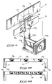
- a multi-head dot matrix printer 10 is shown in FIGURE 1.
- the multi-head dot matrix printer 10 has three print heads 12a, 12b, and 12c positioned at preset distances on a reciprocating print head carriage.
- the printing elements contained in the print heads 12a, 12b, and 12c face a platen 14.
- the recording medium such as paper
- the print heads 12a, 12b, and 12c traverse the paper in a reciprocating pattern in a direction perpendicular to the direction of travel of the paper.
- the conventional printer ribbon cartridge 16 has a cartridge housing 20 which houses and protects a continuous print ribbon 18.
- the cartridge housing 20 includes a housing body 21 and two guide arms 22 and 24.
- the housing body 21 stores the bulk of the print ribbon 18.
- the two guide arms 22 and 24 extend substantially perpendicular from the housing body 21 to support and guide the print ribbon 18 from the housing body 21 and around the printing elements of the print heads 12a, 12b, and 12c.
- the printer ribbon cartridge 16 also has multiple ribbon guides 26a, 26b, and 26c, which guide the print ribbon 18 between the respective printing elements of print heads 12a, 12b, and 12c and the platen 14.
- the ribbon guides 26a, 26b, and 26c are slidably mounted to the print ribbon 18 so that the ribbon guides 26a, 26b, and 26c may easily slide along the print ribbon 18 as the print heads 12a, 12b, and 12c are moved back and forth across the recording medium.
- a user To install the conventional multi-head printer ribbon cartridge 16, a user first mounts the housing 16 on the print head carriage. The exposed print section of the print ribbon 18 has some slack and thus lies loosely near the print heads 12a, 12b, and 12c. The user then separately mounts each of the ribbon guides 26a, 26b, and 26c onto respective printing heads 12a, 12b, and 12c. As illustrated in FIGURE 3, this step requires the user to grasp each ribbon guide 26a and slide the ribbon guide 26a onto the print head 12a. As a final step, the user tightens the print ribbon 18 to remove any excess slack and to ensure that the print ribbon 18 is properly positioned over the printing elements of the print heads 12a, 12b, and 12c.
- the conventional printer ribbon cartridge 16 has two major disadvantages. First, installation of the conventional printer ribbon cartridge is very cumbersome. Each of the ribbon guides 26a, 26b, and 26c slide and twist relative to, and independently of, the other ribbon guides. As a result, the user must individually mount each of the ribbon guides 26a, 26b, and 26c on the respective print heads 12a, 12b, and 12c. Second, installation is very messy. Because the user must handle each of the ribbon guides 26a, 26b, and 26c individually, the user's fingers are in close proximity with the print ribbon 18 as shown in FIGURE 3. As a result, the user normally cannot avoid handling the messy and ink soaked print ribbon 18.
- the present invention overcomes the cited disadvantages of the conventional printer ribbon cartridges.
- the present invention facilitates easy installation. The user may simultaneously mount all of the ribbon guides onto the respective print heads.
- the present invention reduces the installation mess because the user handles only the ribbon guide carrier, rather than each individual ribbon guide.
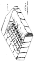
- FIGURE 4 shows a multi-head computer printer ribbon cartridge 50 according to the present invention for use in a multi-head printer.
- the printer ribbon cartridge 50 has a cartridge housing 52 which houses and protects the print ribbon 54.
- the cartridge housing 52 includes a housing body 56 and two guide arms 58 and 60.
- the two guide arms 58 and 60 extend substantially perpendicular from the housing body 56 to support and guide the print ribbon 54 from the housing body 56 and around the print heads (not shown).
- the cartridge housing 52 contains the bulk of the print ribbon 54, but a small print section of the print ribbon 54 is exposed between the two guide arms 56 and 60.
- the exposed print section of the print ribbon 54 extends in from of the printing elements of the print heads.
- the printer ribbon cartridge 50 also includes three ribbon guides 62a, 62b, and 62c which are slidably coupled to the exposed print section of the print ribbon 54.
- the ribbon guides 62a, 62b, and 62c are mounted on the print heads of a printer, as will be discussed below in more detail.
- the number of ribbon guides 62a, 62b, and 62c employed on the printer ribbon cartridge 50 corresponds to the number of print heads of the multi-head printer. Accordingly, although three ribbon guides 62a, 62b, and 62c are shown in FIGURE 4, the present invention contemplates a printer ribbon cartridge having two, three, four, or more ribbon guides.
- the printer ribbon cartridge 50 further includes a releasable ribbon guide carrier 70 which is operatively connected to the ribbon guides 62a, 62b, and 62c.
- the ribbon guide carrier 70 supports the ribbon guides 62a, 62b, and 62c on the exposed print section of the print ribbon 54 at prescribed distances A and B.
- the distances A and B are approximately equal to the preset spaced distances among the print heads of the multi-head printer (for example, the spacing distances among the print heads 12a, 12b, and 12c of the dot matrix printer 10 in FIGURE 1).
- the distance A is preferably, but not necessarily, equal to the distance B.
- the ribbon guide carrier 70 is preferably formed of plastic, but may be formed of other materials, such as, for example, waxed cardboard.
- the ribbon guide carrier 70 has a body 72, three attachment regions arranged on the back of the body 72, and two sets of members 74a, 74b and 76a, 76b.
- the attachment regions are not depicted in the perspective view shown in FIGURE 4, but are shown in FIGURE 8A which depicts the back side of the ribbon guide carrier 70.
- the three attachment regions 78a, 78b, and 78c are rectangular areas positioned on the body 72 at prescribed distances to support the ribbon guides 62a, 62b, and 62c at the preset spaced distances of the print heads of the multi-head printer.
- the attachment regions 78a, 78b, and 78c may be formed of double-sided tape, glue, or any other adhesive material.
- the present invention contemplates other means for releasably supporting the ribbon guides 62a, 62b, and 62c, so long as the means adequately supports the ribbon guides 62a, 62b, and 62c while the guides are being mounted onto the print heads, and then permits the release of the ribbon guides 62a, 62b, and 62c from the ribbon guide carrier 70 once the ribbon guides are properly mounted.
- the ribbon guide carrier may be operatively connected to the ribbon guides via a mechanical, non-adhesive, design.
- the ribbon guide carrier and ribbon guides may be formed as an integral piece of plastic whereby the ribbon guides are attached to the ribbon guide carrier via detachable joints. After the ribbon guides are mounted onto the print heads, the ribbon guide carrier is detached therefrom by breaking the joints. Therefore, the present invention is not limited to the descriptive term "attachment regions", which is merely employed herein to describe the preferred embodiment.
- the ribbon guide carrier 70 shown in FIGURE 8A has three attachment regions 78a, 78b, and 78c.
- the number of regions may, of course, be one, two, three, four or more.
- a second embodiment of a ribbon guide carrier 80 may have one continuous attachment region 82 spread across the length of the body as shown in FIGURE 8B. In this second embodiment, all of the ribbon guides 62a, 62b, and 62c are supported by the single attachment region 82.
- FIGURE 9 illustrates how each ribbon guide is connected to the ribbon guide carrier.
- the attachment region 78a (shown in phantom) of the body 72 is inserted between a primary lip 63 (also shown in phantom) and a secondary lip 65 of the ribbon guide 62a.
- the attachment region 78a is releasably connected to the primary lip 63 via an adhesive bond.
- the ribbon guide carrier 70 supports and aligns the ribbon guides 62a, 62b, and 62c because the attachment regions 78a, 78b, and 78c on the body 72 are connected to the respective primary lips (not shown) on the ribbon guides 62a, 62b, and 62c.
- the preferred embodiment is described as having the attachment regions 78a, 78b and 78c on only one side of the body 72, the present invention contemplates placing attachment regions on both sides of the body 72.
- the body 72 of the ribbon guide carrier 70 is planar and extends in first direction from a first end to a second end.
- the two sets of members 74a, 74b and 76a, 76b extend in a second direction, which is substantially perpendicular to the first direction, from the opposing ends of the body 72.
- Members 74a and 74b are adjacently aligned and define a slot 75 which has sufficient dimensions to permit passage of the print ribbon 54 (as shown in FIGURE 4).
- members 76a and 76b are adjacently aligned and define a slot 77 which has sufficient dimensions to permit passage of the print ribbon 54.
- the two sets of members 74a, 74b and 76a, 76b assist in keeping the print ribbon 54 taught to facilitate installation.
- the ribbon guide carrier 70 has been described as having two members on each end of the body 72; but, three or more members may be employed on each end of the body 72, whereby the print ribbon 54 is woven through the multiple members.
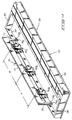
- the installation of the printer ribbon cartridge 50 according to the present invention will now be described with reference to FIGURES 5-7 and 9.
- the installation is described with reference to a dot matrix printer 100 having three print heads 102a, 102b, and 102c positioned at preset spaced distances on a reciprocating print head carriage.
- the cartridge housing 52 is first mounted on the print head carriage as shown in FIGURE 5. At this time, the exposed print section of the print ribbon 54 has some slack, thereby allowing the user to lift the ribbon guide carrier 70 (and thus, the three ribbon guides 62a, 62b, and 62c) above the print heads 102a, 102b, and 102c. Notice that the ribbon guides 62a, 62b, and 62c are connected to the ribbon guide carrier 70 at prescribed spaced distances corresponding to the preset spaced distances of the print heads 102a, 102b, and 102c. The ribbon guide carrier 70 maintains the ribbon guides 62a, 62b, and 62c in a single plane to maintain the ribbon guides in alignment. The ribbon guide carrier 70 serves as a handle and mounting fixture to mount the three ribbon guides 62a, 62b, and 62c in a single downward stroke.
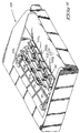
- FIGURE 6 the user then mounts the three ribbon guides 62a, 62b, and 62c onto respective print heads 102a, 102b, and 102c.
- FIGURE 9 illustrates the mounting of one ribbon guide onto one print head in more detail.
- the ribbon guide 62a has two collars 63a and 63b which are directed onto two alignment pins 103a and 103b of the print head 102a.
- the pins 103a and 103b slide through the collars 63a and 63b and fasten into a slot provided on the ribbon guide 62a.
- the ribbon guide 62a guides the print ribbon 54 over the printing elements of the print head 102a.
- the ribbon guides 62a, 62b, and 62c are horizontally aligned on the ribbon guide carrier 70 such that the ribbon guides 62a, 62b, and 62c are simultaneously mounted onto respective print heads 102a, 102b, and 102c.
- the ribbon guides 62a, 62b, and 62c may be staggered vertically, with respect to one another, on the ribbon guide carrier 70 such that the ribbon guides 62a, 62b, and 62c are sequentially mounted onto the print heads 102a, 102b, and 102c.
- the collars of ribbon guide 62a are first slid onto the pegs of the print head 102a, then the collars of the ribbon guide 62b are slid onto the pegs of the print head 102b, and finally the collars of the ribbon guide 62c are slid onto the pegs of the print head 102c.
- Vertically staggering the ribbon guides 62a, 62b, and 62c may help facilitate installation.
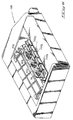
- the user releases the ribbon guides 62a, 62b, and 62c from the ribbon guide carrier 70, and removes the ribbon guide carrier 70, as shown in FIGURE 7.
- the user tightens the print ribbon 54 to take up any undesired slack.
- the preferred embodiment of the present invention has been described as employing a releasable ribbon guide carrier.
- the ribbon guide carrier may remain attached to the ribbon guides, and not removed after the guides are mounted on the print heads.
- the ribbon guide carrier may be permanently attached to the ribbon guides in such a manner which permits the ribbon guide to be moved to a non-interfering position after installation.
- the present invention has at least two significant advantages.
- First, the present invention facilitates easy installation because the user may simultaneously mount all three ribbon guides onto the respective print heads.
- the ribbon guide carrier prevents the ribbon guides from independently twisting around, and sliding along, the exposed print section of the print ribbon during storage and handling.
- the ribbon guide carrier guides the ribbon guides onto the print heads in an efficient and effective manner.
Landscapes
- Impression-Transfer Materials And Handling Thereof (AREA)
- Packaging Of Annular Or Rod-Shaped Articles, Wearing Apparel, Cassettes, Or The Like (AREA)
- Artificial Filaments (AREA)
- Photographic Developing Apparatuses (AREA)
- Ultra Sonic Daignosis Equipment (AREA)
Applications Claiming Priority (2)
| Application Number | Priority Date | Filing Date | Title |
|---|---|---|---|
| US07/718,629 US5129745A (en) | 1991-06-21 | 1991-06-21 | Computer printer ribbon cartridge for multi-head printers |
| US718629 | 1991-06-21 |
Publications (3)
| Publication Number | Publication Date |
|---|---|
| EP0519331A2 true EP0519331A2 (de) | 1992-12-23 |
| EP0519331A3 EP0519331A3 (en) | 1993-03-24 |
| EP0519331B1 EP0519331B1 (de) | 1996-10-16 |
Family
ID=24886844
Family Applications (2)
| Application Number | Title | Priority Date | Filing Date |
|---|---|---|---|
| EP92109844A Expired - Lifetime EP0519331B1 (de) | 1991-06-21 | 1992-06-11 | Bandkassette für Drucker |
| EP19920110489 Withdrawn EP0519517A3 (en) | 1991-06-21 | 1992-06-22 | Printer ribbon cartridge |
Family Applications After (1)
| Application Number | Title | Priority Date | Filing Date |
|---|---|---|---|
| EP19920110489 Withdrawn EP0519517A3 (en) | 1991-06-21 | 1992-06-22 | Printer ribbon cartridge |
Country Status (4)
| Country | Link |
|---|---|
| US (1) | US5129745A (de) |
| EP (2) | EP0519331B1 (de) |
| AT (1) | ATE144202T1 (de) |
| DE (1) | DE69214525D1 (de) |
Family Cites Families (21)
| Publication number | Priority date | Publication date | Assignee | Title |
|---|---|---|---|---|
| US1323894A (en) * | 1919-12-02 | Actuating mechanism for calculating-machines | ||
| US835722A (en) * | 1906-03-26 | 1906-11-13 | Underwood Typewriter Co | Type-writer-ribbon threader. |
| US1591243A (en) * | 1924-04-08 | 1926-07-06 | Smith Benjamin Shaw | Adding-machine-ribbon attachment |
| US2518893A (en) * | 1946-07-13 | 1950-08-15 | Charles P Huether | Detachable ribbon guide for typewriting machines |
| US2788111A (en) * | 1956-02-21 | 1957-04-09 | Yetta B Spiegel | Typewriter ribbon sheath |
| US2895586A (en) * | 1957-05-24 | 1959-07-21 | Luco Eugene Di | Ribbon inserter |
| US3047121A (en) * | 1958-01-17 | 1962-07-31 | Sperry Rand Corp | Typewriter ribbon guard and mounting |
| DE1976232U (de) * | 1967-10-19 | 1968-01-04 | Klaus Gerhardt | Farbband fuer schreib-, rechen-, buchungsmaschinen od. dgl. |
| US4284364A (en) * | 1979-02-21 | 1981-08-18 | Exxon Research & Engineering Co. | Ribbon tensioning for a cartridge with flexible guides |
| US4285604A (en) * | 1979-10-19 | 1981-08-25 | International Business Machines Corporation | Ribbon shield for printer |
| US4403874A (en) * | 1980-03-25 | 1983-09-13 | Ramtek Corporation | Color printer and multi-ribbon cartridge therefor |
| US4504160A (en) * | 1980-03-25 | 1985-03-12 | Ramtek Corporation | Color printer and multi-ribbon cartridge therefor |
| US4483633A (en) * | 1983-02-18 | 1984-11-20 | Bell & Howell Company | Matrix print head printer |
| US4576490A (en) * | 1983-12-14 | 1986-03-18 | Oki Electric Industry Co., Ltd. | Multihead serial printer |
| IT1176062B (it) * | 1984-04-16 | 1987-08-12 | Honywell Information Systems I | Cartuccia a nastro inchiostrato multicolare e relativo meccanismo di posizionamento in una stampante seriale ad impatto |
| JPS60224572A (ja) * | 1984-04-20 | 1985-11-08 | Canon Inc | 転写記録装置 |
| JPH0312533Y2 (de) * | 1984-11-02 | 1991-03-25 | ||
| JPS61188176A (ja) * | 1985-02-18 | 1986-08-21 | Fujitsu Ltd | 熱転写プリンタの印字方式 |
| JPS61248776A (ja) * | 1985-04-26 | 1986-11-06 | Konishiroku Photo Ind Co Ltd | インクリボンカセツト及びこれを用いるプリンタ |
| JPS61252184A (ja) * | 1985-05-02 | 1986-11-10 | Alps Electric Co Ltd | 熱転写プリンタ |
| US4806948A (en) * | 1987-02-17 | 1989-02-21 | Ncr Corporation | Ribbon separating mechanism for thermal printer |
-
1991
- 1991-06-21 US US07/718,629 patent/US5129745A/en not_active Expired - Fee Related
-
1992
- 1992-06-11 EP EP92109844A patent/EP0519331B1/de not_active Expired - Lifetime
- 1992-06-11 AT AT92109844T patent/ATE144202T1/de not_active IP Right Cessation
- 1992-06-11 DE DE69214525T patent/DE69214525D1/de not_active Expired - Lifetime
- 1992-06-22 EP EP19920110489 patent/EP0519517A3/en not_active Withdrawn
Also Published As
| Publication number | Publication date |
|---|---|
| EP0519517A3 (en) | 1993-03-24 |
| ATE144202T1 (de) | 1996-11-15 |
| US5129745A (en) | 1992-07-14 |
| DE69214525D1 (de) | 1996-11-21 |
| EP0519331B1 (de) | 1996-10-16 |
| EP0519517A2 (de) | 1992-12-23 |
| EP0519331A3 (en) | 1993-03-24 |
Similar Documents
| Publication | Publication Date | Title |
|---|---|---|
| US6277456B1 (en) | Labeling media and method of making | |
| US4673304A (en) | Thermal printer ribbon cartridge for wide ribbons | |
| DE3174728D1 (en) | Print head for an ink-jet printer with a reciprocating print head carrier | |
| US4568108A (en) | Continuous forms leader | |
| EP2974870A2 (de) | Streifendrucker zur herstellung eines selbstlaminierenden bedruckten etiketts, bandkassette und farbband dafür | |
| EP0519331B1 (de) | Bandkassette für Drucker | |
| DE69413935D1 (de) | Übertragungsbandkassette für einen Wärmeübertragungsdrucker | |
| ATE161483T1 (de) | Kassettensystem für wärmeübertragungsfarbbänder | |
| US8205984B2 (en) | Web printer and support structure | |
| US5599120A (en) | Adapter for ink jet printing onto adhesive binding tape | |
| GB2199307B (en) | A printer provided with an ink ribbon cassette | |
| US2226863A (en) | Typewriter ribbon device | |
| DE3561141D1 (en) | Label printer | |
| EP0519497A2 (de) | Farbbandführungsanlage für Drucker | |
| FR2708526B1 (fr) | Support de ruban encreur pour imprimante à impression par transfert thermique. | |
| JPS58212977A (ja) | サ−マルプリンタ | |
| JPS63230460A (ja) | ウエブ巻取方法および装置 | |
| JPH1069223A (ja) | 印刷用材 | |
| JPS591270A (ja) | 印字装置 | |
| JPH0367876B2 (de) | ||
| JPS627495Y2 (de) | ||
| JPH0242456Y2 (de) | ||
| JP2562596B2 (ja) | ウエブ巻取方法および装置 | |
| JPS597080A (ja) | ドツトプリンタ | |
| JPH0623760U (ja) | リボンカセットおよびこれを用いたプリンタ |
Legal Events
| Date | Code | Title | Description |
|---|---|---|---|
| PUAI | Public reference made under article 153(3) epc to a published international application that has entered the european phase |
Free format text: ORIGINAL CODE: 0009012 |
|
| AK | Designated contracting states |
Kind code of ref document: A2 Designated state(s): AT BE CH DE DK ES FR GB GR IT LI LU MC NL PT SE |
|
| PUAL | Search report despatched |
Free format text: ORIGINAL CODE: 0009013 |
|
| AK | Designated contracting states |
Kind code of ref document: A3 Designated state(s): AT BE CH DE DK ES FR GB GR IT LI LU MC NL PT SE |
|
| 17P | Request for examination filed |
Effective date: 19930923 |
|
| 17Q | First examination report despatched |
Effective date: 19950511 |
|
| GRAH | Despatch of communication of intention to grant a patent |
Free format text: ORIGINAL CODE: EPIDOS IGRA |
|
| GRAA | (expected) grant |
Free format text: ORIGINAL CODE: 0009210 |
|
| AK | Designated contracting states |
Kind code of ref document: B1 Designated state(s): AT BE CH DE DK ES FR GB GR IT LI LU MC NL PT SE |
|
| PG25 | Lapsed in a contracting state [announced via postgrant information from national office to epo] |
Ref country code: IT Free format text: LAPSE BECAUSE OF FAILURE TO SUBMIT A TRANSLATION OF THE DESCRIPTION OR TO PAY THE FEE WITHIN THE PRE;WARNING: LAPSES OF ITALIAN PATENTS WITH EFFECTIVE DATE BEFORE 2007 MAY HAVE OCCURRED AT ANY TIME BEFORE 2007. THE CORRECT EFFECTIVE DATE MAY BE DIFFERENT FROM THE ONE RECORDED.SCRIBED TIME-LIMIT Effective date: 19961016 Ref country code: FR Effective date: 19961016 Ref country code: CH Effective date: 19961016 Ref country code: NL Free format text: LAPSE BECAUSE OF FAILURE TO SUBMIT A TRANSLATION OF THE DESCRIPTION OR TO PAY THE FEE WITHIN THE PRESCRIBED TIME-LIMIT Effective date: 19961016 Ref country code: AT Effective date: 19961016 Ref country code: BE Effective date: 19961016 Ref country code: GR Free format text: LAPSE BECAUSE OF FAILURE TO SUBMIT A TRANSLATION OF THE DESCRIPTION OR TO PAY THE FEE WITHIN THE PRESCRIBED TIME-LIMIT Effective date: 19961016 Ref country code: ES Free format text: THE PATENT HAS BEEN ANNULLED BY A DECISION OF A NATIONAL AUTHORITY Effective date: 19961016 Ref country code: DK Effective date: 19961016 Ref country code: LI Effective date: 19961016 |
|
| REF | Corresponds to: |
Ref document number: 144202 Country of ref document: AT Date of ref document: 19961115 Kind code of ref document: T |
|
| REF | Corresponds to: |
Ref document number: 69214525 Country of ref document: DE Date of ref document: 19961121 |
|
| PG25 | Lapsed in a contracting state [announced via postgrant information from national office to epo] |
Ref country code: SE Effective date: 19970116 Ref country code: PT Effective date: 19970116 |
|
| PG25 | Lapsed in a contracting state [announced via postgrant information from national office to epo] |
Ref country code: DE Effective date: 19970117 |
|
| NLV1 | Nl: lapsed or annulled due to failure to fulfill the requirements of art. 29p and 29m of the patents act | ||
| EN | Fr: translation not filed | ||
| EN | Fr: translation not filed |
Free format text: CORRECTIONS |
|
| REG | Reference to a national code |
Ref country code: CH Ref legal event code: PL |
|
| PG25 | Lapsed in a contracting state [announced via postgrant information from national office to epo] |
Ref country code: GB Free format text: LAPSE BECAUSE OF NON-PAYMENT OF DUE FEES Effective date: 19970611 |
|
| PG25 | Lapsed in a contracting state [announced via postgrant information from national office to epo] |
Ref country code: LU Free format text: LAPSE BECAUSE OF NON-PAYMENT OF DUE FEES Effective date: 19970630 |
|
| PLBE | No opposition filed within time limit |
Free format text: ORIGINAL CODE: 0009261 |
|
| STAA | Information on the status of an ep patent application or granted ep patent |
Free format text: STATUS: NO OPPOSITION FILED WITHIN TIME LIMIT |
|
| 26N | No opposition filed | ||
| PG25 | Lapsed in a contracting state [announced via postgrant information from national office to epo] |
Ref country code: MC Effective date: 19971231 |
|
| GBPC | Gb: european patent ceased through non-payment of renewal fee |
Effective date: 19970611 |