EP0519318B1 - Apparatus and transport unit for removing injection moulded articles from a plastic injection moulding machine - Google Patents
Apparatus and transport unit for removing injection moulded articles from a plastic injection moulding machine Download PDFInfo
- Publication number
- EP0519318B1 EP0519318B1 EP92109806A EP92109806A EP0519318B1 EP 0519318 B1 EP0519318 B1 EP 0519318B1 EP 92109806 A EP92109806 A EP 92109806A EP 92109806 A EP92109806 A EP 92109806A EP 0519318 B1 EP0519318 B1 EP 0519318B1
- Authority
- EP
- European Patent Office
- Prior art keywords
- pallet
- transport
- pallets
- transport unit
- tower
- Prior art date
- Legal status (The legal status is an assumption and is not a legal conclusion. Google has not performed a legal analysis and makes no representation as to the accuracy of the status listed.)
- Expired - Lifetime
Links
Images


Classifications
-
- B—PERFORMING OPERATIONS; TRANSPORTING
- B29—WORKING OF PLASTICS; WORKING OF SUBSTANCES IN A PLASTIC STATE IN GENERAL
- B29C—SHAPING OR JOINING OF PLASTICS; SHAPING OF MATERIAL IN A PLASTIC STATE, NOT OTHERWISE PROVIDED FOR; AFTER-TREATMENT OF THE SHAPED PRODUCTS, e.g. REPAIRING
- B29C45/00—Injection moulding, i.e. forcing the required volume of moulding material through a nozzle into a closed mould; Apparatus therefor
- B29C45/17—Component parts, details or accessories; Auxiliary operations
- B29C45/1769—Handling of moulded articles or runners, e.g. sorting, stacking, grinding of runners
-
- B—PERFORMING OPERATIONS; TRANSPORTING
- B29—WORKING OF PLASTICS; WORKING OF SUBSTANCES IN A PLASTIC STATE IN GENERAL
- B29C—SHAPING OR JOINING OF PLASTICS; SHAPING OF MATERIAL IN A PLASTIC STATE, NOT OTHERWISE PROVIDED FOR; AFTER-TREATMENT OF THE SHAPED PRODUCTS, e.g. REPAIRING
- B29C31/00—Handling, e.g. feeding of the material to be shaped, storage of plastics material before moulding; Automation, i.e. automated handling lines in plastics processing plants, e.g. using manipulators or robots
-
- Y—GENERAL TAGGING OF NEW TECHNOLOGICAL DEVELOPMENTS; GENERAL TAGGING OF CROSS-SECTIONAL TECHNOLOGIES SPANNING OVER SEVERAL SECTIONS OF THE IPC; TECHNICAL SUBJECTS COVERED BY FORMER USPC CROSS-REFERENCE ART COLLECTIONS [XRACs] AND DIGESTS
- Y10—TECHNICAL SUBJECTS COVERED BY FORMER USPC
- Y10S—TECHNICAL SUBJECTS COVERED BY FORMER USPC CROSS-REFERENCE ART COLLECTIONS [XRACs] AND DIGESTS
- Y10S425/00—Plastic article or earthenware shaping or treating: apparatus
- Y10S425/117—Pallet
-
- Y—GENERAL TAGGING OF NEW TECHNOLOGICAL DEVELOPMENTS; GENERAL TAGGING OF CROSS-SECTIONAL TECHNOLOGIES SPANNING OVER SEVERAL SECTIONS OF THE IPC; TECHNICAL SUBJECTS COVERED BY FORMER USPC CROSS-REFERENCE ART COLLECTIONS [XRACs] AND DIGESTS
- Y10—TECHNICAL SUBJECTS COVERED BY FORMER USPC
- Y10S—TECHNICAL SUBJECTS COVERED BY FORMER USPC CROSS-REFERENCE ART COLLECTIONS [XRACs] AND DIGESTS
- Y10S425/00—Plastic article or earthenware shaping or treating: apparatus
- Y10S425/118—Pallet feeder
Definitions
- the invention relates to a device according to the preamble of claim 1 and a transport unit according to the preamble of claim 7.
- the molded parts coming from the injection mold are filled into pallets which are located in a filling station. These pallets are provided in a pallet tower in transport units, with the empty pallets being removed from one transport unit and the filled pallet being picked up in another transport unit.
- the transport units consist of a transport pallet on which several stackable pallets are connected to form a stacking unit. Filled transport units are transferred from a transfer device to a transport vehicle which can be moved linearly parallel to the vertical plane of symmetry of the injection molding machine and which is also set up for the transport of injection molds to be replaced in such a way that a molded part container and an injection mold can be transported at the same time.
- the pallets can be removed individually from the transport unit and fed back to them after filling. No vertical movements of the elevator are required to change the pallet. However, while the pallet is being filled, the elevator is still freely movable vertically, so that the transport units are fed with empty pallets as well as the removal of a transport unit with filled pallets at any level. In addition, even with the most unfavorable replacement of the transport unit in the pallet tower, the downtime is reduced in that it is possible in principle to remove any empty pallet, regardless of whether it is arranged in the transport unit above, below or in the middle. Nevertheless, the pallets cannot easily use the space in the transport unit, since the guides for the individual pallets are firmly connected to the transport unit. In this respect, larger parts can only be transported in that individual pallet guides are not occupied, which both increases the mass to be moved and reduces the transport capacity of the individual transport unit due to the intervention of the pallet guides in the available space.
- JP-OS 57-184001 Patent Abstracts of Japan, Volume 7, No. 29 (M-191) (1174)
- JP-OS 60-262776 Patent Abstracts of Japan, Volume 10, No. 142 (M-481) (2199)
- Transport trolleys are known in which individual molded part containers are supported on support plates or workpieces are individually accommodated so that they can be removed for further processing by a horizontal movement.
- the supports for the molded parts or the workpieces are fixed at constant intervals, so that an optimal use of space in the available transport space depending on the size of the molded parts or workpieces is difficult.
- the molded part containers are pulled out of the transport carriage by means of a hydraulic device and then continuously filled with the molded parts brought about.
- the molded part container is gradually pushed back into the transport carriage under the injected molded parts, so that the transport carriage cannot be moved freely during filling.
- the supply of the molded parts is interrupted by a flap until the dolly moves vertically, a new pallet has been removed and this has been transferred to the starting position.
- the object of the invention is to further develop a device and a transport unit of the type mentioned at the outset in such a way that they can easily be adapted to different pallet sizes without increasing the expenditure on programming.
- the space under the transport units is used for an immediate transfer to the transport vehicle.
- the programming effort is further reduced. If necessary, sensors are used which, on the one hand, recognize how many pallets are provided per transport unit and, on the other hand, also recognize when the pallet is introduced into the filling station whether the present pallet is even suitable for the injection parts coming out of the injection molding machine. This further reduces the susceptibility to faults.
- the transport units can be transported with the same transport vehicle as the injection molds when changing the injection mold or as the plasticizing cylinder. From the point of view of the transport vehicle, the transfer to the transport vehicle can take place both actively and passively in that, for example, the transport vehicle removes the filled transport units directly under the pallet tower.
- the transport pallet can be provided according to a modular principle both for receiving only a large pallet and for receiving several pallets. When picking up a large pallet, the vertical support elements of the transport pallet are simply removed if necessary.
- support plates are provided which are guided on the guide rails of the transport unit in an embodiment according to claim 9.
- the transport units can be transported with the same transport vehicle as the injection molds when changing the injection mold or as the plasticizing cylinder.
- the plastic injection molding machine on which the device is implemented comprises a horizontal injection molding unit S and a horizontally arranged mold clamping unit W. Both units are supported on a machine frame 10.
- the removal of the injection parts 63 resulting from the injection molding operation from the injection molding machine takes place with the aid of pallets 55.
- These are filled in a filling station Fs in the area of the injection molding machine.
- the filling station is optionally arranged inside the injection molding machine (FIGS. 1-3) or outside the same in the region of the end face delimiting the mold clamping unit (FIGS. 4, 5).
- the pallet 55 is filled with the aid of a removal device H which removes the injection parts 63 from the open injection mold.
- the molded parts are placed in rows with fixation in depressions 55g (FIGS. 13-15) as a result of gradual movements of the gripper of the removal device H transversely to the plane of symmetry ss.
- the pallet 55 is filled by means of a conveyor belt 18, which transports the molded parts parallel to the plane of symmetry ss.
- the conveyor belt 18 is in turn fed by the gripper of the removal device.
- the pallets 55 are designed such that they can be stacked to form stacking units, if necessary, with mutual centering. In order to be ready for filling in the filling station Fs, however, they are individually supported in a pallet tower 54.
- the pallet tower 54 is arranged between the filling station Fs and another means of transport, for example a transport vehicle F (FIG. 2) or a roller conveyor, and is located on the rear of the injection molding machine outside of its plan area. It is parked on the floor and towers above the injection molding machine.
- An elevator 53 can be moved on vertical skeleton elements 54a ′ of the profile skeleton 54a of the pallet tower 54 by means of rollers 53d.
- the elevator 53 is prepared for accommodating at least two transport units T, T '.
- the elevator which is otherwise freely movable during the filling process, is located when the pallet 55 is removed and when the filled pallet 55 is transferred to the pallet tower 54 in a position which at least transfers the filled pallet to the place in the respective transport unit T, T 'allows the pallet 55 has previously been removed from this transport unit.
- the transfer of the pallets 55 to be filled into the filling station Fs is done only by a horizontal movement. Before this movement is initiated, the elevator is in a position, following a vertical movement monitored by a displacement measuring device 52, in which pallet guides 59 of the respective transport unit connect to pallet guides 58 of the filling station Fs. After filling, the pallets 55 are connected to the transport pallet again to form a transport unit which can then be handed over to the transport vehicle or taken over by it.
- the drive device 57 which enables the horizontal movement of the pallets without requiring any further movement of the elevator, comprises an endless chain 57b arranged below the pallet 55 located in the filling station.
- a driver pin 57a of this chain is coupled in the course of a semicircular movement on the chain wheel 57c with a support plate via a transverse groove 51a 'of the coupling element 51a.
- This support plate 51 slides on the pallet guides 59 of the transport unit and carries the respective pallets in a recess 51b, so that any pallets can be assigned to the respective support plates.
- the pallets themselves can also be guided on the pallet guides 58, 59, but this contributes considerably to wear on the pallets, which can be avoided by interposing support plates. As can be seen from FIGS.
- the axes of the endless chain 57b in the form of a link chain of the drive device 57 are arranged vertically.
- the driver pin as can be seen in particular from FIG. 2a, is fastened to the chain links in such a way that it describes a larger radius than the chain wheel and projects above the chain.
- the coupling itself takes place in that the follower pin 57a is inserted into the transverse groove, which in the present case is only half milled out of full material, as a result of lateral control.
- switching elements 57e are also provided on the chain, which terminate the movement of the chain when the limit switches 57f are approached (FIG. 2.2a).
- the profile skeleton 54a of the pallet tower 54 consists of two skeleton elements 54a 'which are approximately in a vertical plane and are connected to one another by horizontal skeleton elements.
- the pallet tower is connected to the injection molding machine by a plurality of support elements 50.
- This primarily flat arrangement of the profile skeleton allows both the rear and side connection of the injection molding machine to a transport vehicle F.
- This connection option is continued as the lifting spindle device, which is provided for the mobility of the elevator, also basically in the vertical projection of the profile skeleton 54a is arranged.
- a threaded nut 62b attached to the elevator 53 is in engagement with the rotating threaded spindle 62a of the lifting spindle device, which spindle is articulated at the top and bottom of the profile skeleton.
- the motor 62c of the lifting spindle device is also arranged almost horizontally in the vertical projection of the profile skeleton 54a and drives the lifting spindle 62a via a deflection gear.
- the pallet tower 54 is at least twice as high as the elevator 53, in which at least two transport units T, T 'can be accommodated one above the other.
- the elevator itself has two receiving forks 53a for the transport units, which receiving forks are formed by two parallel rails 53a 'which are connected to one another via at least one transverse web 53a''.
- the transport unit is to be understood as the unit of transport pallet 56 with a different number of pallets 55, which, however, always have the same outer dimensions if possible.
- signal transmitters 60 are arranged on the profile skeleton 54a, the number of which is the largest possible Number of pallets in the transport unit T, T 'and their mutual distance corresponds to a pallet 55 of the lowest height.
- there is a bar code 55k on the pallets 55 so that the type of the pallet can be scanned by a reading sensor 61 arranged at the filling station Fs and it can thus be ensured that the receiving troughs 55g of the pallets also match the molded parts 63.
- the transport pallet itself consists of two guide rails 56b which are connected to one another by a cross piece 56c (in the specific exemplary embodiment a cross plate).
- This basic element already has a support profile which corresponds to the support profile of the injection mold 14a, 14b.
- the cross-sectional profile of the guide rails also corresponds to the cross-sectional profile of the contact plates 14a ', 14b' of the injection mold to be transported on the transport vehicle when changing the mold.
- a transport vehicle F (indicated only schematically in the drawing in FIG. 2) is already known from DE 36 17 094. This transport vehicle is intended to transport injection molds or transport units and thus opens up significant rationalization options for the transport system of the injection molding machine.
- a takeover device for the transport vehicle can actively remove the transport unit from the pallet tower or insert it into the rear or the side thereof.
- Another embodiment is of course also conceivable, in which the transport vehicle itself passively takes over the corresponding transport units.
- transverse grooves 56a are therefore already arranged on the guide rails 56b, into which a driver of a transport chain of the transport vehicle F can be steered.
- the basic element made of sheet metal by folding and punching, consisting of coherent guide rails and cross plate, is already prepared for modular upgrading.
- connecting elements 56d are therefore provided, if necessary vertical support elements 56e can be connected.
- the number of pallet guides 59 required depending on the pallet height can then be attached at any height of these support elements 56e, which allows great flexibility with regard to the pallet sizes.
- both the pallet guides 59 and the pallet guides 58 have angled end regions 59b, which allow easy transfer from the pallet tower to the filling station and vice versa.
- the bottom 55a which has the depressions 55g, is enclosed by a vertical protective wall 55f.
- the base area of the bottom 55a is, as shown in FIGS. 11-15 recognizable, smaller than the floor plan of the protective wall. This ensures a basic stackability of the pallets.
- the pallets With the centering area 55d, the pallets rest on the support plates 51.
- recesses 51b are provided in the support plates 51, which correspond to the respective centering area. Nevertheless, the pallets 55 can be stacked in a space-saving manner outside the pallet tower and the transport unit. The pallet is therefore not itself supported directly on the transport pallet 56, but indirectly via the support plate 51, the contour 51b 'of the recess 51b of the support plate corresponding to the upper edge 55m of a pallet 55.
- coding lugs 51c which are recognized by the signal generators 60, can be provided on the support plate 51 to identify the pallets or to identify the pallet height located in a transport unit. To this end the slide rail 51e is also slightly set back in its edge regions.
- the filling station arranged within the layout of the injection molding machine in the variant according to FIGS. 1-3 can be easily converted into the variant according to FIGS. 4,5 are converted, in which the filling station is outside the outline of the injection molding machine.
- the filling station lies in front of that end face of the injection molding machine that is adjacent to the mold clamping unit W.
- the assembly effort is essentially limited to the fact that instead of the pallet guide 58, an endless conveyor belt 18 is inserted into the injection molding machine at the same height level, so that the injection parts 63 can be placed directly on the conveyor belt.
- the pallet guide 58 is located approximately in the same horizontal plane e-e (FIG. 3) as the conveying surface of the conveyor belt, the height of this plane being approximately the height of the upper edge of the injection mold 14a, 14b.
- the pallets are individually supported in the transport unit, the pallets can be pulled out of the respective transport unit without any problems, the comparison being obvious with drawers which are pulled out of a cabinet. Because, like in a cabinet, the drawers can be pushed out and in individually independently of one another and in any order, the possibility also arises here of processing the pallets in any order, preferably being worked from top to bottom or from bottom to top.
- the filling is such that a pallet is first pulled out of the transport unit T, T ', then filled in the filling station Fs and then returned to the same place in the transport unit.
- the elevator is then lowered or raised until the next pallet is in the ready position.
- the entire elevator can move freely vertically, since there are no disruptive connecting elements or even Pallet parts remain in the movement space required for vertical movement.
- a filled transport unit can be easily removed and an empty transport unit can be transferred while a pallet is being filled.
- This vertical possibility of movement does not matter whether the transport vehicle itself is prepared for this, for example by means of a lifting device, to take over the transport units at any height. Rather, the transport vehicle F does not have to have any lifting device at all, since the elevator has enough time to transfer the filled transport unit to a transfer level for the transport vehicle.
Abstract
Description
Die Erfindung betrifft eine Vorrichtung entsprechend dem Oberbegriff des Patentanspruches 1 sowie eine Transporteinheit entsprechend dem Oberbegriff des Patentanspruches 7.The invention relates to a device according to the preamble of claim 1 and a transport unit according to the preamble of claim 7.
Bei einer bekannten Vorrichtung dieser Art (DE-PS 38 30 958) werden die aus dem Spritzwerkzeug kommenden Spritzteile in Paletten abgefüllt, die sich in einer Füllstation befinden. Diese Paletten werden in einem Palettenturm in Transporteinheiten bereitgestellt, wobei die Entnahme der leeren Paletten aus einer Transporteinheit erfolgt und die Aufnahme der gefüllten Palette in einer anderen Transporteinheit erfolgt. Die Transporteinheiten bestehen aus einer Transportpalette, auf der mehrere stapelbare Paletten zu einer Stapeleinheit verbunden sind. Gefüllte Transporteinheiten werden von einer Übergabeeinrichtung auf ein parallel zur vertikalen Symmetrieebene der Spritzgießmaschine linear verfahrbares Transportfahrzeug übergeben, das auch für den Transport auszuwechselnder Spritzwerkzeuge derart eingerichtet ist, daß gleichzeitig ein Spritzteilebehälter und ein Spritzwerkzeug transportiert werden können. Zur Entnahme der Paletten aus und zur Überführung der gefüllten Paletten in den Palettenturm ist jedoch ein großer programmtechnischer und konstruktiver Aufwand erforderlich, da die in die Füllstation einzuführenden Paletten erst durch mehrere Vertikal bewegungen des Fahrstuhls vereinzelt werden müssen. Dadurch können unerwünschte zeitliche Engpässe beim Austausch der Paletten entstehen.In a known device of this type (DE-PS 38 30 958), the molded parts coming from the injection mold are filled into pallets which are located in a filling station. These pallets are provided in a pallet tower in transport units, with the empty pallets being removed from one transport unit and the filled pallet being picked up in another transport unit. The transport units consist of a transport pallet on which several stackable pallets are connected to form a stacking unit. Filled transport units are transferred from a transfer device to a transport vehicle which can be moved linearly parallel to the vertical plane of symmetry of the injection molding machine and which is also set up for the transport of injection molds to be replaced in such a way that a molded part container and an injection mold can be transported at the same time. To remove the pallets from and for transferring the filled pallets into the pallet tower, however, a great amount of programming and design effort is required, since the pallets to be introduced into the filling station only have to be separated by several vertical movements of the elevator. This can lead to undesirable bottlenecks when exchanging the pallets.
Bei einer weiteren Vorrichtung nach der US-A 5,032,053 können die Paletten einzeln aus der Transporteinheit entnommen und dieser nach Befüllung wieder zugeführt werden. Zum Palettenwechsel sind keine Vertikalbewegungen des Fahrstuhls mehr erforderlich. Während der Befüllung der Palette ist der Fahrstuhl aber dennoch vertikal frei beweglich, so daß die Zuführung von Transporteinheiten mit leeren Paletten als auch die Entnahme einer Transporteinheit mit gefüllten Paletten auf jedem Niveau möglich ist. Zudem wird selbst bei ungünstigster Einwechslung der Transporteinheit in den Palettenturm die Stillstandszeit dadurch vermindert, daß es prinzipiell möglich ist, jede beliebige leere Palette zu entnehmen, gleichgültig, ob sie in der Transporteinheit oben, unten oder in der Mitte angeordnet ist. Dennoch können die Paletten nicht problemlos den in der Transporteinheit befindlichen Raum ausnutzen, da die Führungen für die einzelnen Paletten fest mit der Transporteinheit verbunden sind. Insofern können größere Teile nur dadurch transportiert werden, daß einzelne Palettenführungen nicht belegt werden, was sowohl die zu bewegenden Massen erhöht als auch aufgrund des Eingriffes der Palettenführungen in den zur Verfügung stehenden Raum die Transportkapazität der einzelnen Transporteinheit verringert.In a further device according to US Pat. No. 5,032,053, the pallets can be removed individually from the transport unit and fed back to them after filling. No vertical movements of the elevator are required to change the pallet. However, while the pallet is being filled, the elevator is still freely movable vertically, so that the transport units are fed with empty pallets as well as the removal of a transport unit with filled pallets at any level. In addition, even with the most unfavorable replacement of the transport unit in the pallet tower, the downtime is reduced in that it is possible in principle to remove any empty pallet, regardless of whether it is arranged in the transport unit above, below or in the middle. Nevertheless, the pallets cannot easily use the space in the transport unit, since the guides for the individual pallets are firmly connected to the transport unit. In this respect, larger parts can only be transported in that individual pallet guides are not occupied, which both increases the mass to be moved and reduces the transport capacity of the individual transport unit due to the intervention of the pallet guides in the available space.
Ferner sind aus der JP-OS 57-184001 (Patent Abstracts of Japan, Band 7, Nr. 29 (M-191) (1174)) bzw. der JP-OS 60-262776 (Patent Abstracts of Japan, Band 10, Nr. 142 (M-481) (2199)) Transportwagen bekannt, in denen einzelne Spritzteilebehälter auf Stützplatten abgestützt sind bzw. Werkstücke einzeln so aufgenommen sind, daß sie zur weiteren Bearbeitung durch eine horizontale Bewegung entnommen werden können. In beiden Fällen befinden sich jedoch die Abstützungen für die Spritzteile bzw. die Werkstücke in unveränderlich festen Abständen, daß eine optimale Raumausnutzung des zur Verfügung stehenden Transportraums in Abhängigkeit von der Größe der Spritzteile bzw. Werkstücke erschwert ist.Furthermore, JP-OS 57-184001 (Patent Abstracts of Japan, Volume 7, No. 29 (M-191) (1174)) and JP-OS 60-262776 (Patent Abstracts of Japan,
Bei der JP-OS 57-184001 (Patent Abstracts of Japan, Band 7, Nr. 29 (M-191) (1174)) werden die Spritzteilebehälter über eine hydraulische Einrichtung aus dem Transportwagen herausgezogen und anschließend mit den herbeigeführten Spritzteilen kontinuierlich befüllt. Um diese kontinuierliche Befüllung zu verwirklichen, wird unter den nachgeschobenen Spritzteilen der Spritzteilebehälter allmählich wieder zurück in den Transportwagen geschoben, so daß während der Befüllung der Transportwagen einer freien Bewegung nicht zugänglich ist. Sobald der Behälter befüllt ist, wird durch eine Klappe die weitere Zufuhr der Spritzteile so lange unterbrochen, bis der Transportwagen vertikal verfahren, eine neue Palette entnommen und diese in Ausgangsstellung überführt worden ist. Eine solche Konstruktion führt zu unerwünschten Unterbrechungen, da einerseits ein kontinuierliches Befüllen der Paletten insbesondere bei Verwendung einer Entnahmeeinrichtung nicht möglich ist und andererseits während des Wechsels des Transportwagens eine längere Pause eintritt, bis der neue Transportwagen wieder in Bereitschaftstellung ist.In JP-OS 57-184001 (Patent Abstracts of Japan, Volume 7, No. 29 (M-191) (1174)), the molded part containers are pulled out of the transport carriage by means of a hydraulic device and then continuously filled with the molded parts brought about. In order to achieve this continuous filling, the molded part container is gradually pushed back into the transport carriage under the injected molded parts, so that the transport carriage cannot be moved freely during filling. As soon as the container is filled, the supply of the molded parts is interrupted by a flap until the dolly moves vertically, a new pallet has been removed and this has been transferred to the starting position. Such a construction leads to undesirable interruptions, since on the one hand a continuous filling of the pallets is not possible, especially when using a removal device, and on the other hand there is a longer pause during the change of the transport carriage until the new transport carriage is ready again.
Aus der US-PS 4,687,403, insbesondere Figuren 2-5, ist es weiterhin bekannt, durch einen großen konstruktiven Aufwand einzelne Paletten aus einem Palettenstapel durch mehrere vertikale Bewegungen eines Fahrstuhls zu entnehmen. Dabei wird der Palettenstapel in zwei Palettenstapel unterteilt, so daß aus dem einen Palettenstapel die leeren Paletten entnommen und nach Befüllung dem anderen Palettenstapel zugeführt werden können. Nach Abarbeitung eines ganzen Palettenstapels wird dieser aus der Einrichtung hinausgeschoben und zur Abholung bereitgestellt, ohne daß entsprechende Transportpaletten vorhanden sind.From US Pat. No. 4,687,403, in particular FIGS. 2-5, it is also known to remove individual pallets from a pallet stack by a plurality of vertical movements of an elevator by means of a great design effort. The pallet stack is divided into two pallet stacks so that the empty pallets can be removed from one pallet stack and can be fed to the other pallet stack after filling. After an entire pallet stack has been processed, it is pushed out of the device and made available for collection without corresponding transport pallets being present.
Angesichts dieses angeführten Standes der Technik liegt der Erfindung die Aufgabe zugrunde, eine Vorrichtung und eine Transporteinheit der eingangs genannten Art derart weiterzubilden, daß sie leicht an unterschiedliche Palettengrößen anpaßbar sind, ohne den programmtechnischen Aufwand zu erhöhen.In view of this cited prior art, the object of the invention is to further develop a device and a transport unit of the type mentioned at the outset in such a way that they can easily be adapted to different pallet sizes without increasing the expenditure on programming.
Diese Aufgabe wird bei einer Vorrichtung mit den Merkmalen des Patentanspruches 1 sowie bei einer Transporteinheit mit den Merkmalen des Patentanspruches 7 gelöst.This object is achieved in a device with the features of claim 1 and in a transport unit with the features of claim 7.
Dadurch ist eine Anpassung an unterschiedlich hohe Stapelpaletten für unterschiedlich große Spritzteile bei Bildung von standardisierten Transporteinheiten gleicher Größe gewährleistet. Selbst bei ungünstigster Einwechslung werden Stillstandszeiten dadurch vermindert, daß es prinzipiell möglich ist, jede beliebige leere Palette wie die Schubladen in einem Schrank zu entnehmen, gleichgültig ob sie in der Transporteinheit oben, unten oder in der Mitte angeordnet ist. Je nach Größe des Spritzteils kann zudem die Zahl der Paletten je Transporteinheit für eine bessere Einsatzmöglichkeit der Transporteinheit optimiert werden, was zugleich die Belastung des Transportfahrzeuges durch Bereitstellung leerer Paletten und Abtransport gefüllter Paletten verringert. Dadurch wird auch beim Kunden Stapelraum eingespart. Der Palettenwechsel kann meist innerhalb von Sekunden, also ohne weiteres innerhalb eines Spritzzyklus stattfinden.This ensures an adaptation to stack pallets of different heights for molded parts of different sizes while forming standardized transport units of the same size. Even with the most unfavorable replacement, downtimes are reduced by the fact that it is possible in principle to remove any empty pallet such as the drawers in a cupboard, regardless of whether they are in the transport unit above, below or in the middle is arranged. Depending on the size of the molded part, the number of pallets per transport unit can also be optimized for better use of the transport unit, which at the same time reduces the load on the transport vehicle by providing empty pallets and removing filled pallets. This also saves stacking space for the customer. The pallet change can usually take place within seconds, that is, without further ado, within one injection cycle.
Bei einer Ausbildung nach Anspruch 2 wird der Raum unter den Transporteinheiten für eine unmittelbare Übernahme auf das Transportfahrzeug ausgenutzt.In an embodiment according to claim 2, the space under the transport units is used for an immediate transfer to the transport vehicle.
Bei einer Ausbildung nach Anspruch 4 wird der programmtechnische Aufwand weiter verringert. Soweit erforderlich werden Sensoren eingesetzt, die einerseits erkennen, wieviel Paletten pro Transporteinheit vorgesehen sind und andererseits bei Einführung der Palette in die Füllstation auch erkennen, ob die vorliegende Palette überhaupt für die aus der Spritzgießmaschine kommenden Spritzteile geeignet ist. Dadurch wird die Störanfälligkeit noch weiter verringert.In the case of an embodiment according to claim 4, the programming effort is further reduced. If necessary, sensors are used which, on the one hand, recognize how many pallets are provided per transport unit and, on the other hand, also recognize when the pallet is introduced into the filling station whether the present pallet is even suitable for the injection parts coming out of the injection molding machine. This further reduces the susceptibility to faults.
Bei einer Ausbildung nach Anspruch 5 wird erreicht, daß die Transporteinheiten mit dem gleichen Transportfahrzeug transportiert werden können, wie die Spritzwerkzeuge beim Wechsel des Spritzwerkzeugs oder wie der Plastifizierzylinder. Die Übernahme auf das Transportfahrzeug kann aus Sicht des Transportfahrzeugs sowohl aktiv als auch passiv dadurch erfolgen, daß zum Beispiel das Transportfahrzeug unmittelbar unter dem Palettenturm die gefüllten Transporteinheiten entnimmt.In an embodiment according to claim 5 it is achieved that the transport units can be transported with the same transport vehicle as the injection molds when changing the injection mold or as the plasticizing cylinder. From the point of view of the transport vehicle, the transfer to the transport vehicle can take place both actively and passively in that, for example, the transport vehicle removes the filled transport units directly under the pallet tower.
Bei einer Ausbildung nach Anspruch 8 kann die Transportpalette nach einem Baukastenprinzip sowohl zur Aufnahme nur einer großen Palette als auch zur Aufnahme mehrerer Paletten vorgesehen werden. Bei der Aufnahme einer großen Palette werden bedarfsweise einfach die vertikalen Tragelemente der Transportpalette abgenommen.In an embodiment according to claim 8, the transport pallet can be provided according to a modular principle both for receiving only a large pallet and for receiving several pallets. When picking up a large pallet, the vertical support elements of the transport pallet are simply removed if necessary.
Um dennoch von der Größe der jeweiligen Paletten unabhängig zu sein, werden bei einer Ausbildung nach Anspruch 9 auf die jeweiligen Paletten abgestimmte Auflageplatten vorgesehen, die auf den Führungsschienen der Transporteinheit geführt sind.In order to be independent of the size of the respective pallets, support plates are provided which are guided on the guide rails of the transport unit in an embodiment according to claim 9.
Bei einer Ausbildung nach Anspruch 10 wird erreicht, daß die Transporteinheiten mit dem gleichen Transportfahrzeug transportiert werden können, wie die Spritzwerkzeuge beim Wechsel des Spritzwerkzeugs oder wie der Plastifizierzylinder.In an embodiment according to
Nachstehend wird die Erfindung anhand der Zeichnungen an einem Ausführungsbeispiel näher erläutert.The invention is explained in more detail below with reference to the drawings using an exemplary embodiment.
Es zeigen:
- Fig. 1
- Die Vorrichtung an einer Spritzgießmaschine in perspektivischer Darstellung (Füllstation des Teilebehälters innerhalb der Grundrißfläche der Spritzgießmaschine) mit teilweise entfernter Entnahmeeinrichtung,
- Fig. 2
- die in eine Spritzgießmaschine integrierte Vorrichtung in vergrößerter Darstellung als Draufsicht,
- Fig. 2a
- einen Ausschnitt aus der Antriebseinrichtung gemäß Fig. 2 in vergrößerter Darstellung,
- Fig. 3
- die Vorrichtung gemäß Fig. 2 in Stirnansicht,
- Fig. 4,5
- eine Variante der Vorrichtung (Füllstation außerhalb der Grundrißfläche der Spritzgießmaschine),
- Fig. 6-9
- Transporteinheiten mit mehreren oder nur einer Palette auf einer Transportpalette und teilweise herausgezogenen Paletten,
- Fig. 10
- die Transportpalette gemäß den Figuren 6 und 7 ohne Auflageplatten und Paletten,
- Fig. 11
- eine Auflageplatte mit zugeordneter Palette,
- Fig. 12-14
- die Auflageplatte mit aufgesetzter Palette in Seitenansicht, Frontansicht und Draufsicht und
- Fig. 15
- einen vergrößerten aufgeschnittenen Ausschnitt entsprechend dem Schnittbereich durch Palette und Transportpalette aus Fig. 13.
- Fig. 1
- The device on an injection molding machine in a perspective view (filling station of the parts container within the outline of the injection molding machine) with the removal device partially removed,
- Fig. 2
- the device integrated in an injection molding machine in an enlarged view as a top view,
- Fig. 2a
- 2 shows an enlarged detail of the drive device according to FIG. 2,
- Fig. 3
- 2 is a front view of the device according to FIG. 2,
- Fig. 4.5
- a variant of the device (filling station outside the outline of the injection molding machine),
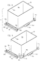
- Fig. 6-9
- Transport units with several or only one pallet on one transport pallet and partially pulled out pallets,
- Fig. 10
- the transport pallet according to Figures 6 and 7 without support plates and pallets,
- Fig. 11
- a support plate with an assigned pallet,
- Fig. 12-14
- the platen with attached pallet in side view, front view and top view and
- Fig. 15
- FIG. 13 shows an enlarged cut-out section corresponding to the cut area through the pallet and transport pallet from FIG. 13.
Die Kunststoff-Spritzgießmaschine, an welcher die Vorrichtung verwirklicht ist, umfaßt eine horizontale Spritzgießeinheit S und eine horizontal angeordnete Werkzeugschließeinheit W. Beide Einheiten sind auf einem Maschinengestell 10 abgestützt. Der Abtransport der beim Spritzbetrieb anfallenden Spritzteile 63 aus der Spritzgießmaschine geschieht mit Hilfe von Paletten 55. Diese werden in einer Füllstation Fs im Bereich der Spritzgießmaschine gefüllt. Im konkreten zeichnerisch dargestellten Ausführungsbeispiel ist die Füllstation wahlweise innerhalb der Spritzgießmaschine (Fig. 1-3) oder außerhalb derselben im Bereich der die Werkzeugschließeinheit begrenzenden Stirnseite angeordnet (Fig. 4,5). Im ersten Fall wird die Palette 55 mit Hilfe einer die Spritzteile 63 aus der geöffneten Spritzgießform entnehmenden Entnahmeeinrichtung H gefüllt. Dabei werden die Spritzteile reihenweise unter Fixierung in Mulden 55g (Fig. 13-15) im Gefolge stufenweiser Bewegungen des Greifers der Entnahmeeinrichtung H quer zur Symmetrieebene s-s abgelegt. Im zweiten Fall wird die Palette 55 mittels eines Förderbandes 18 gefüllt, welches die Spritzteile parallel zur Symmetrieebene s-s transportiert. Das Förderband 18 wird seinerseits vom Greifer der Entnahmeeinrichtung beschickt. Möglich ist aber auch die Füllung der Palette 55 mittels eines Förderbandes, das die aus der geöffneten Spritzgießform ausfallenden Spritzteile aufnimmt (Fig. 5).The plastic injection molding machine on which the device is implemented comprises a horizontal injection molding unit S and a horizontally arranged mold clamping unit W. Both units are supported on a
Die Paletten 55 sind derart ausgebildet, daß sie unter gegenseitiger Zentrierung bedarfsweise zu Stapeleinheiten stapelbar sind. Zur Bereitstellung für die Befüllung in der Füllstation Fs werden sie jedoch in einem Palettenturm 54 einzeln abgestützt. Der Palettenturm 54 ist zwischen der Füllstation Fs und einem weiteren Transportmittel, z.B. einem Transportfahrzeug F (Fig. 2) oder einer Rollenbahn angeordnet und befindet sich an der Rückseite der Spritzgießmaschine außerhalb deren Grundrißfläche. Er ist auf dem Boden abgestellt und überragt die Spritzgießmaschine nach oben. An vertikalen Skelettelementen 54a' des Profilskelettes 54a des Palettenturms 54 ist ein Fahrstuhl 53 mittels Rollen 53d verfahrbar. Der Fahrstuhl 53 ist für die Aufnahme von wenigstens zwei Transporteinheiten T,T' vorbereitet. Der im übrigen während des Füllvorgangs bedarfsweise frei bewegliche Fahrstuhl befindet sich bei der Entnahme der Palette 55 aus als auch bei der Überführung der gefüllten Palette 55 in den Palettenturm 54 in einer Stellung, die zumindest eine Überführung der gefüllten Palette an den Platz in der jeweiligen Transporteinheit T,T' erlaubt, an dem die Palette 55 zuvor aus dieser Transporteinheit entnommen worden ist. Die Überführung der zu befüllenden Paletten 55 in die Füllstation Fs erfolgt lediglich durch eine horizontale Bewegung. Vor Einleitung dieser Bewegung befindet sich der Fahrstuhl nach einer durch eine Wegmeßeinrichtung 52 überwachten vertikalen Bewegung in einer Stellung, in der Palettenführungen 59 der jeweiligen Transporteinheit an Palettenführungen 58 der Füllstation Fs anschließen. Nach der Befüllung werden die Paletten 55 mit der Transportpalette wieder zu einer Transporteinheit verbunden, die anschließend dem Transportfahrzeug übergeben oder von ihm übernommen werden kann.The
Die Antriebseinrichtung 57, die die horizontale Bewegung der Paletten ermöglicht, ohne daß es noch einer weiteren Bewegung des Fahrstuhls bedarf, umfaßt eine unterhalb der sich in der Füllstation befindlichen Palette 55 angeordnete endlose Kette 57b. Ein Mitnehmerstift 57a dieser Kette wird im Gefolge einer halbkreisförmigen Bewegung am Kettenrad 57c mit einer Auflageplatte über eine Quernut 51a' des Kupplungselements 51a gekuppelt. Diese Auflageplatte 51 gleitet auf den Palettenführungen 59 der Transporteinheit und trägt in einer Ausnehmung 51b die jeweiligen Paletten, so daß beliebige Paletten den jeweiligen Auflageplatten zugeordnet werden können. Zwar können auch die Paletten selbst auf den Palettenführungen 58,59 geführt werden, doch trägt dies erheblich zu einer Abnutzung der Paletten bei, die bei Zwischenschaltung von Auflageplatten doch vermieden werden kann. Wie aus Fig. 2 und 3 ersichtlich, sind die Achsen der als Gliederkette ausgebildeten endlosen Kette 57b der Antriebseinrichtung 57 senkrecht angeordnet. Der Mitnehmerstift ist, wie insbesondere aus Fig. 2a ersichtlich, an den Kettengliedern so befestigt, daS er, einen größeren Radius als das Kettenrad beschreibend, nach oben die Kette überragt. Die Kupplung selbst erfolgt dadurch, daß der Mitnehmerstift 57a im Gefolge einer seitlichen Einsteuerung in die im vorliegenden Fall nur zur Hälfte aus vollem Material ausgefräste Quernut eingeführt wird. Um bei der Transportbewegung unnötige Bewegungen der Kette zu vermeiden, sind an der Kette auch Schaltelemente 57e vorgesehen, die bei Annäherung an Endschalter 57f die Bewegung der Kette beenden (Fig. 2,2a).The
Das Profilskelett 54a des Palettenturms 54 besteht aus zwei ungefähr in einer vertikalen Ebene stehenden Skelettelemente 54a', die durch horizontale Skelettelemente miteinander verbunden sind. Dabei ist der Palettenturm durch mehrere Abstützelemente 50 mit der Spritzgießmaschine verbunden. Diese in erster Linie ebene Anordnung des Profilskeletts erlaubt die sowohl rückseitige als auch seitliche Anbindung der Spritzgießmaschine an ein Transportfahrzeug F. Diese Anbindungsmöglichkeit wird konsequent fortgesetzt, als die Hubspindeleinrichtung, die für die Verfahrbarkeit des Fahrstuhls vorgesehen ist, ebenfalls grundsätzlich in der Vertikalprojektion des Profilskeletts 54a angeordnet ist. Eine am Fahrstuhl 53 befestigte Gewindemutter 62b befindet sich im Eingriff mit der rotierenden Gewindespindel 62a der Hubspindeleinrichtung, welche Spindel oben und unten am Profilskelett angelenkt ist. Um die raumsparende Anordnung des Profilskeletts dabei nicht zu stören, ist auch der Motor 62c der Hubspindeleinrichtung nahezu in der Vertikalprojektion des Profilskeletts 54a horizontal angeordnet und treibt die Hubspindel 62a über ein Umlenkgetriebe an.The profile skeleton 54a of the
Um eine möglichst ausreichende Beweglichkeit des Fahrstuhls im Palettenturm zu erreichen, ist der Palettenturm 54 mindestens doppelt so hoch wie der Fahrstuhl 53, in dem mindestens zwei Transporteinheiten T,T' übereinander aufnehmbar sind. Der Fahrstuhl selbst besitzt zwei Aufnahmegabeln 53a für die Transporteinheiten, welche Aufnahmegabeln durch zwei parallele, über wenigstens einen Quersteg 53a'' miteinander verbundene Schienen 53a' gebildet sind. Diese Aufnahmegabeln und somit auch die Transportpaletten 56 der Transporteinheiten T,T' befinden sich dabei stets in einem solchen gegenseitigen Abstand, der mindestens der Höhe einer Transporteinheit entspricht. Als Transporteinheit ist dabei die Einheit von Transportpalette 56 mit einer unterschiedlichen Anzahl von Paletten 55 zu verstehen, die jedoch stets nach Möglichkeit dieselben Außenabmessungen besitzen. Zur Erfassung der in einer Transporteinheit vorgesehenen Anzahl von Paletten 55 sind am Profilskelett 54a Signalgeber 60 angeordnet, deren Anzahl der größtmöglichen Palettenanzahl in der Transporteinheit T,T' und deren gegenseitiger Abstand einer Palette 55 geringster Höhe entspricht. Zur weiteren Absicherung befindet sich an den Paletten 55 ein Strichcode 55k, so daß durch einen an der Füllstation Fs angeordneten Lesesensor 61 die Art der Palette abgetastet werden kann und damit sichergestellt werden kann, daß die Aufnahmemulden 55g der Paletten auch mit den Spritzteilen 63 übereinstimmen.In order to achieve the greatest possible mobility of the elevator in the pallet tower, the
Die Transportpalette selbst besteht, wie insbesondere aus Fig. 10 ersichtlich, aus zwei Führungsschienen 56b, die mit einem Quersteg 56c (im konkreten Ausführungsbeispiel ein Querblech) miteinander verbunden sind. Dieses Grundelement besitzt bereits ein Auflageprofil, das dem Auflageprofil des Spritzwerkzeugs 14a,14b entspricht. Zudem entspricht auch das Querschnittsprofil der Führungsschienen dem Querschnittsprofil der Anlageplatten 14a',14b' des beim Gießformwechsel auf dem Transportfahrzeug zu transportierenden Spritzwerkzeuges. Solch ein Transportfahrzeug F (zeichnerisch nur schematisch in Fig. 2 angedeutet) ist bereits aus der DE 36 17 094 bekannt. Dieses Transportfahrzeug ist dafür vorgesehen, wahlweise Spritzwerkzeuge oder Transporteinheiten zu transportieren und eröffnet damit bedeutende Rationalisierungsmöglichkeiten des Transportsystems der Spritzgießmaschine. Aufgrund der baulichen Voraussetzungen kann eine Übernahmeeinrichrung des Transportfahrzeugs die Transporteinheit aktiv aus dem Palettenturm entnehmen bzw. in diesen rückseitig oder seitlich eingeschieben. Selbstverständlich ist auch eine andere Ausführung denkbar, bei der das Transportfahrzeug selbst passiv die entsprechenden Transporteinheiten übernimmt. Bei der aktiven Übernahme, wie sie im konkreten Ausführungsbeispiel dargestellt ist, sind daher an den Führungsschienen 56b bereits Quernuten 56a angeordnet, in die ein Mitnehmer einer Transportkette des Transportfahrzeuges F einsteuerbar ist. Das aus einem Blech durch Falten und Stanzen hergestellte Grundelement, bestehend aus zusammenhängenden Führungsschienen und Querblech, ist bereits für die baukastenmäßige Aufrüstung vorbereitet. Zu diesem Zweck sind daher Anschlußelemente 56d vorgesehen, an denen bedarfsweise vertikale Tragelemente 56e angeschlossen werden können. In beliebiger Höhe dieser Tragelemente 56e kann dann die je nach Palettenhöhe erforderliche Anzahl von Palettenführungen 59 angebracht werden, wodurch eine große Flexibilität hinsichtlich der Palettengrößen erreicht werden kann.The transport pallet itself, as can be seen in particular from FIG. 10, consists of two
Es ergibt sich somit von selbst, daß die Paletten 55, die in der Transporteinheit T,T' je einzeln abgestützt sind, in Richtung der Spritzachse s-s durch die Tragelemente gesichert sind. Eine Sicherung existiert jedoch aber auch senkrecht zu dieser Richtung durch die federbelasteten Verriegelungselemente 59a. Diese Verriegelungselemente 59a stehen mit Rastöffnungen 51d der Auflageplatten in rastbarer Verbindung, die jedoch bei Horizontalbewegung der Palette durch die Antriebseinrichtung gelöst wird. Ferner weisen sowohl die Palettenführungen 59 als auch die Palettenführungen 58 abgewinkelte Endbereiche 59b auf, die ein problemloses Überführen aus dem Palettenturm in die Füllstation und umgekehrt erlauben.It thus follows that the
Der die Mulden 55g besitzende Boden 55a ist von einer vertikalen Schutzwandung 55f umschlossen. Die Grundfläche des Bodens 55a ist, wie aus den Fign. 11-15 erkennbar, kleiner als der Grundriß der Schutzwand. Dadurch wird eine grundsätzliche Stapelbarkeit der Paletten gewährleistet. Mit dem Zentrierbereich 55d ruhen die Paletten auf den Auflageplatten 51. Zu diesem Zweck sind in den Auflageplatten 51 Ausnehmungen 51b vorgesehen, die dem jeweiligen Zentrierbereich entsprechen. Dennoch können die Paletten 55 außerhalb des Palettenturms und der Transporteinheit in raumsparender Weise gestapelt werden. Die Palette ist daher nicht selbst an der Transportpalette 56 unmittelbar abgestützt, sondern mittelbar über die Auflageplatte 51, wobei die Kontur 51b' der Ausnehmung 51b der Auflageplatte dem oberen Rand 55m einer Palette 55 entspricht. Bedarfsweise können zur Erkennung der Paletten bzw. zur Erkennung der in einer Transporteinheit befindlichen Palettenhöhe Kodiernasen 51c an der Auflageplatte 51 vorgesehen werden, die von den Signalgebern 60 erkannt werden. Zu diesem Zweck ist auch die Gleitschiene 51e in ihren Randbereichen etwas zurück versetzt.The bottom 55a, which has the
Die bei der Variante gemäß Figuren 1-3 innerhalb der Grundrißfläche der Spritzgießmaschine angeordnete Füllstation kann mit geringem Montageaufwand in die Variante gemäß den Fign. 4,5 umgewandelt werden, bei welcher die Füllstation außerhalb der Grundrißfläche der Spritzgießmaschine liegt. Bei dieser Variante liegt die Füllstation vor derjenigen Stirnseite der Spritzgießmaschine, die der Werkzeugschließeinheit W benachbart ist. Der Montageaufwand beschränkt sich dabei im wesentlichen darauf, daß anstelle der Palettenführung 58 auf gleichem Höhen-Niveau ein endloses Förderband 18 in die Spritzgießmaschine eingefügt wird, so daß die Spritzteile 63 unmittelbar auf dem Förderband abgelegt werden können. Somit befindet sich aber die Palettenführung 58 etwa in der gleichen horizontalen Ebene e-e (Fig. 3) wie die Förderfläche des Förderbandes, wobei die Höhe dieser Ebene etwa in der Höhe der Oberkante des Spritzwerkzeugs 14a,14b liegt.The filling station arranged within the layout of the injection molding machine in the variant according to FIGS. 1-3 can be easily converted into the variant according to FIGS. 4,5 are converted, in which the filling station is outside the outline of the injection molding machine. In this variant, the filling station lies in front of that end face of the injection molding machine that is adjacent to the mold clamping unit W. The assembly effort is essentially limited to the fact that instead of the
Dadurch, daß die Paletten in der Transporteinheit einzeln abgestützt sind, können die Paletten problemlos aus der jeweiligen Transporteinheit herausgezogen werden, wobei der Vergleich mit Schubladen naheliegt, die aus einem Schrank herausgezogen werden. Denn wie bei einem Schrank die Schubladen jeweils einzeln unabhängig voneinander und in beliebiger Reihenfolge heraus- und hineingeschoben werden können, eröffnet sich auch hier die Möglichkeit, die Paletten in beliebiger Reihenfolge abzuarbeiten, wobei vorzugsweise von oben nach unten oder von unten nach oben abgearbeitet wird. Die Befüllung verläuft dabei in der Art, daß zunächst eine Palette aus der Transporteinheit T,T' herausgezogen wird, sodann in der Füllstation Fs befüllt wird und anschließend an denselben Platz in der Transporteinheit zurückgeführt wird. Sodann erfolgt eine Absenkung oder ein Anheben des Fahrstuhles, bis die nächste Palette in Bereitschaftsposition ist. Während der Befüllung einer Palette 55 ist jedoch der gesamte Fahrstuhl vertikal frei beweglich, da keine störenden Anschlußelemente oder gar Palettenteile im für eine vertikale Bewegung erforderlichen Bewegungsraum zurückbleiben. Dadurch kann während der Befüllung einer Palette problemlos ein Abtransport einer gefüllten Transporteinheit und die Überführung einer leeren Transporteinheit bewerkstelligt werden. Durch diese vertikale Bewegungsmöglichkeit kommt es nicht darauf an, ob das Transportfahrzeug selbst dafür vorbereitet ist, z.B. mittels einer Hubeinrichtung, die Transporteinheiten in beliebiger Höhe zu übernehmen. Vielmehr braucht das Transportfahrzeug F überhaupt keine Hubeinrichtung aufzuweisen, da dem Fahrstuhl genügend Zeit verbleibt, die befüllte Transporteinheit auf ein Übergabeniveau für das Transportfahrzeug zu überführen.Because the pallets are individually supported in the transport unit, the pallets can be pulled out of the respective transport unit without any problems, the comparison being obvious with drawers which are pulled out of a cabinet. Because, like in a cabinet, the drawers can be pushed out and in individually independently of one another and in any order, the possibility also arises here of processing the pallets in any order, preferably being worked from top to bottom or from bottom to top. The filling is such that a pallet is first pulled out of the transport unit T, T ', then filled in the filling station Fs and then returned to the same place in the transport unit. The elevator is then lowered or raised until the next pallet is in the ready position. During the filling of a
Claims (10)
- Device for removal of injected articles (63) from a plastics injection moulding machine with the aid of pallets (55) which, after removal from a pallet tower (54), are loaded in a filling station (Fs) in the vicinity of the injection moulding machine, and are then transferred from the filling station back into the pallet tower, which has at least one elevator (53), movable on skeleton members (54a') and if necessary freely movable during the loading procedure, for receiving at least two transport units (T;T'), in which the pallets (55), with transport pallets (56) supported on the elevator (53) are connectable to the transport units, characterised in that the transport pallets (56) individually support the pallets (55) on carrier members which, depending on the pallet height, carry a variable number of pallet guide means, and in that the elevator (53), both during removal of the pallet (55) from, and during transfer of the loaded pallet (55) into the pallet tower (54), is in a position permitting transfer of the loaded pallet (55) at least to the same place in the transport unit (T;T') from which the pallet (55) was removed from this transport unit.
- Device according to claim 1, characterised in that the elevator (53) is vertically movable by means of a lifting spindle arrangement (62) supported on the profiled skeleton (54a) of the pallet tower (54)and the threaded nut (62b) of which, attached to the elevator (53), is in engagement with the rotatable lifting spindle (62a) of the lifting spindle arrangement (62), its motor being arranged almost horizontally in the vertical projection of the profiled skeleton (54a) of the pallet tower (54) and driving the lifting spindle (62a) via a reversing gear.
- Device according to one of the preceding claims, characterised in that the pallet tower (54) is at least twice as high as the elevator (53) in which at least two transport units (T;T') can be accommodated one above the other, and on which two take-up forks (53a) for transport units (T;T') are provided, which are formed by two parallel rails (53a') interconnected by at least one crossweb (53a'').
- Device according to one of the preceding claims, characterised in that there are located, on the profiled skeleton (54a) of the pallet tower (54), signal emitters (60) which correspond in number to the largest possible number of pallets in the transport unit (T;T') and whose mutual spacing apart corresponds to a pallet (55) of minimum height, and in that, as required, the pallets (55) are provided with a bar code (55k) which is scanned by reader sensors (61) located at the filling station.
- Device according to one of the preceding claims, characterised in that the transport units (T;T'), for transfer to or take-over by a take-over means, are withdrawable from or retractable into the pallet tower (54) from the rear by a transport means, the transport means being a transport vehicle (F) set up for transporting injection tools (14a, 14b), and in that the transport pallets (56) each have a support profile imitating the support profile of the injection tool (14a, 14b) of the plastics injection moulding machine.
- Device according to claim 5, characterised in that the transport vehicle (F) is provided with the take-over device by means of which a transport unit (T;T') is withdrawable from the pallet tower (54) or is insertable at the rear or laterally therein, there being associated in each case with at least one guide rail (56b) of the transport pallet (56) at least one transverse groove (56a) into which an entrainment means of a transport chain of the transport vehicle can be directed.
- Transport unit, especially for removal of injected articles from a device according to claims 1 to 6, formed from a transport pallet (56) and at least one pallet (55), if necessary connected to the transport pallet, said pallet being separable, for loading with the injected articles coming from the injection moulding machine, from the transport unit, characterised in that the transport pallet (56) has carrier members (56e) which are provided for connection of a number of pallet guides (59) said number varying in dependence on the pallet height, and said guides supporting the pallets (55) individually.
- Transport unit according to claim 7, characterised in that the carrier members (56e) are vertical and if required are removable from the transport pallet (56) at connector members (56d) of the transport pallet.
- Transport unit according to claim 7 or 8, characterised in that the pallet (55) itself is held in a support plate (51) which is guided on the pallet guides (59) of the transport pallet (56) attached to the free-standing vertical carrier members (56e), the support plate (51) having the coupling member (51a) for the drive pin (57a) of the chain (57b) of the drive device (57).
- Transport unit according to one of claims 7-9, characterised in that the transport pallets (56) each have a support profile imitating the support profile of the injection tool (14a, 14b) of the plastics injection moulding machine, said profile being formed by two parallel guide rails (56b) interconnected by at least one crossweb (56b), and whose cross-sectional profile corresponds to the cross-sectional profile of the contact plates (14a', 14b') of an injection tool (14a, 14b) to be transported during mould changeover on to a transport vehicle (F) set up for this purpose, there being located on at least one guide rail (56b) of the transport pallet (56) in each case at least one transverse groove (56a), into which an entrainment means of a transport chain of the transport vehicle can be directed.
Applications Claiming Priority (4)
| Application Number | Priority Date | Filing Date | Title |
|---|---|---|---|
| DE19914120129 DE4120129C2 (en) | 1991-06-19 | 1991-06-19 | Device for the removal of molded parts from a plastic injection molding machine |
| DE4120131 | 1991-06-19 | ||
| DE4120129 | 1991-06-19 | ||
| DE19914120131 DE4120131C1 (en) | 1991-06-19 | 1991-06-19 |
Publications (3)
| Publication Number | Publication Date |
|---|---|
| EP0519318A2 EP0519318A2 (en) | 1992-12-23 |
| EP0519318A3 EP0519318A3 (en) | 1993-05-05 |
| EP0519318B1 true EP0519318B1 (en) | 1997-03-12 |
Family
ID=25904650
Family Applications (1)
| Application Number | Title | Priority Date | Filing Date |
|---|---|---|---|
| EP92109806A Expired - Lifetime EP0519318B1 (en) | 1991-06-19 | 1992-06-11 | Apparatus and transport unit for removing injection moulded articles from a plastic injection moulding machine |
Country Status (6)
| Country | Link |
|---|---|
| US (1) | US5368466A (en) |
| EP (1) | EP0519318B1 (en) |
| JP (1) | JPH0775857B2 (en) |
| AT (1) | ATE149911T1 (en) |
| CA (1) | CA2071339A1 (en) |
| DE (1) | DE59208157D1 (en) |
Cited By (1)
| Publication number | Priority date | Publication date | Assignee | Title |
|---|---|---|---|---|
| DE19848334C2 (en) * | 1998-10-20 | 2001-08-16 | Karl Hehl | Injection molding machine with a handling device |
Families Citing this family (12)
| Publication number | Priority date | Publication date | Assignee | Title |
|---|---|---|---|---|
| JPH0753009A (en) * | 1993-08-12 | 1995-02-28 | Shinkawa Ltd | Magazine conveying device |
| DE4408537A1 (en) * | 1994-03-14 | 1995-09-21 | Leybold Ag | Device for the transport of substrates |
| US5610081A (en) * | 1996-06-03 | 1997-03-11 | Taiwan Semiconductor Manufacturing Company, Ltd | Integrated circuit module fixing method for temperature cycling test |
| US5756133A (en) * | 1996-10-03 | 1998-05-26 | Warner-Lambert Company | Continuous gum base processing with cooling towers |
| US7214286B2 (en) * | 2004-01-30 | 2007-05-08 | Jarden Corporation | Stacked family molding and subsequent assembly process |
| US8701569B2 (en) | 2008-06-20 | 2014-04-22 | Oria Collapsibles, Llc | Pallet design with structural reinforcement |
| US8522694B2 (en) | 2008-06-20 | 2013-09-03 | Oria Collapsibles, Llc | Structural supporting pallet construction with improved perimeter impact absorbing capabilities |
| US8438981B2 (en) | 2008-06-20 | 2013-05-14 | Oria Collapsibles, Llc | Pallet design with buoyant characteristics |
| US8167605B2 (en) * | 2008-06-20 | 2012-05-01 | Oria Collapsibles, Llc | Production assembly and process for mass manufacture of a thermoplastic pallet incorporating a stiffened insert |
| CN110549549B (en) * | 2019-07-10 | 2021-04-09 | 浙江锋龙电气股份有限公司 | Automatic machining equipment for mold inserts |
| JP7358871B2 (en) * | 2019-09-19 | 2023-10-11 | セイコーエプソン株式会社 | Injection molding system and molded product manufacturing method |
| CN111231204B (en) * | 2020-01-10 | 2021-08-31 | 滁州信达自动化设备制造有限公司 | Die change trolley for transporting dies |
Citations (1)
| Publication number | Priority date | Publication date | Assignee | Title |
|---|---|---|---|---|
| US5032053A (en) * | 1986-04-16 | 1991-07-16 | Gesellschaft Fur Roboter Und Logistiktechnologie, Rollotec Ag | Goods handling facility and a method of operating same |
Family Cites Families (14)
| Publication number | Priority date | Publication date | Assignee | Title |
|---|---|---|---|---|
| GB1071096A (en) * | 1964-06-17 | 1967-06-07 | Mazetti Aktiebolag | Improvements relating to moulding machines |
| JPS4894165A (en) * | 1972-03-21 | 1973-12-04 | ||
| JPS57184001A (en) * | 1981-05-06 | 1982-11-12 | Mitsubishi Metal Corp | Automatic aligning apparatus for molded articles |
| US4687403A (en) * | 1983-10-18 | 1987-08-18 | Motoda Electronics Co., Ltd. | Article delivery apparatus |
| JPS60262776A (en) * | 1984-06-12 | 1985-12-26 | Hitachi Seiko Ltd | Stocker for printed boards |
| US4932828A (en) * | 1985-09-04 | 1990-06-12 | Canon Kabushiki Kaisha | Automatic article feeding system |
| JPH0815937B2 (en) * | 1986-06-23 | 1996-02-21 | 松下電器産業株式会社 | Separation and positioning device for component storage members |
| US5203661A (en) * | 1987-08-05 | 1993-04-20 | Canon Kabushiki Kaisha | Handling device for articles or containers |
| DE3830964A1 (en) * | 1988-09-12 | 1990-03-22 | Karl Hehl | INJECTION MOLDING MACHINE WITH A DEVICE FOR REMOVING THE INJECTION PARTS FROM THE INJECTION TOOL |
| GB8807666D0 (en) * | 1988-03-31 | 1988-05-05 | Wadkin Public Ltd Co | Fixture pallet changing apparatus |
| DE3830958A1 (en) * | 1988-09-12 | 1990-03-22 | Karl Hehl | DEVICE FOR THE REMOVAL OF INJECTION PARTS FROM AN INJECTION MOLDING MACHINE |
| JPH0292512A (en) * | 1988-09-29 | 1990-04-03 | Teijin Seiki Co Ltd | Mechanism for elevating pallet in insert molding machine |
| US5104277A (en) * | 1989-04-06 | 1992-04-14 | Hewlett-Packard Company | Method and apparatus for automatically changing printed circuit board test fixtures |
| JP2864041B2 (en) * | 1990-05-02 | 1999-03-03 | 株式会社進興製作所 | Automatic pallet changing device and automatic pallet changing method |
-
1992
- 1992-06-11 AT AT92109806T patent/ATE149911T1/en not_active IP Right Cessation
- 1992-06-11 EP EP92109806A patent/EP0519318B1/en not_active Expired - Lifetime
- 1992-06-11 DE DE59208157T patent/DE59208157D1/en not_active Expired - Fee Related
- 1992-06-16 CA CA002071339A patent/CA2071339A1/en not_active Abandoned
- 1992-06-19 JP JP4186274A patent/JPH0775857B2/en not_active Expired - Lifetime
- 1992-06-19 US US07/901,610 patent/US5368466A/en not_active Expired - Fee Related
Patent Citations (1)
| Publication number | Priority date | Publication date | Assignee | Title |
|---|---|---|---|---|
| US5032053A (en) * | 1986-04-16 | 1991-07-16 | Gesellschaft Fur Roboter Und Logistiktechnologie, Rollotec Ag | Goods handling facility and a method of operating same |
Cited By (1)
| Publication number | Priority date | Publication date | Assignee | Title |
|---|---|---|---|---|
| DE19848334C2 (en) * | 1998-10-20 | 2001-08-16 | Karl Hehl | Injection molding machine with a handling device |
Also Published As
| Publication number | Publication date |
|---|---|
| JPH05261760A (en) | 1993-10-12 |
| CA2071339A1 (en) | 1992-12-20 |
| US5368466A (en) | 1994-11-29 |
| EP0519318A3 (en) | 1993-05-05 |
| ATE149911T1 (en) | 1997-03-15 |
| EP0519318A2 (en) | 1992-12-23 |
| JPH0775857B2 (en) | 1995-08-16 |
| DE59208157D1 (en) | 1997-04-17 |
Similar Documents
| Publication | Publication Date | Title |
|---|---|---|
| EP0519318B1 (en) | Apparatus and transport unit for removing injection moulded articles from a plastic injection moulding machine | |
| EP0359014B1 (en) | Apparatus for removing moulded articles from a plastic injection-moulding machine | |
| DE164062T1 (en) | DEVICE FOR CHANGING A MOLD IN A PRESS, IN PARTICULAR IN AN INJECTION MOLDING MACHINE. | |
| EP1731453B1 (en) | Method and device for stacking deep drawn articles | |
| DE2543621A1 (en) | CAN CHANGER DEVICE | |
| DE19727749A1 (en) | Robot for product demoulding | |
| EP0359013B1 (en) | Plastic injection moulding machine | |
| EP0666162A1 (en) | Apparatus for making hollow articles from thermoplastic material by extrusion-blow moulding | |
| EP0246398B1 (en) | Mould exchange apparatus for a group of plastic injection-moulding machines | |
| EP0579937B1 (en) | Vacuum forming machine for simultaneously forming and welding two plastic sheets | |
| EP0321461B1 (en) | Injection molding plant | |
| EP0255852B1 (en) | Mould exchanging apparatus for a plastic injection moulding machine | |
| WO2021228535A1 (en) | Modular plant for producing food products | |
| DE4120129C2 (en) | Device for the removal of molded parts from a plastic injection molding machine | |
| DE102007038622A1 (en) | stack cell | |
| DE3822363C2 (en) | ||
| EP0703060B1 (en) | Method for discharging and depositing or stacking of deepdrawn moulded objects and apparatus for carrying out such a method | |
| EP0869084A2 (en) | Tray for conveying material and device for handling the tray | |
| DE4137169C2 (en) | Conveyor for bar stock | |
| DE4120131C1 (en) | ||
| DE19936600B4 (en) | Method and device for changing a mold and for replacing a material pallet in a vacuum forming machine | |
| EP0890880B1 (en) | Device for processing printing plates | |
| DE4121844C2 (en) | Device for picking up and removing catch boxes for parts from series production | |
| DE1286964B (en) | Device for moving stacks of boxes to be transported on pallets or the like. | |
| DE2541620A1 (en) | METHOD AND EQUIPMENT FOR HANDLING OR CONTAINER LOADING |
Legal Events
| Date | Code | Title | Description |
|---|---|---|---|
| PUAI | Public reference made under article 153(3) epc to a published international application that has entered the european phase |
Free format text: ORIGINAL CODE: 0009012 |
|
| AK | Designated contracting states |
Kind code of ref document: A2 Designated state(s): AT CH DE ES FR GB IT LI NL PT |
|
| PUAL | Search report despatched |
Free format text: ORIGINAL CODE: 0009013 |
|
| AK | Designated contracting states |
Kind code of ref document: A3 Designated state(s): AT CH DE ES FR GB IT LI NL PT |
|
| 17P | Request for examination filed |
Effective date: 19931103 |
|
| 17Q | First examination report despatched |
Effective date: 19950628 |
|
| GRAG | Despatch of communication of intention to grant |
Free format text: ORIGINAL CODE: EPIDOS AGRA |
|
| GRAH | Despatch of communication of intention to grant a patent |
Free format text: ORIGINAL CODE: EPIDOS IGRA |
|
| GRAH | Despatch of communication of intention to grant a patent |
Free format text: ORIGINAL CODE: EPIDOS IGRA |
|
| GRAA | (expected) grant |
Free format text: ORIGINAL CODE: 0009210 |
|
| AK | Designated contracting states |
Kind code of ref document: B1 Designated state(s): AT CH DE ES FR GB IT LI NL PT |
|
| PG25 | Lapsed in a contracting state [announced via postgrant information from national office to epo] |
Ref country code: NL Free format text: LAPSE BECAUSE OF FAILURE TO SUBMIT A TRANSLATION OF THE DESCRIPTION OR TO PAY THE FEE WITHIN THE PRESCRIBED TIME-LIMIT Effective date: 19970312 Ref country code: ES Free format text: THE PATENT HAS BEEN ANNULLED BY A DECISION OF A NATIONAL AUTHORITY Effective date: 19970312 |
|
| REF | Corresponds to: |
Ref document number: 149911 Country of ref document: AT Date of ref document: 19970315 Kind code of ref document: T |
|
| REG | Reference to a national code |
Ref country code: CH Ref legal event code: EP |
|
| REG | Reference to a national code |
Ref country code: CH Ref legal event code: NV Representative=s name: LUCHS & PARTNER PATENTANWAELTE |
|
| REF | Corresponds to: |
Ref document number: 59208157 Country of ref document: DE Date of ref document: 19970417 |
|
| ITF | It: translation for a ep patent filed |
Owner name: CALVANI SALVI E VERONELLI S.R.L. |
|
| PG25 | Lapsed in a contracting state [announced via postgrant information from national office to epo] |
Ref country code: PT Effective date: 19970612 |
|
| ET | Fr: translation filed | ||
| NLV1 | Nl: lapsed or annulled due to failure to fulfill the requirements of art. 29p and 29m of the patents act | ||
| GBT | Gb: translation of ep patent filed (gb section 77(6)(a)/1977) |
Effective date: 19970714 |
|
| PLBE | No opposition filed within time limit |
Free format text: ORIGINAL CODE: 0009261 |
|
| STAA | Information on the status of an ep patent application or granted ep patent |
Free format text: STATUS: NO OPPOSITION FILED WITHIN TIME LIMIT |
|
| 26N | No opposition filed | ||
| PGFP | Annual fee paid to national office [announced via postgrant information from national office to epo] |
Ref country code: GB Payment date: 19980527 Year of fee payment: 7 |
|
| PGFP | Annual fee paid to national office [announced via postgrant information from national office to epo] |
Ref country code: FR Payment date: 19980617 Year of fee payment: 7 |
|
| PGFP | Annual fee paid to national office [announced via postgrant information from national office to epo] |
Ref country code: AT Payment date: 19980623 Year of fee payment: 7 |
|
| PGFP | Annual fee paid to national office [announced via postgrant information from national office to epo] |
Ref country code: CH Payment date: 19980701 Year of fee payment: 7 |
|
| PG25 | Lapsed in a contracting state [announced via postgrant information from national office to epo] |
Ref country code: GB Free format text: LAPSE BECAUSE OF NON-PAYMENT OF DUE FEES Effective date: 19990611 Ref country code: AT Free format text: LAPSE BECAUSE OF NON-PAYMENT OF DUE FEES Effective date: 19990611 |
|
| PG25 | Lapsed in a contracting state [announced via postgrant information from national office to epo] |
Ref country code: LI Free format text: LAPSE BECAUSE OF NON-PAYMENT OF DUE FEES Effective date: 19990630 Ref country code: FR Free format text: THE PATENT HAS BEEN ANNULLED BY A DECISION OF A NATIONAL AUTHORITY Effective date: 19990630 Ref country code: CH Free format text: LAPSE BECAUSE OF NON-PAYMENT OF DUE FEES Effective date: 19990630 |
|
| GBPC | Gb: european patent ceased through non-payment of renewal fee |
Effective date: 19990611 |
|
| REG | Reference to a national code |
Ref country code: CH Ref legal event code: PL |
|
| REG | Reference to a national code |
Ref country code: FR Ref legal event code: ST |
|
| PGFP | Annual fee paid to national office [announced via postgrant information from national office to epo] |
Ref country code: DE Payment date: 20010410 Year of fee payment: 10 |
|
| PG25 | Lapsed in a contracting state [announced via postgrant information from national office to epo] |
Ref country code: DE Free format text: LAPSE BECAUSE OF NON-PAYMENT OF DUE FEES Effective date: 20030101 |
|
| PG25 | Lapsed in a contracting state [announced via postgrant information from national office to epo] |
Ref country code: IT Free format text: LAPSE BECAUSE OF NON-PAYMENT OF DUE FEES Effective date: 20050611 |