EP0518546A2 - Herzschrittmacher mit verringertem Strom - Google Patents
Herzschrittmacher mit verringertem Strom Download PDFInfo
- Publication number
- EP0518546A2 EP0518546A2 EP92305070A EP92305070A EP0518546A2 EP 0518546 A2 EP0518546 A2 EP 0518546A2 EP 92305070 A EP92305070 A EP 92305070A EP 92305070 A EP92305070 A EP 92305070A EP 0518546 A2 EP0518546 A2 EP 0518546A2
- Authority
- EP
- European Patent Office
- Prior art keywords
- pacing
- heart muscle
- patient
- individual
- current
- Prior art date
- Legal status (The legal status is an assumption and is not a legal conclusion. Google has not performed a legal analysis and makes no representation as to the accuracy of the status listed.)
- Granted
Links
Images


Classifications
-
- A—HUMAN NECESSITIES
- A61—MEDICAL OR VETERINARY SCIENCE; HYGIENE
- A61N—ELECTROTHERAPY; MAGNETOTHERAPY; RADIATION THERAPY; ULTRASOUND THERAPY
- A61N1/00—Electrotherapy; Circuits therefor
- A61N1/18—Applying electric currents by contact electrodes
- A61N1/32—Applying electric currents by contact electrodes alternating or intermittent currents
- A61N1/323—Interference currents, i.e. treatment by several currents summed in the body
-
- A—HUMAN NECESSITIES
- A61—MEDICAL OR VETERINARY SCIENCE; HYGIENE
- A61N—ELECTROTHERAPY; MAGNETOTHERAPY; RADIATION THERAPY; ULTRASOUND THERAPY
- A61N1/00—Electrotherapy; Circuits therefor
- A61N1/18—Applying electric currents by contact electrodes
- A61N1/32—Applying electric currents by contact electrodes alternating or intermittent currents
- A61N1/36—Applying electric currents by contact electrodes alternating or intermittent currents for stimulation
- A61N1/362—Heart stimulators
- A61N1/3625—External stimulators
Definitions
- the present invention relates to a cardiac pacing apparatus, and in particular, to an apparatus and method for providing low-current cardiac pacing signals.
- Atrial ventricular (AV) delay the atrial ventricular delay
- the atrial and ventricular contractions begin with a wave of electrical excitation that originates in the right atrium and spreads to the left atrium. This excitation of the cardiac muscle then spreads to the AV node, which delays its passage to the ventricles.
- Atrial excitations begin every 400-1,000 milliseconds at a metabolically-determined frequency known as the sinus rate.
- sinus rate a metabolically-determined frequency known as the sinus rate.
- electrical excitation signals are either not properly produced or do not reach the heart muscle. In either case, the heart will not pump blood properly.
- the cure for such a heart condition when permanent, has been to implant an internal cardiac pacemaker that electrically supplies the necessary excitation pacing signals through a set of electrodes connected directly to the heart.
- Such electrodes may include a single electrode or pairs of electrodes that deliver the pacing currents to various areas of the heart muscle.
- pacing signals may be applied externally using a cardiac pacemaker in order to stay alive.
- Such pacing signals may be applied continuously if the heart is completely malfunctioning, or intermittently if it is only occasionally malfunctioning.
- External cardiac pacers are also used to restore a temporarily malfunctioning heart to normal operation, as can occur, for example, after electrical shock.
- an external pacer includes a set of electrodes that are placed in electrical contact with the patient's chest. The pacer delivers an electric current large enough to stimulate the heart muscle and contract it, thereby pumping blood.
- an external cardiac pacing apparatus for providing a total cardiac pacing signal to a patient's heart muscle.
- An electrical current source is coupled to a plurality of electrode pairs, which are attachable to the patient.
- the electrical current source provides each of the electrode pairs with an individual electrical current.
- the individual electrical currents cooperatively form the total cardiac pacing signal.
- the magnitude of the electric pacing current supplied by the current source to each of the electrode pairs is less than the total pacing current required to cause contraction of a heart muscle in order to reduce patient discomfort.
- FIGURE 1 is a first embodiment of a reduced current cardiac pacing apparatus according the present invention, shown generally at reference numeral 1.
- a set of pacing electrodes 5 comprises a plurality of positive electrodes 5a, 5b, and 5c and a plurality of negative electrodes 5a', 5b' and 5c'.
- an impedance Ra exists between electrodes 5a and 5a'
- an impedance Rc exists between electrodes 5c and 5c'.
- a common pacing current source 12 supplies a pacing current to each of the parallely-connected electrode pairs 5a and 5a', 5b and 5b', and 5c and 5c'.
- the pacing current applied to the plurality of electrodes will divide among the electrode pairs according the magnitude of the impedances Ra, Rb, and Rc. If the magnitude of these impedances is relatively equal, then the pacing current will divide equally among the electrode pairs.
- FIGURE 2 is a diagram showing a second embodiment of a reduced current cardiac pacing apparatus 10 according to the present invention.
- Apparatus 10 comprises a plurality of electrode pairs 20 and 22, each of which further comprises a pair of positive electrodes 20a and 22a and a corresponding pair of negative electrodes 20b and 22b, respectively.
- electrode pair is assumed to include a positive electrode and a negative electrode.
- electrode pairs 20 and 22 are placed on the thoracic cavity of a patient 15 such that positive electrode 20a lies in a position generally superior to the right atrium of a heart muscle 17 and negative electrode 20b is placed in a position generally inferior to the left ventricle of heart muscle 17.
- positive electrode 22a is placed in a position generally superior to the left ventricle of heart muscle 17 and negative electrode 22b lies in a position generally inferior to the right ventricle of heart muscle 17.
- negative electrode 22b lies in a position generally inferior to the right ventricle of heart muscle 17.
- the most effective placement of the electrodes was found to be on the front of the patient. If more than two electrode pairs are used, it may be preferable to place electrodes having one polarity on the back of the patient in a position above the heart muscle and the electrodes having the opposite polarity on the front of the patient below the heart muscle.
- An electric current is provided to each of electrode pairs 20 and 22 from a current pacing apparatus 24.
- Current pacing apparatus 24 includes a plurality of electrically isolated current sources (not separately shown) that deliver electric pacing currents to electrode pairs 20 and 22. Because the current sources that provide the pacing currents to positive electrodes 20a and 22a are electrically isolated, all the current that enters positive electrode 20a will flow to negative electrode 20b. This is because an electric circuit must always follow a closed path. Similarly, any current that enters positive electrode 22a must flow to negative electrode 22b.
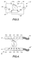
- FIGURE 3 shows an electrical schematic diagram of an electrically isolated current source 30 that delivers a pacing current to the pair of electrodes 20a and 20b.
- Isolated current source 30 delivers an individual pacing current to positive electrode 20a via a lead 26.
- the individual pacing current flows from positive electrode 20a over heart muscle 17 to negative electrode 20b and returns to isolated current source 30 via a lead 26'.
- An electrically isolated current source 32 similarly provides an individual pacing current to the pair of electrodes 22a and 22b via a lead 28 and a lead 28'.
- the individual pacing current flows from positive electrode 22a across heart muscle 17 to negative electrode 22b and returns to isolated current source 32 via lead 28'.
- the level of current provided by isolated current sources 30 and 32 is chosen to collectively cause contraction of heart muscle 17. However, the magnitude of the individual pacing currents supplied by isolated current sources 30 and 32 is chosen to avoid causing discomfort or burning to the patient.
- the total current delivered to the patient maybe more than the minimum level needed to contract the heart muscle.
- the individual pacing current flowing between positive and negative electrodes that comprise an electrode pair should remain less than the level of current needed to contract the heart muscle in order to reduce patient discomfort.
- the benefit of using electrically isolated current sources can be seen by comparing the isolated current sources and electrode configuration of FIGURE 2 with the current source and electrode configuration shown in FIGURE 1.
- the set of pacing electrodes 5 are driven in parallel by a common pacing current source 12. Because positive electrodes 5a, 5b, and 5c and negative electrodes 5a', 5b', and 5c' are connected in parallel, more current will tend to flow between the positive electrode and negative electrode having the lowest inter-electrode impedance. If one of the impedances Ra, Rb, or Rc is relatively low, the electrode pair associated with that impedance will carry a relatively high proportion of the overall current delivered to the heart.
- FIGURE 4 shows an alternative embodiment of a reduced current cardiac pacing apparatus, generally at reference numeral 40.
- Cardiac pacing apparatus 40 includes two electrode strips 42 and 44. Electrode strips 42 and 44 respectively comprise a plurality of positive electrodes 42a, 42b, 42c, 42d, and 42e and corresponding negative electrodes 44a, 44b, 44c, 44d, and 44e.
- a plurality of electrically isolated current sources (not shown) are connected to electrode strip 42 and 44 via leads 46 and 46'. The isolated current sources are connected such that a plurality of individual pacing currents flow diagonally across heart muscle 17. For example, an individual pacing current flows between positive electrode 42a and negative electrode 44a.
- each electrode pair e.g., 42b and 44b, carries an individual pacing current of smaller magnitude than the total pacing current required to contract the heart muscle. Yet, the total current delivered to all of the electrodes may be greater than the current needed to contract the heart muscle.
- the preferred embodiments have been disclosed as dividing the total required pacing current equally between electrode pairs, it is recognized that any division of the required total pacing current is possible as long as each electrode pair conveys a level of current that will reduce patient burning or discomfort.
- FIGURE 5 is a block diagram of a cardiac pacing apparatus 24 that incorporates the present invention.
- Cardiac pacing apparatus 24 may be a stand-alone unit or incorporated within either a multiple function pacing/defibrillator or electrocardiogram (ECG) monitoring unit.
- a set of monitoring cables 50 carries electrical signals from the patient to an ECG monitor 52 via a lead 54.
- ECG monitor 52 provides ECG signals to a demand pacing controller 56 via a lead 58 or to an output port 60 via a lead 62.
- An input port 64 is connected to demand pacing controller 56 by a lead 70 to enable an operator to selectively operate cardiac pacing apparatus 24 in either a demand mode or a continuous pacing mode.
- a pacing current signal is applied to the heart at a continuous rate regardless of the ECG signal of the patient.
- pacing current signals are applied only in the absence of spontaneous ECG signals generated by the heart muscle.
- Demand pacing controller 56 is typically used to initiate the application of a pacing current signal to the heart muscle upon the occurrence or non-occurrence of a particular portion of a ECG signal (not shown). For example, if the heart is working intermittently, i.e., the patient's body is sometimes generating the proper ECG signals, but not reliably, then demand pacing controller 56 delivers appropriate pacing current signals in order to ensure that the heart operates properly. Should the natural ECG signal fail, demand pacing controller 56 provides a pacing current signal to the patient's heart at a time when the heart muscle would have received its own spontaneous ECG signal.
- a pulse rate controller 66 controls the rate at which pacing current signals are delivered to the heart in response to a manual input or possibly a signal from demand pacing controller 56 transmitted over a lead 68. For example, a signal transmitted from demand pacing controller 56 to pulse rate controller 66 may instruct the pulse rate controller to increase or decrease the rate at which pacing current signals are delivered to the heart.
- input port 64 is connected to pulse rate controller 66 via lead 70 to provide means for entry of a manual setting of the rate at which pacing current signals are delivered to the heart.
- a current level controller 72 controls the magnitude of the individual pacing currents delivered to each of the electrode pairs. Because patients may require different levels of pacing current to get the heart to beat properly, the magnitude of each of the individual pacing currents may need to be adjusted. Should the total pacing current delivered to the electrode pairs collectively be too small to contract the heart muscle, the level of current being delivered can be increased manually by a signal from input port 64 that is transmitted to current level controller 72 via lead 70. Alternatively, demand pacing controller 56 may be programmed to detect that the heart has not responded as desired. As a result, demand pacing controller 56 signals current level controller 72 via a lead 74 to increase the magnitude of the individual pacing currents delivered.
- a pacing synchronizing circuit 76 controls the operation of a plurality of electrically isolated current sources 78a-78n.
- the plurality of electrically isolated current sources 78a-78n provide pacing current signals to a plurality of pacing electrode cables 80a-80n, respectively.
- Pacing synchronizing circuit 76 is provided to ensure that the pacing current signals delivered to electrode cables 80a-80n arrive at the heart muscle at the correct time to collectively restore the heart to normal operation.
- Pacing synchronizing circuit 76 Another use for pacing synchronizing circuit 76 is to vary the individual pacing currents that are delivered to the electrode pairs to vary the direction of the total pacing current. By altering the time at which the individual pacing currents are delivered to the electrode pairs or the magnitude of the individual pacing currents, it is possible to change the direction of the total pacing current flowing across the heart muscle. Pacing synchronizing circuit 76 can be programmed, based on clinical data, to alter the direction of the total pacing currents delivered to the electrode pairs to test a heart muscle's susceptibility to various cardiac arrythmias.
- cardiac pacing unit 24 delivers a plurality of individual pacing currents to a patient.
- Each pacing current has a magnitude less than the total amount of current needed to contract a heart muscle.
- the individual pacing currents flow across the heart muscle, they add to produce a total pacing current having sufficient magnitude to contract the heart muscle. Patient discomfort or burning is reduced by keeping the magnitude of the individual pacing currents low.
Landscapes
- Health & Medical Sciences (AREA)
- Engineering & Computer Science (AREA)
- Biomedical Technology (AREA)
- Nuclear Medicine, Radiotherapy & Molecular Imaging (AREA)
- Radiology & Medical Imaging (AREA)
- Life Sciences & Earth Sciences (AREA)
- Animal Behavior & Ethology (AREA)
- General Health & Medical Sciences (AREA)
- Public Health (AREA)
- Veterinary Medicine (AREA)
- Cardiology (AREA)
- Heart & Thoracic Surgery (AREA)
- Electrotherapy Devices (AREA)
- Compositions Of Oxide Ceramics (AREA)
Applications Claiming Priority (2)
| Application Number | Priority Date | Filing Date | Title |
|---|---|---|---|
| US71316991A | 1991-06-11 | 1991-06-11 | |
| US713169 | 1991-06-11 |
Publications (3)
| Publication Number | Publication Date |
|---|---|
| EP0518546A2 true EP0518546A2 (de) | 1992-12-16 |
| EP0518546A3 EP0518546A3 (en) | 1993-01-27 |
| EP0518546B1 EP0518546B1 (de) | 1997-08-27 |
Family
ID=24865058
Family Applications (1)
| Application Number | Title | Priority Date | Filing Date |
|---|---|---|---|
| EP92305070A Expired - Lifetime EP0518546B1 (de) | 1991-06-11 | 1992-06-03 | Herzschrittmacher mit verringertem Strom |
Country Status (7)
| Country | Link |
|---|---|
| US (1) | US5330506A (de) |
| EP (1) | EP0518546B1 (de) |
| JP (1) | JPH06238010A (de) |
| AT (1) | ATE157271T1 (de) |
| AU (1) | AU1736392A (de) |
| CA (1) | CA2070893A1 (de) |
| DE (1) | DE69221779T2 (de) |
Cited By (4)
| Publication number | Priority date | Publication date | Assignee | Title |
|---|---|---|---|---|
| WO1994019053A1 (en) * | 1993-02-19 | 1994-09-01 | Medtronic, Inc. | Medical stimulator with multiple operational amplifier output stimulation circuits |
| GB2280377A (en) * | 1993-07-19 | 1995-02-01 | Zmd Corp | Method and apparatus for transcutaneous electrical cardiac pacing |
| EP0776678A1 (de) * | 1995-11-30 | 1997-06-04 | Hewlett-Packard Company | System zur Abgabe von transkutanen Herzreizungenmit transkutanen elektrischen Nervenstimuli |
| US9174061B2 (en) | 2003-11-13 | 2015-11-03 | Zoll Medical Corporation | Multi-path transthoracic defibrillation and cardioversion |
Families Citing this family (21)
| Publication number | Priority date | Publication date | Assignee | Title |
|---|---|---|---|---|
| US6185457B1 (en) * | 1994-05-31 | 2001-02-06 | Galvani, Ltd. | Method and apparatus for electrically forcing cardiac output in an arrhythmia patient |
| US6853859B1 (en) * | 1994-05-31 | 2005-02-08 | Galvani, Ltd. | Electrical cardiac output forcer |
| DE19519237C2 (de) * | 1995-05-24 | 2001-06-21 | Siemens Ag | Vorrichtung zur Erfassung stimulierter Aktionsströme des Herzens |
| US6148233A (en) * | 1997-03-07 | 2000-11-14 | Cardiac Science, Inc. | Defibrillation system having segmented electrodes |
| US6091989A (en) * | 1998-04-08 | 2000-07-18 | Swerdlow; Charles D. | Method and apparatus for reduction of pain from electric shock therapies |
| CA2239673A1 (en) * | 1998-06-04 | 1999-12-04 | Christer Sinderby | Automatic adjustment of applied levels of ventilatory support and extrinsic peep by closed-loop control of neuro-ventilatory efficiency |
| US9248306B2 (en) | 1999-09-30 | 2016-02-02 | Physio-Control, Inc. | Pulse detection apparatus, software, and methods using patient physiological signals |
| US6440082B1 (en) * | 1999-09-30 | 2002-08-27 | Medtronic Physio-Control Manufacturing Corp. | Method and apparatus for using heart sounds to determine the presence of a pulse |
| US20030109790A1 (en) * | 2001-12-06 | 2003-06-12 | Medtronic Physio-Control Manufacturing Corp. | Pulse detection method and apparatus using patient impedance |
| US7130682B2 (en) | 2000-12-26 | 2006-10-31 | Cardiac Pacemakers, Inc. | Pacing and sensing vectors |
| US6754531B1 (en) * | 2001-10-19 | 2004-06-22 | Pacesetter, Inc. | Anti-tachycardia pacing methods and devices |
| US7110815B2 (en) * | 2002-05-06 | 2006-09-19 | Cardiac Pacemakers, Inc. | System and method for providing temporary stimulation therapy to optimize chronic electrical performance for electrodes used in conjunction with a cardiac rhythm management system |
| US20040116969A1 (en) * | 2002-08-26 | 2004-06-17 | Owen James M. | Pulse detection using patient physiological signals |
| JP4889939B2 (ja) | 2003-11-13 | 2012-03-07 | ゾール メディカル コーポレイション | 経胸腔式除細動器 |
| US7167746B2 (en) * | 2004-07-12 | 2007-01-23 | Ats Medical, Inc. | Anti-coagulation and demineralization system for conductive medical devices |
| US8401637B2 (en) * | 2004-11-24 | 2013-03-19 | Galvani, Ltd. | Medium voltage therapy applications in treating cardiac arrest |
| DE102005021581A1 (de) * | 2005-05-10 | 2006-11-23 | Universitätsklinikum Freiburg | Aufnahmemodul für ein in einen menschlichen Körper implantierbares Gerät |
| US20080161705A1 (en) * | 2006-12-29 | 2008-07-03 | Podmore Jonathan L | Devices and methods for ablating near AV groove |
| DK2318092T3 (en) * | 2008-07-22 | 2018-03-12 | Narayanan Lakshmanan | Non-invasive temporary interference stimulator |
| US8483822B1 (en) | 2009-07-02 | 2013-07-09 | Galvani, Ltd. | Adaptive medium voltage therapy for cardiac arrhythmias |
| US8750990B1 (en) | 2012-12-12 | 2014-06-10 | Galvani, Ltd. | Coordinated medium voltage therapy for improving effectiveness of defibrillation therapy |
Family Cites Families (24)
| Publication number | Priority date | Publication date | Assignee | Title |
|---|---|---|---|---|
| FR1237702A (fr) * | 1953-07-11 | 1960-08-05 | Perfectionnements aux appareils électro-médicaux | |
| GB1207244A (en) * | 1968-04-08 | 1970-09-30 | Mikhail Ilich Kuzin | Apparatus for controlled inhibition of the central nervous system |
| FR2139726B1 (de) * | 1968-07-16 | 1975-08-22 | Nemectron Gmbh | |
| US3774620A (en) * | 1971-06-14 | 1973-11-27 | Nemectron Gmbh | Electromedicinal apparatus for interference current therapy |
| US3895639A (en) * | 1971-09-07 | 1975-07-22 | Rodler Ing Hans | Apparatus for producing an interference signal at a selected location |
| US3958577A (en) * | 1971-11-22 | 1976-05-25 | Rodler Ing Hans | Apparatus for treatment with sum currents |
| US3789854A (en) * | 1972-04-06 | 1974-02-05 | Medcor Inc | Dual mode cardiac pacer power source |
| US4148321A (en) * | 1973-11-26 | 1979-04-10 | Wyss Oscar A M | Apparatuses and methods for therapeutic treatment and active massages of muscles |
| FR2257312A1 (en) * | 1974-01-16 | 1975-08-08 | Zacouto Fred | Electromedical heart treatment appts. - generates electric field between peripheral electrode and one implanted in heart cavity |
| US3937226A (en) * | 1974-07-10 | 1976-02-10 | Medtronic, Inc. | Arrhythmia prevention apparatus |
| US4088140A (en) * | 1976-06-18 | 1978-05-09 | Medtronic, Inc. | Demand anti-arrhythmia pacemaker |
| US4094310A (en) * | 1976-10-04 | 1978-06-13 | American Optical Corporation | Apparatus for enhanced display of physiological waveforms and for defibrillation |
| US4280504A (en) * | 1979-01-16 | 1981-07-28 | Firma Somartec S.A. | Device for treatment with interference currents |
| US4401121A (en) * | 1979-01-16 | 1983-08-30 | Firma Somartec S.A. | Device for treatment with interference currents |
| US4576170A (en) * | 1980-07-09 | 1986-03-18 | Micro-Circuits Company | Heart monitor and defibrillator device |
| US4467807A (en) * | 1981-11-23 | 1984-08-28 | Medtronic, Inc. | Rate adaptive demand pacemaker |
| GB2110935B (en) * | 1981-11-23 | 1985-06-26 | Ross Holman Zoll | External noninvasive electric cardiac stimulation |
| US4462406A (en) * | 1982-05-05 | 1984-07-31 | Cordis Corporation | Dual channel isolation system for cardiac pacer |
| US4708145A (en) * | 1982-06-01 | 1987-11-24 | Medtronic, Inc. | Sequential-pulse, multiple pathway defibrillation method |
| US4550370A (en) * | 1982-10-29 | 1985-10-29 | Medtronic, Inc. | Pacemaker programmer with telemetric functions |
| DE3247264A1 (de) * | 1982-12-21 | 1984-06-28 | Siemens AG, 1000 Berlin und 8000 München | Bifokaler herzschrittmacher mit zwei unipolaren elektroden |
| US4549548A (en) * | 1983-09-14 | 1985-10-29 | Vitafin N.V. | Pacemaker system with automatic event-programmed switching between unipolar and bipolar operation |
| DE3535534A1 (de) * | 1985-10-04 | 1987-04-09 | Siemens Ag | Herzschrittmacher |
| IT1216198B (it) * | 1986-11-20 | 1990-02-22 | C B Bioelettronica Srl | Ne cardiaca transesofagea con apparecchiatura per la stimolaziominimizzazione della soglia di stimolazione e metodo relativo a tale stimolazione |
-
1992
- 1992-06-02 AU AU17363/92A patent/AU1736392A/en not_active Abandoned
- 1992-06-03 EP EP92305070A patent/EP0518546B1/de not_active Expired - Lifetime
- 1992-06-03 DE DE69221779T patent/DE69221779T2/de not_active Expired - Fee Related
- 1992-06-03 AT AT92305070T patent/ATE157271T1/de not_active IP Right Cessation
- 1992-06-10 CA CA002070893A patent/CA2070893A1/en not_active Abandoned
- 1992-06-11 JP JP4150999A patent/JPH06238010A/ja not_active Withdrawn
-
1993
- 1993-09-21 US US08/125,080 patent/US5330506A/en not_active Expired - Lifetime
Cited By (10)
| Publication number | Priority date | Publication date | Assignee | Title |
|---|---|---|---|---|
| US5431688A (en) * | 1990-06-12 | 1995-07-11 | Zmd Corporation | Method and apparatus for transcutaneous electrical cardiac pacing |
| US5370665A (en) * | 1990-08-10 | 1994-12-06 | Medtronic, Inc. | Medical stimulator with multiple operational amplifier output stimulation circuits |
| WO1994019053A1 (en) * | 1993-02-19 | 1994-09-01 | Medtronic, Inc. | Medical stimulator with multiple operational amplifier output stimulation circuits |
| GB2280377A (en) * | 1993-07-19 | 1995-02-01 | Zmd Corp | Method and apparatus for transcutaneous electrical cardiac pacing |
| GB2280377B (en) * | 1993-07-19 | 1997-04-02 | Zmd Corp | Method and apparatus for transcutaneous electrical cardiac pacing |
| EP0776678A1 (de) * | 1995-11-30 | 1997-06-04 | Hewlett-Packard Company | System zur Abgabe von transkutanen Herzreizungenmit transkutanen elektrischen Nervenstimuli |
| US5782882A (en) * | 1995-11-30 | 1998-07-21 | Hewlett-Packard Company | System and method for administering transcutaneous cardiac pacing with transcutaneous electrical nerve stimulation |
| US9174061B2 (en) | 2003-11-13 | 2015-11-03 | Zoll Medical Corporation | Multi-path transthoracic defibrillation and cardioversion |
| US10022550B2 (en) | 2003-11-13 | 2018-07-17 | Zoll Medical Corporation | Multi-path transthoracic defibrillation and cardioversion |
| US11097118B2 (en) | 2003-11-13 | 2021-08-24 | Zoll Medical Corporation | Multi-path transthoracic defibrillation and cardioversion |
Also Published As
| Publication number | Publication date |
|---|---|
| DE69221779T2 (de) | 1998-01-02 |
| AU1736392A (en) | 1992-12-17 |
| EP0518546A3 (en) | 1993-01-27 |
| DE69221779D1 (de) | 1997-10-02 |
| EP0518546B1 (de) | 1997-08-27 |
| ATE157271T1 (de) | 1997-09-15 |
| CA2070893A1 (en) | 1992-12-12 |
| JPH06238010A (ja) | 1994-08-30 |
| US5330506A (en) | 1994-07-19 |
Similar Documents
| Publication | Publication Date | Title |
|---|---|---|
| EP0518546B1 (de) | Herzschrittmacher mit verringertem Strom | |
| EP1439882B1 (de) | Permanente atrial-his-ventrikulare sequentielle betriebsarten | |
| US7127289B2 (en) | Cardiac resynchronization system employing mechanical measurement of cardiac walls | |
| US8560067B2 (en) | Apparatus for spatially and temporally distributing cardiac electrical stimulation | |
| US8903489B2 (en) | Methods, devices and systems for single-chamber pacing using a dual-chamber pacing device | |
| US6298268B1 (en) | Cardiac output controller | |
| US5807234A (en) | Myostimulator control using metabolic demand and muscle performance | |
| US5584868A (en) | Cardiac stimulating apparatus and method for heart failure therapy | |
| EP1011796B1 (de) | Schrittmacher zur erhöhung des herzzeitvolumens | |
| US5797970A (en) | System, adaptor and method to provide medical electrical stimulation | |
| US20080281368A1 (en) | Implantable digital device for tissue stimulation | |
| EP0372698A1 (de) | Herzschrittmacher mit Einfangsbestätigung | |
| US20080046017A1 (en) | Cardiac rhythm management system with staggered pulses for coordination therapy | |
| US6510342B1 (en) | Methods and apparatus for preventing atrial arrhythmias by overdrive pacing multiple heart tissue sites using an implantable cardiac stimulation device | |
| DE69826045T2 (de) | Multi-Ort Herzschrittmacher zur Behandlung von Herzinsuffizienzen mit Reizimpulsen | |
| US6934584B1 (en) | Enhanced power efficiency in implantable cardiac stimulation devices | |
| JP2001520093A (ja) | レート適合型t波検出を行う埋込み型心臓刺激装置 | |
| DE69635958T2 (de) | Vorrichtung zur zeitlichen elektrischen erzwingung des kardialen ausstosses, als sicherungssystem für tachykardie-patienten | |
| US6853859B1 (en) | Electrical cardiac output forcer | |
| AU2009303324B2 (en) | Single-chamber pacing using a dual-chamber pacing device | |
| Moss et al. | Permanent pervenous atrial synchronized ventricular pacing |
Legal Events
| Date | Code | Title | Description |
|---|---|---|---|
| PUAI | Public reference made under article 153(3) epc to a published international application that has entered the european phase |
Free format text: ORIGINAL CODE: 0009012 |
|
| PUAL | Search report despatched |
Free format text: ORIGINAL CODE: 0009013 |
|
| AK | Designated contracting states |
Kind code of ref document: A2 Designated state(s): AT BE CH DE DK ES FR GB GR IT LI LU MC NL PT SE |
|
| AK | Designated contracting states |
Kind code of ref document: A3 Designated state(s): AT BE CH DE DK ES FR GB GR IT LI LU MC NL PT SE |
|
| 17P | Request for examination filed |
Effective date: 19930714 |
|
| 17Q | First examination report despatched |
Effective date: 19951013 |
|
| GRAG | Despatch of communication of intention to grant |
Free format text: ORIGINAL CODE: EPIDOS AGRA |
|
| GRAH | Despatch of communication of intention to grant a patent |
Free format text: ORIGINAL CODE: EPIDOS IGRA |
|
| GRAH | Despatch of communication of intention to grant a patent |
Free format text: ORIGINAL CODE: EPIDOS IGRA |
|
| GRAA | (expected) grant |
Free format text: ORIGINAL CODE: 0009210 |
|
| RAP1 | Party data changed (applicant data changed or rights of an application transferred) |
Owner name: PHYSIO-CONTROL CORPORATION |
|
| AK | Designated contracting states |
Kind code of ref document: B1 Designated state(s): AT BE CH DE DK ES FR GB GR IT LI LU MC NL PT SE |
|
| PG25 | Lapsed in a contracting state [announced via postgrant information from national office to epo] |
Ref country code: NL Free format text: LAPSE BECAUSE OF FAILURE TO SUBMIT A TRANSLATION OF THE DESCRIPTION OR TO PAY THE FEE WITHIN THE PRESCRIBED TIME-LIMIT Effective date: 19970827 Ref country code: LI Free format text: LAPSE BECAUSE OF FAILURE TO SUBMIT A TRANSLATION OF THE DESCRIPTION OR TO PAY THE FEE WITHIN THE PRESCRIBED TIME-LIMIT Effective date: 19970827 Ref country code: IT Free format text: LAPSE BECAUSE OF FAILURE TO SUBMIT A TRANSLATION OF THE DESCRIPTION OR TO PAY THE FEE WITHIN THE PRESCRIBED TIME-LIMIT;WARNING: LAPSES OF ITALIAN PATENTS WITH EFFECTIVE DATE BEFORE 2007 MAY HAVE OCCURRED AT ANY TIME BEFORE 2007. THE CORRECT EFFECTIVE DATE MAY BE DIFFERENT FROM THE ONE RECORDED. Effective date: 19970827 Ref country code: GR Free format text: LAPSE BECAUSE OF FAILURE TO SUBMIT A TRANSLATION OF THE DESCRIPTION OR TO PAY THE FEE WITHIN THE PRESCRIBED TIME-LIMIT Effective date: 19970827 Ref country code: ES Free format text: THE PATENT HAS BEEN ANNULLED BY A DECISION OF A NATIONAL AUTHORITY Effective date: 19970827 Ref country code: DK Free format text: LAPSE BECAUSE OF NON-PAYMENT OF DUE FEES Effective date: 19970827 Ref country code: CH Free format text: LAPSE BECAUSE OF FAILURE TO SUBMIT A TRANSLATION OF THE DESCRIPTION OR TO PAY THE FEE WITHIN THE PRESCRIBED TIME-LIMIT Effective date: 19970827 Ref country code: BE Effective date: 19970827 Ref country code: AT Effective date: 19970827 |
|
| REF | Corresponds to: |
Ref document number: 157271 Country of ref document: AT Date of ref document: 19970915 Kind code of ref document: T |
|
| REG | Reference to a national code |
Ref country code: CH Ref legal event code: EP |
|
| ET | Fr: translation filed | ||
| REF | Corresponds to: |
Ref document number: 69221779 Country of ref document: DE Date of ref document: 19971002 |
|
| PG25 | Lapsed in a contracting state [announced via postgrant information from national office to epo] |
Ref country code: SE Effective date: 19971127 Ref country code: PT Effective date: 19971127 |
|
| NLV1 | Nl: lapsed or annulled due to failure to fulfill the requirements of art. 29p and 29m of the patents act | ||
| REG | Reference to a national code |
Ref country code: CH Ref legal event code: PL |
|
| PG25 | Lapsed in a contracting state [announced via postgrant information from national office to epo] |
Ref country code: LU Free format text: LAPSE BECAUSE OF NON-PAYMENT OF DUE FEES Effective date: 19980603 |
|
| PLBE | No opposition filed within time limit |
Free format text: ORIGINAL CODE: 0009261 |
|
| STAA | Information on the status of an ep patent application or granted ep patent |
Free format text: STATUS: NO OPPOSITION FILED WITHIN TIME LIMIT |
|
| 26N | No opposition filed | ||
| PG25 | Lapsed in a contracting state [announced via postgrant information from national office to epo] |
Ref country code: MC Free format text: LAPSE BECAUSE OF NON-PAYMENT OF DUE FEES Effective date: 19981231 |
|
| REG | Reference to a national code |
Ref country code: GB Ref legal event code: IF02 |
|
| PGFP | Annual fee paid to national office [announced via postgrant information from national office to epo] |
Ref country code: GB Payment date: 20040505 Year of fee payment: 13 |
|
| PGFP | Annual fee paid to national office [announced via postgrant information from national office to epo] |
Ref country code: FR Payment date: 20040602 Year of fee payment: 13 |
|
| PGFP | Annual fee paid to national office [announced via postgrant information from national office to epo] |
Ref country code: DE Payment date: 20040630 Year of fee payment: 13 |
|
| PG25 | Lapsed in a contracting state [announced via postgrant information from national office to epo] |
Ref country code: GB Free format text: LAPSE BECAUSE OF NON-PAYMENT OF DUE FEES Effective date: 20050603 |
|
| PG25 | Lapsed in a contracting state [announced via postgrant information from national office to epo] |
Ref country code: DE Free format text: LAPSE BECAUSE OF NON-PAYMENT OF DUE FEES Effective date: 20060103 |
|
| PG25 | Lapsed in a contracting state [announced via postgrant information from national office to epo] |
Ref country code: FR Free format text: LAPSE BECAUSE OF NON-PAYMENT OF DUE FEES Effective date: 20060228 |
|
| GBPC | Gb: european patent ceased through non-payment of renewal fee |
Effective date: 20050603 |
|
| REG | Reference to a national code |
Ref country code: FR Ref legal event code: ST Effective date: 20060228 |