EP0517709B1 - Werkzeuggriff und verfahren zum befestigen eines griffs an einen schlagwerkzeugkopf - Google Patents
Werkzeuggriff und verfahren zum befestigen eines griffs an einen schlagwerkzeugkopf Download PDFInfo
- Publication number
- EP0517709B1 EP0517709B1 EP91902903A EP91902903A EP0517709B1 EP 0517709 B1 EP0517709 B1 EP 0517709B1 EP 91902903 A EP91902903 A EP 91902903A EP 91902903 A EP91902903 A EP 91902903A EP 0517709 B1 EP0517709 B1 EP 0517709B1
- Authority
- EP
- European Patent Office
- Prior art keywords
- shaft
- handle
- tool
- inner cavity
- handle shaft
- Prior art date
- Legal status (The legal status is an assumption and is not a legal conclusion. Google has not performed a legal analysis and makes no representation as to the accuracy of the status listed.)
- Expired - Lifetime
Links
Images



Classifications
-
- B—PERFORMING OPERATIONS; TRANSPORTING
- B25—HAND TOOLS; PORTABLE POWER-DRIVEN TOOLS; MANIPULATORS
- B25G—HANDLES FOR HAND IMPLEMENTS
- B25G3/00—Attaching handles to the implements
- B25G3/34—Attaching handles to the implements by pressing the handle on the implements; using cement or molten metal, e.g. casting, moulding, by welding or the like
-
- Y—GENERAL TAGGING OF NEW TECHNOLOGICAL DEVELOPMENTS; GENERAL TAGGING OF CROSS-SECTIONAL TECHNOLOGIES SPANNING OVER SEVERAL SECTIONS OF THE IPC; TECHNICAL SUBJECTS COVERED BY FORMER USPC CROSS-REFERENCE ART COLLECTIONS [XRACs] AND DIGESTS
- Y10—TECHNICAL SUBJECTS COVERED BY FORMER USPC
- Y10T—TECHNICAL SUBJECTS COVERED BY FORMER US CLASSIFICATION
- Y10T403/00—Joints and connections
- Y10T403/47—Molded joint
- Y10T403/472—Molded joint including mechanical interlock
-
- Y—GENERAL TAGGING OF NEW TECHNOLOGICAL DEVELOPMENTS; GENERAL TAGGING OF CROSS-SECTIONAL TECHNOLOGIES SPANNING OVER SEVERAL SECTIONS OF THE IPC; TECHNICAL SUBJECTS COVERED BY FORMER USPC CROSS-REFERENCE ART COLLECTIONS [XRACs] AND DIGESTS
- Y10—TECHNICAL SUBJECTS COVERED BY FORMER USPC
- Y10T—TECHNICAL SUBJECTS COVERED BY FORMER US CLASSIFICATION
- Y10T403/00—Joints and connections
- Y10T403/47—Molded joint
- Y10T403/473—Socket or open cup for bonding material
Definitions
- This invention relates generally to hand tools. More particularly, the present invention relates to an improved composite handle and means for attaching the handle to the heads of percussive tools, such as hammers, hatchets, axes and the like, in such a manner that the union will be strong and invariable during the normal useful life of the tool, and which may be utilized equally well during the original manufacture of the tool or while replacing the handle in the field.
- percussive tools such as hammers, hatchets, axes and the like
- the tool head in percussive tools such as sledge hammers, the tool head includes an aperture or eyehole through its body which has a single or double taper. In both cases, the taper expands at the top of the tool head or that portion which is normally directed away from the user when the tool is in use.
- some wedging device such as an ordinary wedge, is driven into the wood so that the upper end thereof is expanded to provide an inverted frustum which, theoretically, is tightly expanded into the tool eyehole.
- the expanded section of wood must fit within the upper tapered portion of the eyehole tightly so that the head cannot fly off during use. This is a very elemental assembly which has been in use for many years.
- prior handles are typically inserted from the bottom and wedged at the top of the tool head.
- the grip would be much too small for a man to properly grasp it, and the wood would be too small to resist the abuse that the tool would take.
- percussive tools that does not require the handle to be inserted from the bottom and then affixed within the eyehole as described above. This category includes the pick or pick-mattock style of tool in which the eyehole is so massive that even a large grip can be passed through the eyehole.
- the handles for such pick or pick-mattock style tools are shaped so that the upper end has a reverse taper allowing the pick to be dropped over the grip onto the end farthest away from the user so that the expanded end of wood is large enough to lock the tool head in place and prevent it from ever sliding off the upper end.
- the tool head can always be removed in the same manner it is placed on the handle, by removing it from the butt or grip end.
- US-A-4,139,930 illustrates an all-metal hammer handle adapter construction, wherein a frusto-conical adapter is placed within the aperture of a hammer head and receives an upper end of a handle therein. The handle is secured to the adapter utilizing a dowel which extends through the handle and the adapter.
- DE-A-1,800,599 discloses a handle tool wherein an M-shaped, soft-annealed band having inward pressed dimples is first mounted on a handle head which is then inserted in the bore of the tool. The tool is secured by flattening looped edges of the steel band.
- US-A-3915782 discloses a method of attaching a plastics handgrip to a tool handle of glass-reinforced plastics in which the tool handle is coated with an adhesive primer solution which is partially cured by heating.
- the hand grip having a cavity coated with a solvent, is applied to the tool handle after reheating the latter, the adhesive curing fully to bond the grip to the handle.
- US-A-1409142 discloses a method of securing handlebar grips to handlebars of bicycles or the like in which the handlebars are provided with barbs which engage the interior surfaces of handlebar grips pushed onto such handlebars to prevent subsequent withdrawal or removal of such grips.
- US-A-3090653 discloses a hand tool in which the tool head has an eye the inner wall surface of which is provided with a plurality of longitudinally extending ribs projecting inwardly and which embed themselves into the surface of the relevant portion of the tool handle when the latter is driven into the eye.
- the tool had is additionally secured to the tool handle by epoxy adhesive.
- FR-A-2495986 discloses a headed tool construction in which a tool shaft of synthetic resin has its end secured directly in a socket in a tool head by means of a synthetic resin adhesive.
- the head end of the tool shaft is provided with a complex array of formations including ribs which are oriented in the longitudinal direction which are deformable, upon driving the shaft into the eyehole of the tool, to hold the shaft in position whilst the synthetic resin adhesive cures.
- a handle for use in such method must include a minimum number of separate parts in order to greatly simplify assembly of the handle to the tool head, and also permit attachment of a grip which comfortably fits a user's hands.
- an improved method of attaching a handle to a percussive tool is needed which facilitates use of reinforced composite tool handles as field replacements for older tools, which overcomes drawbacks associated with fixing such handles within the eyehole of the tool head solely by means of an epoxy.
- an improved tool handle and method of attaching the handle to a percussive tool is needed which simplifies the manufacture and assembly of tools for both a field user and original equipment manufacturers.
- the present invention fulfills these needs and provides other related advantages.
- a hand tool comprising:
- the inner cavity is slightly tapered so as to expand towards an upper end of the cavity opposite to the opening thereof.
- the surfaces of the inner cavity may include keyways which extend generally perpendicularly to the longitudinal axis of the shaft retainer.
- At least one of the surfaces of the upper end of the handle shaft may include keyways which extend generally perpendicular to the longitudinal axis of the handle shaft within the inner cavity of the shaft retainer.
- the grip is molded directly onto the lower end of the handle shaft prior to assembly of the handle shaft to the shaft retainer.
- the shaft retainer includes a plurality of coinable longitudinal ribs which protrude into the inner cavity for rigidly aligning the longitudinal axis of the handle shaft with the longitudinal axis of the shaft retainer and for frictionally engaging the handle shaft without embedding therein as the handle shaft is inserted into the inner cavity, whereby the frictional engagement between the ribs and the handle shaft permits the handle shaft to be lifted without a separation of the shaft retainer from the handle shaft.
- the grip may be slidably received onto the handle shaft after assembly of the handle shaft to the shaft retainer, and then the grip can be attached securely to the handle shaft.
- a measured adhesive is deposited into the grip so that as the grip is slid over the handle shaft, the adhesive evenly spreads between the grip and the handle shaft to form a bond therebetween.
- the handle shaft is provided with one or more strips of barbs. These barbs permit the grip to be slid onto the handle shaft in one direction, but prevent removal of the grip from the handle shaft in another.
- the handle shaft may have a generally uniform cross-sectional dimension when taken perpendicular to its longitudinal axis. This cross-sectional dimension generally corresponds with the cross-sectional dimension of the inner cavity when taken perpendicular to the longitudinal axis of the shaft retainer. This helps insure that a uniform, rigid and strong bond is formed between the handle shaft and the shaft retainer.
- the tool handle of the present invention greatly facilitates the rehandling of tools in the field.
- the method simply comprises the insertion of the tapered shaft retainer into the tool eyehole from the top end thereof.
- a measured adhesive is then placed into the inner cavity, and the handle shaft is pressed into the inner cavity.
- the adhesive uniformly spreads between the handle shaft and the shaft retainer to form a bond therebetween. If the grip has already been molded directly onto the handle shaft, the rehandling assembly process is completed.
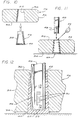
- the improved tool handle 10 comprises, generally, a tapered slug or shaft retainer 22 which is configured for insertion into an eyehole 24 of a tool head 26, which receives and is bonded to a high strength handle shaft 28.
- a grip 30 is preferably molded onto a lower end of the handle shaft 28 to ensheathe the handle shaft and to position an upper end of the grip adjacent to a lower portion of the tool head 26.
- Tool heads which may be advantageously utilized in connection with the improved tool handle 10 of the present invention comprise most of the broad range of percussive-type tool heads.
- Such tool heads typically include a body portion 32 and either a single-taper or double-tapered eyehole 24. In both instances, the eyehole 24 has a tapered portion which expands toward a top 34 of the tool head 26.
- the handle of the tool typically extends downwardly and away from a lower or bottom portion 36 of the tool head 26.
- the shaft retainer 22 comprises a generally frusto-conical slug which is dimensioned for at least partial insertion into the eyehole 24 of the tool head 26.
- the shaft retainer 22 is molded of a glass-reinforced nylon material for high strength and durability.
- the shaft retainer 22 includes an outer surface body portion 38, an upper enlarged portion 40 which is dimensioned so as to be incapable of passing through the eyehole 24, and an inner cavity 42 which has an opening 44 opposite to the upper enlarged portion 40.
- the inner cavity 42 is slightly tapered so as to expand towards an upper end of the cavity opposite to the opening 44. This taper is on the order of three degrees.
- the surfaces of the inner cavity 42 include keyways 46 which extend generally perpendicularly to the longitudinal axis of the shaft retainer 22. The purpose of these keyways is to provide supplemental, anchoring channels into which an adhesive may flow for purposes of bonding the shaft retainer 22 to the portion of the handle shaft 28 inserted therein.
- the high strength handle shaft 28 may be manufactured of any suitable material, including metal, but is preferably formed of a fiberglass-resin composite material.
- the handle shaft 28 is manufactured so that it has a generally uniform cross-sectional dimension taken generally perpendicular to its longitudinal axis, and is of sufficient length to extend substantially the entire intended length of the tool handle 10.
- the handle shaft 28 includes an upper end 48 configured for insertion into the inner cavity 42 of the shaft retainer 22. When the shaft retainer 22 is securely positioned within the eyehole 24, the upper end 48 of the handle shaft 28 extends substantially the length of the eyehole and downwardly from the bottom edge 36 of the tool head 26. As illustrated in FIGS.
- At least one of the outer surfaces of the upper end 48 of the handle shaft 28 includes keyways 50 which extend generally perpendicularly to the longitudinal axis of the handle shaft 28.
- the keyways 50 provide channeled anchoring slots for an adhesive 52 which is utilized to bond the upper end 48 of the handle shaft 28 within the inner cavity 42 of the shaft retainer 22.
- ribs 54 Extending longitudinally within the inner cavity 42 of the shaft retainer 22 are a plurality of ribs 54. These ribs 54 provide means within the inner cavity 42 for rigidly aligning the longitudinal axis of the handle shaft 28 with the longitudinal axis of the shaft retainer 22. The ribs 54 are dimensioned so as to frictionally engage the upper end 48 of the handle shaft 28 as it is driven into the inner cavity 42. Since the outer dimension of the handle shaft 28 may vary, depending on manufacturing tolerances, the ribs 54 are likely to be coined to some degree as the handle shaft 28 is driven into the shaft retainer 22.
- the ribs 54 also ensure sufficient space between the upper end 48 of the handle shaft 28 and the walls of the inner cavity 42 of the shaft retainer 22, to provide sufficient clearance for the adhesive 52 to flow between the two members and into the keyways 46 and 50.
- the adhesive 52 is allowed to cure, a rigid, high strength bond is formed between the shaft retainer 22 and the handle shaft 28.
- the slight taper of the inner cavity 42 acts to strengthen the bond between the shaft retainer 22 and the handle shaft 28.
- cured adhesive between the handle shaft 28 and the walls of the inner cavity 42 creates an incompressible wedge which cannot be removed under normal circumstances from the shaft retainer 22.
- the grip 30 has been previously molded directly onto the handle shaft 28, then after the handle shaft 28 is mated with the shaft retainer 22, assembly of the tool handle 10 to the tool head is complete. It may be preferable in some circumstances, however, to assemble the grip 30 to the handle shaft 28 after assembly of the handle shaft to the shaft retainer 22. If such further assembly of the grip 30 to the handle shaft 28 is necessary, the grip 30 is slid over a lower end 56 of the handle shaft 28 (FIG. 14). An upper end 58 of the grip 30 may be situated adjacent to the bottom surface 36 of the tool head 26.
- the grip may be of any suitable length, however.
- the grip 30 is preferably molded into a desirable shape from any material which is strong and yet comfortably handled by a user.
- the grip 30 itself primarily serves as a convenient surface and mass for which the user can grasp the tool handle 10. It does not provide the strength characteristics of the tool handle 10. Rather, the inherent strength of the tool handle 10 is provided by the shaft retainer 22 and the handle shaft 28.
- a ferrule may be added to the tool handle 10.
- the ferrule would typically be provided between the upper edge 58 of the grip 30 and the lower edge 36 of the tool head 26.
- the ferrule would he permitted a limited adjustable sliding range relative to the grip 30 to accommodate various tool head thicknesses.
- an adhesive 60 is placed within a cavity 62 of the grip 30 prior to its being slid over the lower end 56 of the handle shaft 28. This adhesive 60 tends to become uniformly dispersed between the inner surface of the cavity 62, and the outer surface of the handle shaft 28, and when allowed to cure, forms a strong bond between the two components.
- the securing means comprises a mechanical lock which is illustrated as a rack of unidirectional spring-steel barbs 64 fixed to at least one surface of the handle shaft 28 below the bottom edge 36 of the tool head 26.
- the barbs 64 are constructed so as to allow the grip 30 to be slid onto the handle shaft 28, but prevent removal of the grip from the handle shaft.
- the design of the barbs 62 permits the surfaces of the cavity 62 of the grip 30 to slide over the sharp edges thereof, but these same sharp edges dig into the relatively soft material of the grip 30 if the grip is pulled in an opposite direction.
- the handle shaft 28 is provided with a generally uniform cross-sectional dimension taken perpendicular its longitudinal axis.
- This cross-sectional dimension generally corresponds with the cross-sectional dimension of both the inner cavity 42 of the shaft retainer 22, and the cross-sectional dimension of the cavity 62 of the grip 30, when each is taken perpendicular to its longitudinal axis. This helps to insure that the handle shaft 28 will not be permitted to twist or turn relative to the shaft retainer 22, and further that the grip 30 will not be permitted to twist and/or turn relative to the handle shaft 28.
- the assembly of the tool handle 10 is illustrated best in FIGS. 2, 10-12, 14 and 16.
- the present invention provides a highly reliable, simplified method by which a handle can be installed onto most types of percussive tool heads, in a manner which effectively prohibits the tool head from flying off the handle unintentionally.
- the shaft retainer 22 is banged or thumped into the eyehole 24 from the top 34 of the tool head 26. Since the upper portion 40 of the shaft retainer 22 is incapable of passing through the eyehole 24, there is no danger that the tool head 26 will ever fly off the tool handle 10.
- the outer surface 38 of the shaft retainer 22 is configured to generally match the taper of the eyehole 24, there is typically a solid area of contact between the shaft retainer 22 and the body 32 of the tool head 26 within the eyehole 24. It has been found that the tool handle 20 performs satisfactorily so long as a minimum of twenty-five percent of the body 32 surrounding the eyehole 24 is in direct contact with the outer surface body portion 38 of the shaft retainer 22.
- a measured quantity of the adhesive 52 is placed within the inner cavity 42 of the shaft retainer 22. This is but a preparatory step which is done prior to driving the upper end 48 of the handle shaft 28 into the inner cavity 42.
- the adhesive 52 flows into the keyways 46 and 50, and spreads generally uniformly between the handle shaft 28 and the shaft retainer 22.
- the ribs 54 tend to align the handle shaft 28 with respect to the shaft retainer, and further to provide enough frictional force between the handle shaft 28 and the shaft retainer 22, that the lower end 56 of the handle shaft 28 can be grasped and lifted, before the adhesive 52 has been allowed to bond the handle shaft 28 to the shaft retainer 22, without any separation of those two components. This is often desirable in a manufacturing operation.
- the grip 30 will have been previously molded directly onto the handle shaft 28 (FIG. 1). In this case, after the adhesive 52 has been allowed to cure, assembly of the tool handle 10 to the tool head 26 is complete. However, it is sometimes preferable to ensheathe a lower portion of the handle shaft 28 with a grip 30 of a selected length after the upper end 48 of the handle shaft 28 is bonded within the inner cavity 42 of the shaft retainer 22. Two methods are illustrated in the accompanying drawings for attaching the grip 30 to the handle shaft 28. In a first of these embodiments, an adhesive 60 is placed within the cavity 62 of the grip 30 in much the same manner as the adhesive 52 is placed within the inner cavity 42 of the shaft retainer 22.
- the adhesive 60 becomes generally uniformly dispersed between the walls of the cavity 62 and the handle shaft 28. Once this adhesive 60 has been allowed to cure, the handling of the tool is complete, and the completed tool handle 10 may be used for all intended purposes.
- a rack of barbs 64 is attached by any suitable means to the handle shaft 28, and then the grip is simply slid over the barbs 64 to abut against the tool head 26.
- the barbs 64 prevent removal of the grip 30 in much the same manner as the adhesive 60 does.
- the present invention provides a highly reliable, simplified method by which a handle can be installed onto a percussive tool head, which effectively prohibits the tool head from flying off the handle unintentionally.
- the tool handle 10 of the present invention includes a minimum number of separate parts which greatly simplifies assembly of the handle to the tool head 26.
- the grip 30 may be molded so that it will comfortably fit a user's hands.
- the tool handle 10 of the present invention facilitates use of reinforced composite tool handles as field replacements for older tools, and the present method overcomes drawbacks associated with fixing such handles within the eyehole of the tool head solely by means of an epoxy.
Landscapes
- Mechanical Engineering (AREA)
- Engineering & Computer Science (AREA)
- Details Of Spanners, Wrenches, And Screw Drivers And Accessories (AREA)
- Portable Nailing Machines And Staplers (AREA)
- Surgical Instruments (AREA)
- Control Of Transmission Device (AREA)
- Electroluminescent Light Sources (AREA)
- Road Paving Structures (AREA)
- Adhesives Or Adhesive Processes (AREA)
- Walking Sticks, Umbrellas, And Fans (AREA)
- Lining Or Joining Of Plastics Or The Like (AREA)
- Finish Polishing, Edge Sharpening, And Grinding By Specific Grinding Devices (AREA)
- Golf Clubs (AREA)
- Food-Manufacturing Devices (AREA)
Claims (9)
- Handbetätigtes Werkzeug, umfassend:einen Werkzeugkopf (26) mit einem Grundkörper (32) und einem sich durch den Grundkörper erstreckenden Ösenloch (24), wobei das Ösenloch eine Verjüngung aufweist, die sich in Richtung des oberen Endes (34) des Werkzeugkopfs (26) erweitert;ein Schafthalteteil (22), das zum teilweisen Einsetzen in den Werkzeugkopf durch das Ösenloch (24) von dessen oberem Ende (34) her bemessen ist, wobei das Schafthalteteil (22) ein sich verjüngendes, im allgemeinen kegelstumpfförmiges Rohrstück bildet, dessen äußerer Oberflächenbereich (38) im allgemeinen einem Abschnitt des Ösenlochs benachbart zur Oberseite des Werkzeugkopfs (26) entspricht, mit einem oberen verbreiterten Abschnitt (40), der nicht durch das Ösenloch hindurchgehen kann, und mit einem inneren Hohlraum (42), der eine Öffnung (44) gegenüber dem oberen verbreiterten Abschnitt (40) aufweist; undeinen hochfesten Stielschaft (28) mit einem oberen Endabschnitt (48), der innerhalb des inneren Hohlraums des Schafthalteteils (22) befestigt ist; dadurch gekennzeichnet, daßdas Schafthalteteil (22) innerhalb des inneren Hohlraums (42) des Schafthalteteils (22) mit dem oberen Endabschnitt (48) des Schafts (52) mittels eines Verbundklebstoffs (52) verbunden ist, der zwischen den oberen Endabschnitt (48) des Schafts und den inneren Hohlraum (42) des Schafthalteteils (22) eingefügt ist, wobei ein Griffstück (30) vorhanden ist, dessen oberer Endabschnitt (58) benachbart zu einem Teil des Werkzeugkopfs (26) liegt und wobei das Griffstück fest an dem Stielschaft (28) gehalten ist.
- Handbetätigtes Werkzeug nach Anspruch 1, dadurch gekennzeichnet, daß das Schafthalteteil (22) eine Anzahl verformbarer Längsrippen (54) aufweist, die in den inneren Hohlraum (42) vorstehen, um die Längsachse des Stielschafts (28) starr mit der Längsachse des Schafthalteteils auszurichten und um den Stielschaft durch Reibschluß zu erfassen, ohne sich in diesen einzulagern, wenn der Stielschaft in den inneren Hohlraum eingesetzt wird.
- Handbetätigtes Werkzeug, umfassend:einen Werkzeugkopf (26) mit einem Grundkörper (32) und einem sich durch den Grundkörper erstreckenden Ösenloch (24), wobei das Ösenloch eine Verjüngung aufweist, die sich in Richtung des oberen Endes (34) des Werkzeugkopfs (26) erweitert;ein Schafthalteteil (22), das zum teilweisen Einsetzen in den Werkzeugkopf durch das Ösenloch (24) von dessen oberem Ende (34) her bemessen ist, wobei das Schafthalteteil (22) ein sich verjüngendes, im allgemeinen kegelstumpfförmiges Rohrstück bildet, dessen äußerer Oberflächenbereich (38) im allgemeinen einem Abschnitt des Ösenlochs benachbart zur Oberseite des Werkzeugkopfs (26) entspricht, mit einem oberen verbreiterten Abschnitt (40), der nicht durch das Ösenloch hindurchgehen kann, und mit einem inneren Hohlraum (42), der eine Öffnung (44) gegenüber dem oberen verbreiterten Abschnitt (40) aufweist; undeinen hochfesten Stielschaft (28) mit einem oberen Endabschnitt (48), der innerhalb des inneren Hohlraums des Schafthalteteils (22) befestigt ist; dadurch gekennzeichnet, daßdas Schafthalteteil (22) innerhalb des inneren Hohlraums (42) des Schafthalteteils (22) mit dem oberen Endabschnitt (48) des Schafts (52) mittels eines Verbundklebstoffs (52) verbunden ist, der zwischen den oberen Endabschnitt (48) des Schafts und den inneren Hohlraum (42) des Schafthalteteils (22) eingefügt ist, wobei das Schafthalteteil (22) eine Anzahl verformbarer Längsrippen (54) aufweist, die in den inneren Hohlraum (42) vorstehen, um die Längsachse des Stielschafts (28) starr mit der Längsachse des Schafthalteteils auszurichten und um den Stielschaft durch Reibschluß zu erfassen, ohne sich in diesen einzulagern, wenn der Stielschaft in den inneren Hohlraum eingesetzt wird.
- Handbetätigtes Werkzeug nach Anspruch 1 oder 3, dadurch gekennzeichnet, daß die Oberflächen des inneren Hohlraums (42) des Schafthalteteils (22) Keilnuten (46) aufweisen, die sich im allgemeinen senkrecht zur Längsachse des Schafthalteteils erstrecken.
- Handbetätigtes Werkzeug nach einem der vorangehenden Ansprüche, dadurch gekennzeichnet, daß wenigstens eine der Oberflächen des oberen Endabschnitts des Stielschafts (28) Keilnuten (50) aufweist, die sich im allgemeinen senkrecht zur Längsachse des Stielschafts erstrecken.
- Handbetätigtes Werkzeug nach einem der vorangehenden Ansprüche, dadurch gekennzeichnet, daß der Stielschaft (28) senkrecht zu seiner Längsachse eine im allgemeinen gleichförmige Querschnittsabmessung aufweist, wobei diese Querschnittsabmessung im allgemeinen der Querschnittsabmessung des inneren Hohlraums (42) senkrecht zur Längsachse des Schafthalteteils (22) entspricht.
- Handbetätigtes Werkzeug nach einem der Ansprüche 1 oder 2, gekennzeichnet durch einen Verbundklebstoff (60), der zwischen das Griffstück (30) und das Schafthalteteil (28) eingefügt ist, um das Griffstück sicher am Stielschaft zu befestigen.
- Handbetätigtes Werkzeug nach Anspruch 1 oder 2, gekennzeichnet durch Widerhaken (64) zum sicheren Befestigen des Griffstücks am Stielschaft.
- Handbetätigtes Werkzeug nach Anspruch 1 oder 2, dadurch gekennzeichnet, daß das Griffstück (30) unmittelbar auf den Stielschaft (28) aufgeformt ist.
Applications Claiming Priority (3)
| Application Number | Priority Date | Filing Date | Title |
|---|---|---|---|
| US07/486,440 US5031272A (en) | 1990-02-28 | 1990-02-28 | Tool handle and method of attaching a handle to a percussive tool head |
| US486440 | 1990-02-28 | ||
| PCT/US1990/006117 WO1991012749A1 (en) | 1990-02-28 | 1990-10-23 | Tool handle and method of attaching a handle to a percussive tool head |
Publications (3)
| Publication Number | Publication Date |
|---|---|
| EP0517709A1 EP0517709A1 (de) | 1992-12-16 |
| EP0517709A4 EP0517709A4 (en) | 1993-04-07 |
| EP0517709B1 true EP0517709B1 (de) | 1996-12-18 |
Family
ID=23931892
Family Applications (1)
| Application Number | Title | Priority Date | Filing Date |
|---|---|---|---|
| EP91902903A Expired - Lifetime EP0517709B1 (de) | 1990-02-28 | 1990-10-23 | Werkzeuggriff und verfahren zum befestigen eines griffs an einen schlagwerkzeugkopf |
Country Status (8)
| Country | Link |
|---|---|
| US (1) | US5031272A (de) |
| EP (1) | EP0517709B1 (de) |
| AT (1) | ATE146341T1 (de) |
| AU (1) | AU634861B2 (de) |
| DE (1) | DE69029475T2 (de) |
| FI (1) | FI921020A0 (de) |
| NO (1) | NO177988C (de) |
| WO (1) | WO1991012749A1 (de) |
Families Citing this family (25)
| Publication number | Priority date | Publication date | Assignee | Title |
|---|---|---|---|---|
| JPH0430345U (de) * | 1990-07-05 | 1992-03-11 | ||
| GB2253455B (en) * | 1991-02-20 | 1994-08-31 | Michael Patrick Walsh | The joining of first and second members at least one of which is a fibreglass member |
| US5588343A (en) * | 1994-09-15 | 1996-12-31 | The Stanley Works | Handle with improved grip assembly for hammers and the like and method of making same |
| US5651631A (en) * | 1996-07-10 | 1997-07-29 | Carmien; Joseph Allen | Method and apparatus for attaching a tool handle to a tool head |
| US5804012A (en) * | 1997-01-21 | 1998-09-08 | Carmien; Joseph Allen | Process for manufacturing a filament wound, localized strength tool handle |
| US5996442A (en) * | 1997-08-05 | 1999-12-07 | Carmien; Joseph Allen | Hand tool having interchangeable and replaceable striking heads, and assembly process |
| US6227075B1 (en) | 1999-01-25 | 2001-05-08 | Joseph Allen Carmien | Nonrecoil hammer |
| JP2001162545A (ja) | 1999-09-07 | 2001-06-19 | Snap-On Tools Corp | ラチェット式手工具 |
| US6729877B2 (en) * | 2001-07-30 | 2004-05-04 | Hu-Friedy Mfg. Co., Inc. | Dental instrument having enlarged handle and glued cone |
| USD490679S1 (en) | 2003-05-13 | 2004-06-01 | Yi-Kung Hung | Mallet |
| FR2873053B1 (fr) * | 2004-07-19 | 2008-01-04 | Leborgne Sa | Dispositif de montage et de fixation d'un manche a un outil de frappe |
| US20060035041A1 (en) * | 2004-08-10 | 2006-02-16 | Materials Sciences Corporation | Fastening apparatus and method |
| US7168338B2 (en) * | 2004-11-29 | 2007-01-30 | Snap-On Incorporated | Dead blow hammer with composite holder |
| CA2506986A1 (en) * | 2005-05-10 | 2006-11-10 | Garant Gp | A shaft for tools, and tool and a method of fabrication thereof |
| US20100139458A1 (en) * | 2008-12-09 | 2010-06-10 | Ames True Temper, Inc. | Coupling for handle and tool head |
| USD606806S1 (en) | 2009-08-26 | 2009-12-29 | Le Creuset Sas | Utensil handle |
| US8235435B2 (en) | 2009-08-26 | 2012-08-07 | Le Creuset Sas | Utensil handle |
| CN102235326B (zh) * | 2010-04-30 | 2013-12-25 | 住友重机械工业株式会社 | 动力传递装置及动力传递装置的联轴器单元 |
| USD689345S1 (en) | 2011-10-10 | 2013-09-10 | Le Creuset Sas | Sauté spoon |
| USD677129S1 (en) | 2011-10-10 | 2013-03-05 | Le Creuset Sas | Sauté spoon |
| US8752224B2 (en) | 2012-02-06 | 2014-06-17 | Nupla Corporation | Composite pry bar and striking tool |
| EP3814499A2 (de) | 2018-06-28 | 2021-05-05 | CRISPR Therapeutics AG | Zusammensetzungen und verfahren zur genomeditierung durch insertion von donorpolynukleotiden |
| EP3966327A1 (de) | 2019-05-08 | 2022-03-16 | Vertex Pharmaceuticals Incorporated | Crispr/cas all-in-two-vektorsystemen zur behandlung von dmd |
| US20210008161A1 (en) | 2019-06-17 | 2021-01-14 | Crispr Therapeutics Ag | Methods and compositions for improved homology directed repair |
| US12472617B2 (en) * | 2021-11-15 | 2025-11-18 | Js Products, Inc. | Vibration damper for hand-operated striking tools |
Family Cites Families (30)
| Publication number | Priority date | Publication date | Assignee | Title |
|---|---|---|---|---|
| US404663A (en) * | 1889-06-04 | Device for securing tools to handles | ||
| US894155A (en) * | 1907-05-04 | 1908-07-21 | Cary W Layton | Tool-handle. |
| US1435851A (en) * | 1920-04-14 | 1922-11-14 | Isham Harry Stevens | Rubberset cushioned implement handle and insert thimble |
| US1409142A (en) * | 1920-08-03 | 1922-03-07 | Mecky Company A | Handle-bar grip |
| US2205769A (en) * | 1937-06-28 | 1940-06-25 | Ernest J Sweetland | Implement handle |
| US2850331A (en) * | 1954-09-13 | 1958-09-02 | Fayette R Plumb Inc | Handle connection for percussive tool |
| US2837381A (en) * | 1955-11-21 | 1958-06-03 | Oscar L Sarlandt | Reinforced tool handle attachment |
| US3090653A (en) * | 1959-07-02 | 1963-05-21 | True Temper Corp | Hand tools |
| CH417504A (de) * | 1962-10-20 | 1966-07-15 | Schwartz & Co G | Hammer |
| DE1800559A1 (de) * | 1968-10-02 | 1970-06-11 | Emil Schulte | Keillose Verbindung zwischen Stiel und Werkzeug mit Absicherung |
| US3819288A (en) * | 1972-01-28 | 1974-06-25 | Nupla Corp | Adapter for fiberglass tool handles and other fiberglass connections |
| US3753602A (en) * | 1972-01-28 | 1973-08-21 | Nupla Corp | Adapter for fiberglass tool handles and other fiberglass connections |
| US3877826A (en) * | 1973-03-12 | 1975-04-15 | Stanley Works | Handle connection for impact tools |
| US3915782A (en) * | 1973-03-12 | 1975-10-28 | Nupla Corp | Method of attaching hand grips to fiberglass tool handles |
| DE2342982A1 (de) * | 1973-08-25 | 1975-03-06 | Peddinghaus Carl Dan Kg | Handgriff fuer stielhandwerkzeuge |
| US3874433A (en) * | 1973-09-12 | 1975-04-01 | Stanley Works | Hand tool connection and trim collar therefor |
| US3917421A (en) * | 1974-05-28 | 1975-11-04 | Nupla Corp | Insert for attaching fiberglass tool handles |
| US4085784A (en) * | 1975-06-26 | 1978-04-25 | Fish Herbert L | Impact tool and handle assembly therefor |
| US4030847A (en) * | 1976-06-10 | 1977-06-21 | Nupla Corporation | Adapter for fiberglass tool handles and other fiberglass connections |
| US4139930A (en) * | 1977-10-11 | 1979-02-20 | Cox Charles T | All-metal hammer handle adapter construction |
| US4165771A (en) * | 1978-04-24 | 1979-08-28 | True Temper Corporation | Impact tool having a pre-formed fiberglass handle |
| ZA784458B (en) * | 1978-08-07 | 1979-12-27 | Modern Inventions Ltd | Handle |
| US4287640A (en) * | 1979-08-17 | 1981-09-08 | Ixl Manufacturing Co., Inc. | Tool handle and method of making same |
| US4367969A (en) * | 1979-08-31 | 1983-01-11 | Carmien Joseph A | Bushing for attaching fiberglass tool handles |
| US4286640A (en) * | 1980-01-21 | 1981-09-01 | Abbott Laboratories | Tamperproof port cover |
| US4291998A (en) * | 1980-06-05 | 1981-09-29 | The Budd Company | Replacement handle for a tool |
| FR2495986B1 (fr) * | 1980-12-12 | 1986-08-29 | Loire Et Milourd Moulin Blanc | Manche pour marteaux et autres outils a oeil |
| US4558726A (en) * | 1981-04-27 | 1985-12-17 | Clay Howard W | Hammer with replaceable head |
| GB8531885D0 (en) * | 1985-12-30 | 1986-02-05 | Fox J K Snr | Tool |
| FR2612442B1 (fr) * | 1987-03-19 | 1989-10-13 | Edme Lacroix Sa | Douille de raccordement d'un manche cylindrique ou ovale a l'oeil conique d'un outil |
-
1990
- 1990-02-28 US US07/486,440 patent/US5031272A/en not_active Expired - Lifetime
- 1990-10-23 AT AT91902903T patent/ATE146341T1/de not_active IP Right Cessation
- 1990-10-23 FI FI921020A patent/FI921020A0/fi not_active Application Discontinuation
- 1990-10-23 WO PCT/US1990/006117 patent/WO1991012749A1/en not_active Ceased
- 1990-10-23 AU AU71466/91A patent/AU634861B2/en not_active Ceased
- 1990-10-23 DE DE69029475T patent/DE69029475T2/de not_active Expired - Fee Related
- 1990-10-23 EP EP91902903A patent/EP0517709B1/de not_active Expired - Lifetime
-
1992
- 1992-08-27 NO NO923362A patent/NO177988C/no unknown
Also Published As
| Publication number | Publication date |
|---|---|
| FI921020A7 (fi) | 1992-03-09 |
| AU7146691A (en) | 1991-09-18 |
| FI921020A0 (fi) | 1992-03-09 |
| US5031272A (en) | 1991-07-16 |
| DE69029475T2 (de) | 1997-04-03 |
| AU634861B2 (en) | 1993-03-04 |
| NO177988B (no) | 1995-09-25 |
| DE69029475D1 (de) | 1997-01-30 |
| EP0517709A4 (en) | 1993-04-07 |
| NO923362L (no) | 1992-08-27 |
| WO1991012749A1 (en) | 1991-09-05 |
| ATE146341T1 (de) | 1997-01-15 |
| NO177988C (no) | 1996-01-03 |
| NO923362D0 (no) | 1992-08-27 |
| EP0517709A1 (de) | 1992-12-16 |
Similar Documents
| Publication | Publication Date | Title |
|---|---|---|
| US5031272A (en) | Tool handle and method of attaching a handle to a percussive tool head | |
| US5056381A (en) | Replacement tool handle, hand tool and method | |
| US5651631A (en) | Method and apparatus for attaching a tool handle to a tool head | |
| CA1260310A (en) | Tool handle | |
| US5375486A (en) | Surface protective striking tools | |
| US5528834A (en) | Fixed-blade knife for rugged service and its manufacture | |
| US4418732A (en) | Hand tool and a core reinforced molded synthetic material handle therefor | |
| US7168338B2 (en) | Dead blow hammer with composite holder | |
| CN101992462B (zh) | 工具手柄及其制造方法 | |
| US5996442A (en) | Hand tool having interchangeable and replaceable striking heads, and assembly process | |
| US5123303A (en) | Impact tool, handle assembly and method of attaching handle to head | |
| CA2191060A1 (en) | Plastic molded float handle | |
| US4085784A (en) | Impact tool and handle assembly therefor | |
| US5896788A (en) | Hammer with improved handle interlock and method of making same | |
| US3819288A (en) | Adapter for fiberglass tool handles and other fiberglass connections | |
| US4165771A (en) | Impact tool having a pre-formed fiberglass handle | |
| US4188703A (en) | Impact tool, handle assembly therefor, and method of attaching handle to head | |
| CA2038820C (en) | Tool handle and method of attaching a handle to a percussive tool head | |
| CA2046421C (en) | Replacement tool handle | |
| US5643520A (en) | Process for manufacturing a bow rake | |
| US3602277A (en) | Handtools | |
| CN201559185U (zh) | 工具手柄 | |
| CA2687993C (en) | Coupling for handle and tool head | |
| EP1782926A2 (de) | Werkzeug mit Arbeitskopf und Griff sowie sein Zusammenbauverfahren | |
| KR102695230B1 (ko) | 파이프 자루형 낫 고정구 |
Legal Events
| Date | Code | Title | Description |
|---|---|---|---|
| PUAI | Public reference made under article 153(3) epc to a published international application that has entered the european phase |
Free format text: ORIGINAL CODE: 0009012 |
|
| 17P | Request for examination filed |
Effective date: 19911213 |
|
| AK | Designated contracting states |
Kind code of ref document: A1 Designated state(s): AT BE CH DE DK ES FR GB GR IT LI LU NL SE |
|
| A4 | Supplementary search report drawn up and despatched |
Effective date: 19930222 |
|
| AK | Designated contracting states |
Kind code of ref document: A4 Designated state(s): AT BE CH DE DK ES FR GB GR IT LI LU NL SE |
|
| 17Q | First examination report despatched |
Effective date: 19940719 |
|
| GRAH | Despatch of communication of intention to grant a patent |
Free format text: ORIGINAL CODE: EPIDOS IGRA |
|
| GRAH | Despatch of communication of intention to grant a patent |
Free format text: ORIGINAL CODE: EPIDOS IGRA |
|
| GRAA | (expected) grant |
Free format text: ORIGINAL CODE: 0009210 |
|
| AK | Designated contracting states |
Kind code of ref document: B1 Designated state(s): AT BE CH DE DK ES FR GB GR IT LI LU NL SE |
|
| PG25 | Lapsed in a contracting state [announced via postgrant information from national office to epo] |
Ref country code: IT Free format text: LAPSE BECAUSE OF FAILURE TO SUBMIT A TRANSLATION OF THE DESCRIPTION OR TO PAY THE FEE WITHIN THE PRESCRIBED TIME-LIMIT;WARNING: LAPSES OF ITALIAN PATENTS WITH EFFECTIVE DATE BEFORE 2007 MAY HAVE OCCURRED AT ANY TIME BEFORE 2007. THE CORRECT EFFECTIVE DATE MAY BE DIFFERENT FROM THE ONE RECORDED. Effective date: 19961218 Ref country code: GR Free format text: LAPSE BECAUSE OF FAILURE TO SUBMIT A TRANSLATION OF THE DESCRIPTION OR TO PAY THE FEE WITHIN THE PRESCRIBED TIME-LIMIT Effective date: 19961218 Ref country code: CH Effective date: 19961218 Ref country code: DK Effective date: 19961218 Ref country code: ES Free format text: THE PATENT HAS BEEN ANNULLED BY A DECISION OF A NATIONAL AUTHORITY Effective date: 19961218 Ref country code: AT Effective date: 19961218 Ref country code: NL Free format text: LAPSE BECAUSE OF FAILURE TO SUBMIT A TRANSLATION OF THE DESCRIPTION OR TO PAY THE FEE WITHIN THE PRESCRIBED TIME-LIMIT Effective date: 19961218 Ref country code: LI Effective date: 19961218 |
|
| REF | Corresponds to: |
Ref document number: 146341 Country of ref document: AT Date of ref document: 19970115 Kind code of ref document: T |
|
| REF | Corresponds to: |
Ref document number: 69029475 Country of ref document: DE Date of ref document: 19970130 |
|
| ET | Fr: translation filed | ||
| PG25 | Lapsed in a contracting state [announced via postgrant information from national office to epo] |
Ref country code: SE Effective date: 19970318 |
|
| NLV1 | Nl: lapsed or annulled due to failure to fulfill the requirements of art. 29p and 29m of the patents act | ||
| REG | Reference to a national code |
Ref country code: CH Ref legal event code: PL |
|
| PG25 | Lapsed in a contracting state [announced via postgrant information from national office to epo] |
Ref country code: GB Free format text: LAPSE BECAUSE OF NON-PAYMENT OF DUE FEES Effective date: 19971023 |
|
| PLBE | No opposition filed within time limit |
Free format text: ORIGINAL CODE: 0009261 |
|
| 26N | No opposition filed | ||
| GBPC | Gb: european patent ceased through non-payment of renewal fee |
Effective date: 19971023 |
|
| PG25 | Lapsed in a contracting state [announced via postgrant information from national office to epo] |
Ref country code: DE Free format text: LAPSE BECAUSE OF NON-PAYMENT OF DUE FEES Effective date: 19980701 |
|
| PGFP | Annual fee paid to national office [announced via postgrant information from national office to epo] |
Ref country code: FR Payment date: 19981009 Year of fee payment: 9 |
|
| PGFP | Annual fee paid to national office [announced via postgrant information from national office to epo] |
Ref country code: LU Payment date: 19981020 Year of fee payment: 9 |
|
| PGFP | Annual fee paid to national office [announced via postgrant information from national office to epo] |
Ref country code: BE Payment date: 19981216 Year of fee payment: 9 |
|
| PG25 | Lapsed in a contracting state [announced via postgrant information from national office to epo] |
Ref country code: LU Free format text: LAPSE BECAUSE OF NON-PAYMENT OF DUE FEES Effective date: 19991023 |
|
| PG25 | Lapsed in a contracting state [announced via postgrant information from national office to epo] |
Ref country code: BE Free format text: LAPSE BECAUSE OF NON-PAYMENT OF DUE FEES Effective date: 19991031 |
|
| BERE | Be: lapsed |
Owner name: CARMIEN JOSEPH ALLEN Effective date: 19991031 |
|
| PG25 | Lapsed in a contracting state [announced via postgrant information from national office to epo] |
Ref country code: FR Free format text: LAPSE BECAUSE OF NON-PAYMENT OF DUE FEES Effective date: 20000630 |
|
| REG | Reference to a national code |
Ref country code: FR Ref legal event code: ST |