EP0515832B1 - Machine to cut off pieces of a tube - Google Patents
Machine to cut off pieces of a tube Download PDFInfo
- Publication number
- EP0515832B1 EP0515832B1 EP92106841A EP92106841A EP0515832B1 EP 0515832 B1 EP0515832 B1 EP 0515832B1 EP 92106841 A EP92106841 A EP 92106841A EP 92106841 A EP92106841 A EP 92106841A EP 0515832 B1 EP0515832 B1 EP 0515832B1
- Authority
- EP
- European Patent Office
- Prior art keywords
- face plate
- machine according
- thrust
- cut
- steel
- Prior art date
- Legal status (The legal status is an assumption and is not a legal conclusion. Google has not performed a legal analysis and makes no representation as to the accuracy of the status listed.)
- Expired - Lifetime
Links
Images


Classifications
-
- B—PERFORMING OPERATIONS; TRANSPORTING
- B23—MACHINE TOOLS; METAL-WORKING NOT OTHERWISE PROVIDED FOR
- B23B—TURNING; BORING
- B23B5/00—Turning-machines or devices specially adapted for particular work; Accessories specially adapted therefor
- B23B5/16—Turning-machines or devices specially adapted for particular work; Accessories specially adapted therefor for bevelling, chamfering, or deburring the ends of bars or tubes
- B23B5/161—Devices attached to the workpiece
- B23B5/163—Devices attached to the workpiece with an external clamping device
-
- B—PERFORMING OPERATIONS; TRANSPORTING
- B23—MACHINE TOOLS; METAL-WORKING NOT OTHERWISE PROVIDED FOR
- B23D—PLANING; SLOTTING; SHEARING; BROACHING; SAWING; FILING; SCRAPING; LIKE OPERATIONS FOR WORKING METAL BY REMOVING MATERIAL, NOT OTHERWISE PROVIDED FOR
- B23D21/00—Machines or devices for shearing or cutting tubes
- B23D21/04—Tube-severing machines with rotating tool-carrier
Definitions
- the present invention relates to a machine for parting pipe sections from a pipe and is based on a machine in which the pipe workpiece is held in at least two clamping devices located on both sides of the interface and the one rotating on the section between the fixing points of the pipe in Has a fixed face plate in the axial direction which carries tool steels which can be advanced in the radial direction for parting off and chamfering the outer and inner cutting edges, the clamping device fixing the pipe section to be cut off being movable in the axial direction.
- the object of the present invention is to provide a machine for parting off pipe sections from a pipe, with which, following the parting off, the chamfering of the outer and inner edges of the cut surfaces can be carried out quickly and easily. Above all, it should be unnecessary to push the supply pipe workpiece axially back to bring the handle to the inner edge of the cut surface and then to push it back again to effect the internal chamfering.
- this object is achieved in that at least one of the tools which effect the internal chamfering can be driven in the axial direction in relation to the face plate independently of the radial feed.
- a machine for cutting pipes to length is known from US Pat. No. 4,430,913, in which a tool steel running around a face plate, namely a deburring knife, performs both a radial and an axial feed movement.
- a tool steel running around a face plate namely a deburring knife
- this is not about parting off pipe sections in which brackets must be provided on both sides of the interface, but only about dressing a pipe end, only one ring-shaped piece of waste arises, which neither has to be held nor subsequently beveled.
- the movement of the deburring knife in the axial direction is not a driven and therefore independently controllable movement, but an auxiliary movement derived from the radially inward movement, which only produces the position of the deburring knife that is required in the subsequent deburring process for the radially outward movement.
- a separate drive in the axial direction is not provided. There is only a switching back and forth of the deburring knife derived from the radial displacements, which does not effect internal chamfering and could not at all.
- a support tube 3 is rigidly installed at the rear end thereof, which projects forward through the housing and in which a clamping device 5 for the tube workpiece 7, namely its stock length 7a, is arranged.
- the section 7b of the pipe workpiece 7 to be cut off is held in a clamping device 9 which is only indicated schematically.
- the clamping device 5 consists of a pressure tube 12, at the rear end of which a piston 14 is arranged, which can be acted upon by pressurizing a cylinder space 16 worked out in the rear end of the support tube 3.
- a cylinder space 16 worked out in the rear end of the support tube 3.
- its inner surface is flared and cooperates with the jaws 18 of a collet 20 in such a way that when the pressure tube 12 is advanced, the jaws 18 close tightly around the tube workpiece 7.
- a drive bushing 23 is rotatably and coaxially mounted on the support tube 3 and is supported thereon by means of roller bearings 25, 26.
- the rear drive end 28 of the drive bush 23 is designed to engage a rotary drive, not shown; in the example under consideration by means of an external toothing with which the gear of a drive motor can mesh.
- An embodiment is also possible in such a way that the drive end 28 is wrapped in a chain or a belt of a drive motor.
- a face plate 30 is fastened to the front end of the drive bushing 23 and face slides 32, 34 are located opposite it in radial guides on its front end face are slidably arranged.
- the flat slide 32 carries a parting tool 38 as a tool.
- a steel holder carrier 42 is pivotably articulated about an axis 40, which in turn carries a steel holder 44 with a handle steel 46 attached to its end as a tool.
- the handle 46 has four cutting edges, two of which are inclined at an angle to the transverse plane perpendicular to the machine axis and run symmetrically to the latter.
- the drive bushing 23 is supported by a support bearing 50 which is installed in the front wall of the housing 1 and whose inner ring encloses a support ring 52 which is seated on the drive bushing 23 and rotates with it.
- the radial feed of the parting tool 38 is brought about by the kinematic chain shown in the lower half of FIG. 1, to which a drive motor 54 for the parting tool feed belongs, which drives a threaded spindle 56, which with a nut 58 which is in a sliding outer ring 60 installed, cooperates.
- a ball screw screw drive is expediently used to achieve minimal friction.
- a sliding transmission bearing 62 is seated in the sliding outer ring 60, the inner ring of which surrounds a sliding inner ring 64 rotating with the drive bush 23 and displaceable in the axial direction on the latter.
- the displacement outer bearing 60 and the displacement inner ring 64 are rotatably and axially immovably connected to one another by the displacement transmission bearing 62, and rotation of the threaded spindle 56 in this way brings about an axial displacement of the displacement inner ring 64 rotating with the drive bushing 23.
- a push rod 66 is screwed, which projects forward through a bore of the support ring 52 to the face plate 30 and at the front end of which a tab 68 is articulated, the other end of which articulates against a deflection segment 70 which engages the face plate 30 is pivotable about an axis 72.
- the other end of the deflection segment 70 is connected in an articulated manner to the plane slide 32 via a further link 74, so that an axial displacement of the push rod 66 in the aforementioned way is converted into a radial advance of the plane slide 32 and thus the parting steel 38.
- FIG. 5 shows a variant for the implementation of this movement.
- a toothed segment 71 that can be pivoted about the axis 72 is used, which has a front rack section of the push rod 66 ′ and a rack attachment that runs at right angles to it 73 of the slide valve 32 'combs.
- the axial movement of the push rod 66 ' is also converted here into a radial feed movement of the face slide 32' on the face plate 30 '.
- a drive motor 76 for the radial feed of the handle steel drives a threaded spindle 77 on which a nut 78 is seated, which is installed in a sliding outer ring 79. Between this and a sliding inner ring 81 sits a rotationally and axially non-displaceably connecting displacement transmission bearing 80.
- a diametrically opposite threaded spindle which is synchronized with the threaded spindle 77 and which acts on a nut diametrically opposite in the sliding outer ring 79.
- bores for the passage of the threaded spindle 56 and the other threaded spindle of the cut-off steel feed kinematics lying opposite it are provided in the sliding outer ring 79 at two opposite points.
- a push rod 82 designed as a tube is screwed into the sliding inner ring 81, the front end of which is connected to a deflecting segment via at least one tab, the other end of which engages the face slide 34 by means of a further tab.
- This movement conversion corresponds to that described for the parting-off steel feed, which is why the corresponding parts involved here are no longer provided with their own reference numerals.
- An axial displacement of the push tube 82 is translated in the manner considered into a radial feed of the face slide 34 and thus of the handle 46.
- a third shift kinematics of the type under consideration causes the pivoting of the steel holder support 42 about the axis 40 on the face slide 34 and thus a movement of the handle steel 46 which runs essentially in the axial direction.
- a drive motor 86 (FIG. 3) drives a threaded spindle 87, which cooperates with a nut 88 in a sliding outer ring 89, which is rotatably and axially immovably connected to a sliding inner ring 91 by means of a sliding transmission bearing 90.
- a threaded spindle 87 which cooperates with a nut 88 in a sliding outer ring 89, which is rotatably and axially immovably connected to a sliding inner ring 91 by means of a sliding transmission bearing 90.
- the sliding outer ring 89 there are two opposite bores for the passage of the threaded spindle 77 and the paired threaded spindle belonging to it, as well as the threaded spindle 56 and the paired threaded spindle belonging to this.
- a push rod 92 is screwed, which runs forward through the push tube 82 and ends in a head 93 which cooperates with the steel holder carrier 42 by means of a sliding guide in such a way that it does not prevent movements of the same in the radial direction, movements in the axial direction however transmits and thereby generates pivoting movements of the steel holder support 42 about the axis 40.
- axially extending guide rods 95 are installed between the end walls of the housing 1, which engage through corresponding bores in the sliding outer rings 60, 79, 89 provided with sliding bushes.
- FIG. 6 shows a spreadable handle steel holder 100, which essentially consists of two pivotable arms 102, 103, each of which has a handle steel 105, 106 attached to its inwardly facing ends.
- the left arm 102 in the drawing is pivotable about a radially inner axis 110 and the right arm 103 about a radially outer axis 112 by a small angular amount.
- a pull rod 108 extends through both arms, the left end of which is fastened to a frame-fixed element and the right end of which is a head which lies in a recess in the right arm 103, between the floor this recess and the head a plate spring assembly 116 is used, which acts on the right arm 103 in the sense of a clockwise rotation about the axis 112.
- a ball insert 114 is screwed into the right arm 103, the ball of which is in contact with the arm 102 in a pressure-transmitting manner.
- the push rod 92 acts on the radially outer end of the left arm 102.
- the right arm 103 is acted upon by the action of the spring assembly 116 in the sense of a clockwise rotation about the axis 112 and presses with its ball insert 114 on the opposite location of the left arm 102, so that it is acted upon counterclockwise about its axis 110.
- the arms are swung together and both Handle steels 105, 106 are close together.
- the push rod 92 presses on the radially outer end of the left arm 102 and thereby swivels it clockwise about its axis 110. This pivoting pushes back the ball insert 114 and thereby the right arm 103 counterclockwise about it Axis 112 swiveled. Both arms move into the spread position shown in FIG. 6b, in which the handle steels 105, 106 are at a distance from one another.
- the section 7b to be cut off is cut off from the stock length 7a by the radially inward feed of the cut-off steel 38.
- the outer edges of the cut surfaces are then chamfered by radially inward feed of the gripping steel 46 positioned centrally between the cut surfaces (FIG. 7a).
- the parting tool 38 is retracted and the part 7b which has been cut off is moved away from the supply length 7a — to the right in the drawings — by means of the clamping device 9 until the cut surfaces are at a distance from one another which allows passage of 46 steel.
- the handle 46 is first moved to the right in the axial direction and then radially inwards to the inside between the pipe ends (FIG. 7b), whereupon the handle is moved back to the left in the axial direction and the cut section 7b is moved a certain distance back to the left, that the handle, now with its rear cutting edges opposite the inner edges of the cut surfaces, comes to be centered between them. Now the inner edges of the cut surfaces are chamfered radially outwards by advancing the handle (Fig. 7c).
- section 7b which has been cut off is moved to the right again, or is immediately unclamped and removed, and the handle 46 is moved to the right until it comes free from the cut edge of the supply length 7a and can be withdrawn radially outward from the tube area. Then the clamping 5 is also released and the pipe workpiece is advanced for the next cut.
- the process control described here is based on the fact that the handle steel 46 with its inner and outer cutting edges simultaneously covers both outer and inner cutting edges of stock length 7a and cut-off section 7b. It goes without saying that a different control of the respective feed drives and thus a different process sequence is also possible. For example, if the return movement of the cut-off section 7b according to FIG. 7c appears to be too complex, the inner edges of the cut surfaces can be chamfered in succession, namely the inside edge of the stock length 7a by moving back to the left and the inside edge of the cut-off section 7b by one movement continue to the right.
- FIG. 8 illustrates the processing steps when using an expandable handle steel holder 100:
- the parting tool 38 and the handle steel holder 100 with its handle steels 105, 106 are positioned differently from the start in the axial direction, namely in such a way that the handle steel holder assumes the central position between the cut ends after the cut section 7b has been moved to the right.
- the parting cut is carried out according to FIG. 8a. 8b, the cut-off section 7b is removed to the right from the stock length 7a until the center plane of the handle 100 and the center plane between the cut ends coincide. In this position, the distance between the cut ends is sufficient to allow the handle steels to pass through when the arms of the handle holder 100 are pivoted together.
- the outer edges of the cut surfaces are chamfered with the handle held apart.
- the arms of the handle are then swung together, this is moved radially inwards and the inner edges of the cut surfaces are chamfered by spreading again.
- the arms of the grip steel holder have been pivoted again, the holder is moved radially outward from the area of the tube workpiece 7 and the machining is ended.
Abstract
Description
Die vorliegende Erfindung bezieht sich auf eine Maschine zum Abstechen von Rohrabschnitten von einem Rohr und geht aus von einer Maschine, bei der das Rohrwerkstück in wenigstens zwei beidseits der Schnittstelle gelegenen Einspannvorrichtungen gehalten ist und die eine auf dem Abschnitt zwischen den Fixierstellen des Rohres umlaufende, in Axialrichtung ortsfeste Planscheibe aufweist, die in Radialrichtung vorschiebbare Werkzeugstähle zum Abstechen und zum Anfasen des äußeren und des inneren Schnittrandes trägt, wobei die den abzustechenden Rohrabschnitt fixierende Einspannvorrichtung in Axialrichtung verfahrbar ist.The present invention relates to a machine for parting pipe sections from a pipe and is based on a machine in which the pipe workpiece is held in at least two clamping devices located on both sides of the interface and the one rotating on the section between the fixing points of the pipe in Has a fixed face plate in the axial direction which carries tool steels which can be advanced in the radial direction for parting off and chamfering the outer and inner cutting edges, the clamping device fixing the pipe section to be cut off being movable in the axial direction.
Bei bekannten Maschinen dieser Art, für die als Beispiel die Ausbildung gemäß US-PS 3 563 119 genannt werden kann, muß der Anfasstahl zum Anfasen der Innenränder der Schnittflächen in den Innenbereich des Rohres und des abgestochenen Abschnitts vorgeschoben werden und hierzu ist erforderlich, daß sowohl der abgestochene Rohrabschnitt als auch die Vorratslänge des Rohres von der Schnittstelle zurück auseinander bewegt werden, um den Anfasstahl zwischen den Schnittflächen durchzulassen. Während diese Rückbewegung beim abgestochenen Abschnitt gewöhnlich keine Probleme bereitet, ist die Rückbewegung der Vorratslänge, die anfänglich noch eine große Masse und damit Trägheit aufweist, schwieriger und erfordert einen großen konstruktiven Aufwand und umständliche Verfahrensabläufe, die sich überdies nicht sehr beschleunigen lassen.In known machines of this type, for which the training according to US Pat. No. 3,563,119 can be cited as an example, the chamfering steel for chamfering the inner edges of the cut surfaces must be advanced into the inner region of the tube and the cut-off section, and this requires that both the cut tube section and the length of the tube are moved back from the interface to allow the handle between the cut surfaces to pass. While this return movement usually does not cause any problems in the part that has been cut off, the return movement of the length of the stock, which initially still has a large mass and thus is inertia, is more difficult and requires a great deal of construction and complicated procedures, which moreover cannot be accelerated very much.
Aus der DE-PS 39 36 176 ist allerdings eine Ausbildung bekannt, bei der die axiale Beweglichkeit der Rohrvorratslänge deshalb nicht erforderlich ist, weil die Planscheibe mit den von ihr getragenen Werkzeugen in Axialrichtung beweglich ausgebildet ist, so daß anschließend an das Abstechen die Schnittränder durch die Aufeinanderfolge von seitlichen Axialverschiebungen und radialen Vorschubbewegungen des Anfasstahls angefast werden können. Jedoch ist der konstruktive Aufwand hoch, der für die axiale Beweglichkeit der ganzen Planscheibe getrieben werden muß.From DE-PS 39 36 176, however, a design is known in which the axial mobility of the tube stock length is not necessary because the face plate is designed to be movable in the axial direction with the tools carried by it, so that the cut edges follow after parting off the succession of lateral axial displacements and radial feed movements of the handle can be chamfered. However, the design effort is high, which must be driven for the axial mobility of the entire face plate.
Aufgabe der vorliegenden Erfindung ist die Schaffung einer Maschine zum Abstechen von Rohrabschnitten von einem Rohr, mit der anschließend an das Abstechen das Anfasen der Außen- und Innenränder der Schnittflächen schnell und einfach durchgeführt werden kann. Dabei soll es vor allem entbehrlich sein, das Vorratsrohrwerkstück axial zurückzuschieben, um den Anfasstahl an die Innenkante der Schnittfläche zu bringen, und anschließend wieder vorzuschieben, um das Innenfasen zu bewirken.The object of the present invention is to provide a machine for parting off pipe sections from a pipe, with which, following the parting off, the chamfering of the outer and inner edges of the cut surfaces can be carried out quickly and easily. Above all, it should be unnecessary to push the supply pipe workpiece axially back to bring the handle to the inner edge of the cut surface and then to push it back again to effect the internal chamfering.
Die Lösung der gestellten Aufgabe gelingt erfindungsgemäß dadurch, daß wenigstens eines der das Innenfasen bewirkenden Werkzeuge gegenüber der Planscheibe unabhängig vom Radialvorschub in Axialrichtung antreibbar beweglich ist.According to the invention, this object is achieved in that at least one of the tools which effect the internal chamfering can be driven in the axial direction in relation to the face plate independently of the radial feed.
An sich ist aus der US-PS 4 430 913 eine Maschine zum Ablängen von Rohren bekannt, bei der ein an einer Planscheibe umlaufender Werkzeugstahl, nämlich eine Entgratmesser, sowohl eine radiale als auch eine axiale Vorschubbewegung ausführt. Hier geht es jedoch nicht um das Abstechen von Rohrabschnitten, bei denen beidseits der Schnittstelle Halterungen vorgesehen sein müssen, sondern nur um das Zurichten eines Rohrendes, wobei nur ein ringförmiges Abfallstück anfällt, was weder gehalten, noch anschließend angefast werden muß.A machine for cutting pipes to length is known from US Pat. No. 4,430,913, in which a tool steel running around a face plate, namely a deburring knife, performs both a radial and an axial feed movement. However, this is not about parting off pipe sections in which brackets must be provided on both sides of the interface, but only about dressing a pipe end, only one ring-shaped piece of waste arises, which neither has to be held nor subsequently beveled.
Abgesehen davon ist die Bewegung des Entgratmessers in Axialrichtung keine angetriebene und damit selbständig steuerbare Bewegung, sondern eine von der radial einwärts gerichteten Bewegung abgeleitete Hilfsbewegung, die nur die Position des Entgratmessers herstellt, die beim anschließenden Entgratvorgang bei der radial auswärts gerichteten Bewegung erforderlich ist. Ein eigener Antrieb in Axialrichtung ist nicht vorgesehen. Es findet nur eine von den Radialverschiebungen abgeleitete Hin- und Herschaltung des Entgratmessers statt, die ein Innenfasen nicht bewirkt und dies auch gar nicht könnte.Apart from this, the movement of the deburring knife in the axial direction is not a driven and therefore independently controllable movement, but an auxiliary movement derived from the radially inward movement, which only produces the position of the deburring knife that is required in the subsequent deburring process for the radially outward movement. A separate drive in the axial direction is not provided. There is only a switching back and forth of the deburring knife derived from the radial displacements, which does not effect internal chamfering and could not at all.
Ähnliches gilt für eine aus der US-PS 3 724 303 bekannte Maschine zum Abstechen von Rohrabschnitten von einem Rohr, bei der zwar die inneren und äußeren Schnittränder angefast werden, hierzu jedoch drei an einer Planscheibe verteilt angeordnete Faswerkzeuge notwendig sind, von denen ein breit ausgebildetes Faswerkzeug die beiden äußeren Schnittränder gleichzeitig anfast und die beiden anderen so schmal ausgebildet sind, daß sie durch den Schnittspalt ins Rohrinnere vorgeschoben werden können und jeweils einen der inneren Schnittränder anfasen. Dabei vollführen diese Faswerkzeuge eine Vorschubbewegung, die eine Axialkomponente aufweist, was mittels Führungsbolzen und Nockenschlitzen erzielt wird. Somit ist auch hier die Axialbewegung eine von der angetriebenen Radialbewegung abgeleitete und nur gleichzeitig mit dieser mögliche Bewegung. Jeweils eigene Antriebe für den Radialvorschub und den Axialvorschub von Innenfaswerkzeugen sind auch hier nicht vorhanden.The same applies to a machine known from US Pat. No. 3,724,303 for parting off pipe sections from a pipe, in which, although the inner and outer cutting edges are chamfered, three chamfering tools distributed on a face plate are necessary for this purpose, one of which is of a broad design Chamfering tool the two outer cutting edges at the same time and the other two are so narrow that they can be pushed through the cutting gap into the pipe and each chamfer one of the inner cutting edges. These chamfering tools perform a feed movement that has an axial component, which is achieved by means of guide bolts and cam slots. Thus, here too the axial movement is a movement derived from the driven radial movement and is only possible simultaneously with this possible movement. There are no separate drives for radial feed and axial feed for internal chamfering tools either.
Die Erfindung wird nachfolgend durch die Beschreibung von Ausführungsbeispielen weiter erläutert. Es zeigt:
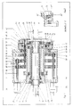
- Fig. 1 einen Längsschnitt einer erfindungsgemäßen Maschine zum Abstechen von Rohrabschnitten von einem Rohr gemäß der Schnittlinie I-I in Fig. 2;
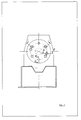
- Fig. 2 eine schematische Stirnansicht der Vorrichtung zur Verdeutlichung der Lage der verschiedenen Schnittlinien;
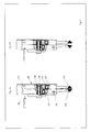
- Fig. 3 einen teilweisen Längsschnitt gemäß der Schnittlinie III-III in Fig. 2;
- Fig. 4 einen teilweisen Längsschnitt gemäß der Schnittlinie IV-IV in Fig. 2;
- Fig. 5 eine Ausbildungsabwandlung der Bewegungsumlenkungskinematik in einem teilweisen Schnitt;
- Fig. 6 die Draufsicht auf einen verspreizbaren Anfasstahlhalter, teilweise geschnitten, wobei die Abbildung a) den zusammengeschwenkten und Abbildung b) den verspreizten Zustand zeigt;
- Fig. 7 schematisch den Ablauf der Bearbeitungsgänge mit einem einteiligen Anfasstahl;
- Fig. 8 schematisch den Ablauf der Bearbeitungsgänge mit einem zweiteiligen verspreizbaren Anfasstahl.
- 1 shows a longitudinal section of a machine according to the invention for parting off pipe sections from a pipe according to section line II in FIG. 2;
- Figure 2 is a schematic front view of the device to illustrate the position of the different cutting lines.
- Figure 3 is a partial longitudinal section along the section line III-III in Fig. 2.
- Fig. 4 is a partial longitudinal section along the section line IV-IV in Fig. 2;
- 5 shows a modification of the motion redirection kinematics in a partial section;
- 6 shows the top view of an expandable handle steel holder, partially in section, the illustration a) showing the swiveled-together state and illustration b) the expanded state;
- 7 schematically shows the sequence of the machining operations with a one-piece handle.
- 8 schematically shows the course of the machining operations with a two-part expandable handle.
In einem Gehäuse 1 ist an dessen hinterem Ende ein Tragrohr 3 starr eingebaut, welches durch das Gehäuse nach vorn auskragt und in dem eine Einspannvorrichtung 5 für das Rohrwerkstück 7, und zwar dessen Vorratslänge 7a, angeordnet ist. Der abzustechende Abschnitt 7b des Rohrwerkstücks 7 ist in einer nur schematisch angedeuteten Einspannvorrichtung 9 gehalten.In a
Die Einspannvorrichtung 5 besteht aus einem Druckrohr 12, an dessen hinterem Ende ein Kolben 14 angeordnet ist, welcher durch Druckbeaufschlagung eines im hinteren Ende des Tragrohrs 3 ausgearbeiteten Zylinderraums 16 nach vorn beaufschlagbar ist. Am vorderen Ende des Druckrohrs 12 ist dessen Innenfläche konisch aufgeweitet und wirkt mit den Backen 18 einer Spannzange 20 in der Weise zusammen, daß bei einem Vorschieben des Druckrohrs 12 die Backen 18 sich fest um das Rohrwerkstück 7 schließen.The
Auf dem Tragrohr 3 ist drehbar und koaxial eine Antriebsbuchse 23 aufgesetzt und auf dieser mittels Wälzlagern 25, 26 gelagert. Das hintere Antriebsende 28 der Antriebsbuchse 23 ist zum Angriff eines nicht gezeigten Drehantriebs ausgebildet; im betrachteten Beispiel mittels einer Außenverzahnung, mit der das Zahnrad eines Antriebsmotors kämmen kann. Ebenso ist eine Ausbildung in der Weise möglich, daß das Antriebsende 28 von einer Kette oder einem Riemen eines Antriebsmotors umschlungen ist.A drive bushing 23 is rotatably and coaxially mounted on the
Am vorderen Ende der Antriebsbuchse 23 ist eine Planscheibe 30 befestigt, an deren vorderer Stirnfläche in radialen Führungen gegenüberliegend Planschieber 32, 34 verschieblich angeordnet sind. Der Planschieber 32 trägt als Werkzeug einen Abstechstahl 38. Am Planschieber 34 ist um eine Achse 40 ein Stahlhalterträger 42 schwenkbar angelenkt, der seinerseits einen Stahlhalter 44 mit einem an dessen Ende befestigten Anfasstahl 46 als Werkzeug trägt. Der Anfasstahl 46 hat vier Schneidränder, von denen je zwei unter einem Winkel zur auf der Maschinenachse rechtwinklig stehenden Querebene geneigt sind und symmetrisch zu dieser verlaufen.A
In der Nähe ihres vorderen Endes ist die Antriebsbuchse 23 mittels eines Stützlagers 50 abgestützt, welches in der Vorderwand des Gehäuses 1 eingebaut ist und dessen Innenring einen auf der Antriebsbuchse 23 sitzenden und mit diesem rotierenden Stützring 52 umschließt.In the vicinity of its front end, the drive bushing 23 is supported by a support bearing 50 which is installed in the front wall of the
Der radiale Vorschub des Abstechstahls 38 wird bewirkt durch die in der unteren Hälfte von Fig. 1 ersichtliche Kinematikkette, zu der ein Antriebsmotor 54 für den Abstechstahlvorschub gehört, welcher eine Gewindespindel 56 treibt, die mit einer Mutter 58, welche in einem Verschiebe-Außenring 60 eingebaut ist, zusammenwirkt. Zur Erzielung minimaler Reibung findet zweckmäßigerweise ein Kugelumlauf-Gewindespindeltrieb Anwendung. Im Verschiebe-Außenring 60 sitzt ein Verschiebungs-Übertragungslager 62, dessen Innenring einen mit der Antriebsbuchse 23 rotierenden und auf dieser in Axialrichtung verschieblichen Verschiebe-Innenring 64 umschließt. Durch das Verschiebungs- Übertragungslager 62 sind der Verschiebe-Außenring 60 und der Verschiebe-Innenring 64 drehbar und axial unverschieblich miteinander verbunden und eine Drehung der Gewindespindel 56 bewirkt auf diesem Wege eine Axialverschiebung des mit der Antriebsbuchse 23 rotierenden Verschiebe-Innenrings 64.The radial feed of the
Um die Zeichnung nicht zu überladen, ist nicht gezeigt, wie zur Vermeidung von Verkantungen der Verschiebe-Außenring-Innenring-Einheit bei der genannten Verschiebung im Verschiebe-Außenring 60 an der dem Motor 54 diametral gegenüberliegenden Stelle eine gleiche Mutter eingebaut ist, welche mit einer der Gewindespindel 56 entsprechenden Gewindespindel zusammenwirkt, wobei durch eine geeignete Getriebekinematik sichergestellt ist, daß die beiden Gewindespindeln sich synchron und gleichsinnig drehen. Beispielsweise sitzt im hinteren Bereich des Gehäuses auf jeder der betrachteten Gewindespindeln ein Zahnrad, das mit einem großen Zentralrad kämmt, welches auf dem hinteren Abschnitt des Tragrohrs 3 gelagert ist. Auf diese Weise wird die vom Vorschubmotor 54 erzeugte Drehbewegung der Gewindespindel 56 über das genannte Zentralrad synchron und gleichsinnig auf das gegenüberliegende Zahnrad und die mit diesem verbundene gegenüberliegende Gewindespindel übertragen.In order not to overload the drawing, it is not shown how to avoid canting of the sliding outer ring inner ring unit in the aforementioned displacement in the sliding
In den Verschiebe-Innenring 64 ist eine Schubstange 66 eingeschraubt, die nach vorn durch eine Bohrung des Stützrings 52 zur Planscheibe 30 vorragt und an deren vorderem Ende eine Lasche 68 angelenkt ist, deren anderes Ende an einem Umlenksegment 70 gelenkig angreift, welches an der Planscheibe 30 um eine Achse 72 schwenkbar ist. Das andere Ende des Umlenksegments 70 ist über eine weitere Lasche 74 gelenkig mit dem Planschieber 32 verbunden, sodaß eine Axialverschiebung der Schubstange 66 auf dem genannten Weg in einen Radialvorschub des Planschiebers 32 und damit des Abstechstahls 38 umgesetzt wird.In the sliding
In Fig. 5 ist eine Variante für die Umsetzung dieser Bewegung gezeigt. Hier findet ein um die Achse 72 schwenkbares Zahnsegment 71 Anwendung, welches mit einem vorderen Zahnstangenabschnitt der Schubstange 66' sowie mit einem rechtwinklig hierzu verlaufenden Zahnstangenansatz 73 des Planschiebers 32' kämmt. Ersichtlicherweise wird auch hier die Axialbewegung der Schubstange 66' in eine radiale Vorschubbewegung des Planschiebers 32' auf der Planscheibe 30' umgesetzt.5 shows a variant for the implementation of this movement. Here, a
In ähnlicher Weise geschieht der Vorschub des Planschiebers 34 des Anfasstahls 46. Ein Antriebsmotor 76 für den Radialvorschub des Anfasstahls treibt eine Gewindespindel 77, auf der eine Mutter 78 sitzt, welche in einem Verschiebe-Außenring 79 eingebaut ist. Zwischen diesem und einem Verschiebe-Innenring 81 sitzt ein diese drehbar und axial unverschieblich verbindendes Verschiebungs-Übertragungslager 80. Auch hier ist eine mit der Gewindespindel 77 synchronisierte, diametral gegenüberliegende Gewindespindel vorhanden, die auf eine im Verschiebe-Außenring 79 diametral gegenüberliegend sitzende Mutter wirkt. Außerdem sind im Verschiebe-Außenring 79 an zwei gegenüberliegenden Stellen Bohrungen für den Durchtritt der Gewindespindel 56 und der dieser gegenüberliegenden anderen Gewindespindel der Abstechstahl-Vorschubkinematik vorhanden.The feed of the
In den Verschiebe-Innenring 81 ist eine als Rohr ausgebildete Schubstange 82 eingeschraubt, deren vorderes Ende über wenigstens eine Lasche mit einem Umlenksegment verbunden ist, dessen anderes Ende mittels einer weiteren Lasche am Planschieber 34 angreift. Diese Bewegungsumsetzung entspricht der für den Abstechstahlvorschub beschriebenen, weshalb die hierbei mitwirkenden entsprechenden Teile nicht mehr mit eigenen Bezugszeichen versehen sind. Eine Axialverschiebung des Schubrohrs 82 wird auf die betrachtete Weise übersetzt in einen Radialvorschub des Planschiebers 34 und damit des Anfasstahls 46.A
Eine dritte Verschiebekinematik der betrachteten Art bewirkt die Schwenkung des Stahlhalterträgers 42 um die Achse 40 am Planschieber 34 und damit eine im wesentlichen in Axialrichtung verlaufende Bewegung des Anfasstahls 46.A third shift kinematics of the type under consideration causes the pivoting of the
Ein Antriebsmotor 86 ( Fig. 3) treibt eine Gewindespindel 87, die mit einer Mutter 88 in einem Verschiebe-Außenring 89 zusammenwirkt, welcher mittels eines Verschiebungs-Übertragungslagers 90 mit einem Verschiebe-Innenring 91 drehbar und axial unverschieblich verbunden ist. Auch hier ist in gleicher Weise wie bei den vorstehend beschriebenen Kinematiken eine gegenüberliegende synchron angetriebene Gewindespindel vorhanden. Im Verschiebe-Außenring 89 sind je zwei gegenüberliegende Bohrungen für den Durchtritt der Gewindespindel 77 und der zu dieser gehörenden paarigen Gewindespindel sowie der Gewindespindel 56 und der zu dieser gehörenden paarigen Gewindespindel vorhanden.A drive motor 86 (FIG. 3) drives a threaded
In den Verschiebe-Innenring 91 ist eine Schubstange 92 eingeschraubt, die nach vorn durch das Schubrohr 82 verläuft und in einem Kopf 93 endet, welcher mittels einer Gleitführung derart mit dem Stahlhalterträger 42 zusammenwirkt, daß er Bewegungen desselben in Radialrichtung nicht verhindert, Bewegungen in Axialrichtung jedoch überträgt und hierdurch Schwenkbewegungen des Stahlhalterträgers 42 um die Achse 40 erzeugt.In the sliding inner ring 91 a
Zur Gewährleistung präziser Verschiebebewegungen der Verschieberingeinheiten sind zwischen den Stirnwänden des Gehäuses 1 noch axial verlaufende Führungsstangen 95 eingebaut, welche durch entsprechende, mit Gleitbuchsen versehene Bohrungen der Verschiebe-Außenringe 60, 79, 89 greifen.To ensure precise displacement movements of the sliding ring units, axially extending
Es ist zu sehen, wie die beschriebene Ausbildung der Abstechmaschine es ermöglicht, die an der rotierenden Planscheibe 30 umlaufenden Werkzeuge Abstechstahl 38 und Anfasstahl 46 bezüglich ihres Vorschubs in Radialrichtung zu steuern und dem Anfasstahl 46 darüber hinaus Bewegungen in Axialrichtung zu erteilen.It can be seen how the training described Cut-off machine makes it possible to control the cut-off
Fig. 6 zeigt einen verspreizbaren Anfasstahlhalter 100, der im wesentlichen aus zwei schwenkbaren Armen 102, 103 besteht, an deren nach innen weisenden Enden je ein Anfasstahl 105, 106 befestigt ist. Der in der Zeichnung linker Arm 102 ist um eine radial innenliegende Achse 110 und der rechte Arm 103 um eine radial außenliegende Achse 112 um einen geringen Winkelbetrag schwenkbar. An einer in Radialrichtung zwischen den Achsen liegenden Stelle greift durch beide Arme ein Zugstab 108, dessen linkes Ende an einem gestellfesten Element befestigt ist und an dessen rechtem Ende ein Kopf ausgebildet ist, welcher in einer Ausnehmung des rechten Arms 103 liegt, wobei zwischen dem Boden dieser Ausnehmung und dem Kopf ein Tellerfederpaket 116 eingesetzt ist, das den rechten Arm 103 im Sinne einer Schwenkung im Uhrzeigersinn um die Achse 112 beaufschlagt. An einer in Radialrichtung zwischen dem Zugstab 108 und der Achse 110 des linken Arms 102 liegenden Stelle ist in den rechten Arm 103 ein Kugeleinsatz 114 eingeschraubt, dessen Kugel druckübertragend mit dem Arm 102 in Berührung steht. Die Schubstange 92 wirkt auf das radial außenliegende Ende des linken Arms 102.FIG. 6 shows a spreadable
In der in Fig. 6 a) gezeigten Grundstellung ist der rechte Arm 103 unter der Wirkung des Federpakets 116 im Sinne einer Schwenkung im Uhrzeigersinn um die Achse 112 beaufschlagt und drückt mit seinem Kugeleinsatz 114 auf die gegenüberliegende Stelle des linken Arms 102, so daß dieser im Gegenuhrzeigersinn um seine Achse 110 beaufschlagt ist. Die Arme sind zusammengeschwenkt und beide Anfasstähle 105, 106 stehen dicht beisammen.In the basic position shown in Fig. 6 a), the
Zum Verspreizen der Arme und Auseinanderbewegen der Anfasstähle drückt die Schubstange 92 auf das radial außenliegende Ende des linken Arms 102 und schwenkt diesen dadurch im Uhrzeigersinn um seine Achse 110. Durch diese Schwenkung wird der Kugeleinsatz 114 zurückgedrückt und dadurch der rechte Arm 103 im Gegenuhrzeigersinn um seine Achse 112 geschwenkt. Beide Arme bewegen sich in die in Fig. 6b gezeigte Spreizstellung, in der die Anfasstähle 105, 106 mit Abstand voneinander stehen.In order to spread the arms and move the handle steels apart, the
Mit der beschriebenen Abstechvorrichtung können verschiedene Abläufe der erforderlichen Bearbeitungsgänge verwirklicht werden, die alle gemeinsam haben, daß die in der Zeichnung linke Vorratslänge 7a des Rohrwerkstücks nicht ausgespannt und in Axialrichtung bewegt werden muß. Fig. 7 zeigt eine bevorzugte Abfolge der Bearbeitungsschritte.With the parting device described, various sequences of the required machining operations can be realized, all of which have in common that the
Nach Einspannen des Rohrwerkstücks 7 in der Einspannvorrichtung 5 sowie der Einspannvorrichtung 9 und Einschaltung des Drehantriebs der Antriebsbuchse 23 wird durch radial einwärts gerichteten Vorschub des Abstechstahls 38 der abzustechende Abschnitt 7b von der Vorratslänge 7a abgeschnitten. Danach werden durch radial einwärts gerichteten Vorschub des mittig zwischen den Schnittflächen positionierten Anfasstahls 46 die Außenränder der Schnittflächen angefast (Fig. 7a).After clamping the
Danach wird der Abstechstahl 38 zurückgefahren und der abgestochene Abschnitt 7b mittels der Einspannvorrichtung 9 von der Vorratslänge 7a weg - in den Zeichnungen nach rechts - verfahren, bis die Schnittflächen eine Entfernung voneinander aufweisen, die einen Durchtritt des Anfasstahls 46 gestattet. Der Anfasstahl 46 wird zunächst in Axialrichtung nach rechts und dann radial einwärts ins Innere zwischen den Rohrenden bewegt (Fig. 7b), worauf der Anfasstahl wieder in Axialrichtung zurück nach links sowie der abgestochene Abschnitt 7b um eine bestimmte Strecke zurück nach links so verfahren werden, daß der Anfasstahl, jetzt mit seinen rückwärtigen Schneiden den Innenrändern der Schnittflächen gegenüberliegend, mittig zwischen diesen zu stehen kommt. Jetzt werden durch einen Vorschub des Anfasstahls radial nach außen die Innenränder der Schnittflächen angefast (Fig. 7c).Thereafter, the
Schließlich wird der abgestochene Abschnitt 7b wieder nach rechts verfahren bzw. sofort ausgespannt und abtransportiert und der Anfasstahl 46 wird soweit nach rechts verfahren, bis er vom Schnittrand der Vorratslänge 7a freikommt und radial nach außen aus dem Rohrbereich zurückgezogen werden kann. Danach wird auch die Einspannung 5 gelöst und das Rohrwerkstück wird für den nächsten Schnitt vorgeschoben.Finally, the
Die vorliegend beschriebene Verfahrenssteuerung ist darauf abgestellt, daß der Anfasstahl 46 mit seinen inneren und äußeren Schneidkanten jeweils gleichzeitig beide äußeren und inneren Schnittränder von Vorratslänge 7a und abgestochenem Abschnitt 7b erfaßt. Es versteht sich, daß auch eine andere Steuerung der jeweiligen Vorschubantriebe und damit ein anderer Verfahrensablauf möglich ist. Beispielsweise können, wenn die Rückbewegung des abgestochenen Abschnitts 7b gemäß Fig. 7c als zu aufwendig erscheint, die Innenränder der Schnittflächen aufeinanderfolgend angefast werden, nämlich der Innenrand der Vorratslänge 7a durch eine Bewegung zurück nach links und der Innenrand des abgestochenen Abschnitts 7b durch eine Bewegung noch weiter nach rechts.The process control described here is based on the fact that the
In Fig. 8 sind die Bearbeitungsschritte bei Verwendung eines verspreizbaren Anfasstahlhalters 100 illustriert: Hier sind der Abstechstahl 38 und der Anfasstahlhalter 100 mit seinen Anfasstählen 105, 106 von vornherein in Axialrichtung verschieden positioniert, nämlich so, daß der Anfasstahlhalter die mittige Position zwischen den Schnittenden einnimmt, nachdem der abgestochene Abschnitt 7b nach rechts verfahren wurde.8 illustrates the processing steps when using an expandable handle steel holder 100: Here, the
Zunächst wird gemäß Fig. 8a der Abstechschnitt durchgeführt. Danach wird gemäß Fig. 8b der abgestochene Abschnitt 7b nach rechts von der Vorratslänge 7a entfernt, bis die Mittenebene des Anfasstahlhalters 100 und die Mittenebene zwischen den Schnittenden zusammenfallen. In dieser Stellung reicht der Abstand zwischen den Schnittenden zum Durchtritt der Anfasstähle bei zusammengeschwenkten Armen des Anfasstahlhalters 100 aus.First, the parting cut is carried out according to FIG. 8a. 8b, the cut-off
Zunächst werden bei gespreiztem Anfasstahlhalter die Außenränder der Schnittflächen angefast. Danach werden die Arme des Anfasstahlhalters zusammengeschwenkt, dieser wird radial einwärts verschoben und durch erneutes Spreizen werden die Innenränder der Schnittflächen angefast. Nach erneutem Zusammenschwenken der Arme des Anfasstahlhalters wird dieser radial auswärts aus dem Bereich des Rohrwerkstücks 7 bewegt und die Bearbeitung ist beendet.First, the outer edges of the cut surfaces are chamfered with the handle held apart. The arms of the handle are then swung together, this is moved radially inwards and the inner edges of the cut surfaces are chamfered by spreading again. After the arms of the grip steel holder have been pivoted again, the holder is moved radially outward from the area of the
Claims (13)
- Machine for cutting off sections (7b) of a pipe (7) which is held fixed against rotation in at least two clamping devices (5, 9) applied to each side of the cutting point respectively, and having a face plate (30) rotating on the section between the fixing points of the pipe and fixed in the axial direction, the face plate (30) carrying tools (46, 105, 106) which can be advanced in the radial direction for cutting off and chamfering the outer and the inner cut surface, whereby the clamping device fixing the pipe section to be cut off can be moved in the axial direction, characterised in that at least one of the tools (46; 105, 106) effecting the inner chamfering can be drivably moved with respect to the face plate (30) in the axial direction independently of the radial thrust movement.
- Machine according to claim 1, characterised in that the radial and axial thrust movements of the tools (38; 46; 105; 106) with respect to the face plate (30) are effected by thrust rods (66, 82, 92) which are arranged parallel to the drive shaft of the machine on a drive bushing (23) carrying the face plate (30), and are joined at their rear end to a slidable inner ring (64, 81, 91) located axially movably but held fixed against rotation on the drive bushing (23), the slidable inner ring being surrounded by a slide-transferring bearing (62, 80, 90) whose outer ring (60, 79, 89) can be moved in the axial direction with respect to the housing (1) by means of a shift drive.
- Machine according to claim 2, characterised in that the shift drive of each slidable outer ring (60, 79, 89) is formed by at least one worm gear (56, 77, 87) which cooperates with a nut (58, 78, 88) located in the slidable outer ring.
- Machine according to claim 3, characterised in that the shift drive of each slidable outer ring (60, 79, 89) is formed by a plurality of worm gears distributed uniformly over the circumference, which are joined together kinematically for synchronous rotation.
- Machine according to claims 3 and/or 4, characterised in that the worm gears with their nuts are rotating ball-worm gear drives.
- Machine according to one or more of the preceding claims, characterised in that the transfer of the axial movement of the thrust rods (66, 82) to the tools for effecting their radial thrust movement is carried out by means of a diverting segment (70) mounted in the face plate (30), at the two arc ends of which diverting segment there is articulated at least one lug (68, 74), one of which is connected to the thrust rod and the other of which is connected to a face plate (32, 34) carrying the respective tool.
- Machine according to one or more of claims 1 to 5, characterised in that the transfer of the axial movement of the thrust rods (66') to the tools for effecting their radial thrust movement is carried out by means of a toothed segment (71) mounted in the face plate (30'), the toothed segment being connected to a rack section at the end of the thrust rod (66') and to a rack attachment (73) of the face plate (32') carrying the respective tool.
- Machine according to one or more of the preceding claims, characterised in that the thrust rod cooperating in the radial thrust drive of the chamfered steel (46) is constructed as a hollow push rod (82), and the thrust rod (92) providing the axial movement of the chamfered steel (46) extends coaxially inside this push rod (82).
- Machine according to one or more of the preceding claims, characterised in that a thrust rod head (93), at the front end of the thrust rod (92) transferring the axial movement of the chamfered steel (46), is connected to the steel holder carrier (42) of the chamfered steel (46) allowing transferring forces in the axial direction and allowing radial thrust movements of the chamfered steel.
- Machine according to one or more of the preceding claims, characterised in that the steel holder carrier (42) of the chamfered steel (46) is articulated on its face plate (34) pivotably about an axis (40) which extends in the tangential direction near the outer circumference of the face plate (30).
- Machine according to one or more of the preceding claims, characterised by a one-piece chamfered steel (46) having four cut edges which form four corners, two of which are in a plane located perpendicularly to the machine axis, and the two others on a line extending parallel to the machine axis, whereby the radially-inwardly lying cut edges causing the chamfering of the outer edges of the cut surfaces on the one hand, and the radially-outwardly lying cut edges causing the chamfering of the inner edges of the cut surfaces on the other hand respectively enclose the same angles with the plane perpendicular to the machine axis.
- Machine according to one or more of claims 1 to 10, characterised by a chamfered steel holder (100), with two swivel arms (102, 103), which can be spread when stressed by the associated thrust rod (92), a chamfered steel (105, 106) being respectively secured at the end of each swivel arm.
- Machine according to claim 12, characterised in that to effect oppositely-directed swivellings one swivel arm (102) is swivelled about a radially-inwardly applied axis (110) and the other swivel arm (103) is swivelled about a radially-outwardly applied axis (112), whereby the thrust rod (92) engages outwardly on one arm (102) and this acts on a point between the axes (110, 112) transferring pressure to the other arm (103).
Applications Claiming Priority (2)
| Application Number | Priority Date | Filing Date | Title |
|---|---|---|---|
| DE4117574 | 1991-05-29 | ||
| DE4117574A DE4117574C1 (en) | 1991-05-29 | 1991-05-29 |
Publications (2)
| Publication Number | Publication Date |
|---|---|
| EP0515832A1 EP0515832A1 (en) | 1992-12-02 |
| EP0515832B1 true EP0515832B1 (en) | 1995-01-04 |
Family
ID=6432709
Family Applications (1)
| Application Number | Title | Priority Date | Filing Date |
|---|---|---|---|
| EP92106841A Expired - Lifetime EP0515832B1 (en) | 1991-05-29 | 1992-04-22 | Machine to cut off pieces of a tube |
Country Status (4)
| Country | Link |
|---|---|
| EP (1) | EP0515832B1 (en) |
| JP (1) | JPH05146903A (en) |
| AT (1) | ATE116585T1 (en) |
| DE (2) | DE4117574C1 (en) |
Families Citing this family (13)
| Publication number | Priority date | Publication date | Assignee | Title |
|---|---|---|---|---|
| DE4244042C1 (en) * | 1992-12-21 | 1994-06-23 | Mannesmann Ag | Dividing or cutting comparatively long workpieces |
| IT1270717B (en) * | 1993-09-24 | 1997-05-07 | Tubes Srl | METHOD FOR THE CUTTING AND THE AUTOMATIC TURNING OF PIPES AND CUTTING MACHINE SUITABLE TO REALIZE THE METHOD |
| FR2727886A1 (en) * | 1994-12-12 | 1996-06-14 | Combustible Nucleaire Sicn Soc | TUBE SHAPING DEVICE |
| DE10334373A1 (en) * | 2003-07-25 | 2005-02-10 | Adolf Brodbeck Maschinenbau Gmbh & Co. | Method and device for cutting and deburring pipes, especially plastic and cardboard pipes |
| GB2430399A (en) * | 2005-09-22 | 2007-03-28 | U W G Ltd | Cutting Apparatus |
| JP4711832B2 (en) * | 2006-01-13 | 2011-06-29 | 富士重工業株式会社 | Deburring device |
| IT1397296B1 (en) * | 2009-12-01 | 2013-01-04 | Ocn S P A | MACHINE FOR DRAWING AND CUTTING TO MEASURE METAL BARS. |
| AR076937A3 (en) | 2010-06-01 | 2011-07-20 | Macroplast S A | A MANUAL CUTTER / REFILER TOOL FOR LOW THICK FLEXIBLE TUBES |
| DE102012112189A1 (en) * | 2012-12-12 | 2014-06-12 | Sandvik Materials Technology Deutschland Gmbh | Device and method for cutting off a pipe |
| CN103846704B (en) * | 2013-04-08 | 2015-12-16 | 青岛海信模具有限公司 | A kind of ejector pin of die set processing tool |
| CN103331490B (en) * | 2013-07-05 | 2015-08-05 | 陈定富 | The cutting head of bearing ring cutting machine |
| ITMO20130332A1 (en) | 2013-12-06 | 2015-06-07 | Oto S P A | CUTTING MACHINE |
| DE102017120292B4 (en) * | 2017-09-04 | 2024-02-08 | Kronenberg Profil Gmbh | Separating device for pipes |
Family Cites Families (6)
| Publication number | Priority date | Publication date | Assignee | Title |
|---|---|---|---|---|
| US3563119A (en) * | 1969-04-03 | 1971-02-16 | Fairfield Machine Co Inc | Method for cutting tube members and finishing selected of the cut tube edges at a single station |
| US3724303A (en) * | 1971-04-16 | 1973-04-03 | Wm K Stamets Co | Chamfering apparatus for tubular articles |
| FR2155761A5 (en) * | 1972-12-19 | 1973-05-18 | Porier Georges | |
| US4430913A (en) * | 1982-03-23 | 1984-02-14 | Kaiser Steel Corporation | Cut-off and face machine |
| DE8706199U1 (en) * | 1987-04-29 | 1987-09-03 | F.H. Jung + Co Vertriebs Gmbh, 6521 Beselich, De | |
| DE3936176C1 (en) * | 1989-10-31 | 1990-11-22 | Maschinenfabrik Reika-Werk Gmbh, 5800 Hagen, De | Parting-off and chamfering tube stock - involves separate parting-off and chamfering tools |
-
1991
- 1991-05-29 DE DE4117574A patent/DE4117574C1/de not_active Expired - Fee Related
-
1992
- 1992-04-22 EP EP92106841A patent/EP0515832B1/en not_active Expired - Lifetime
- 1992-04-22 AT AT92106841T patent/ATE116585T1/en active
- 1992-04-22 DE DE59201120T patent/DE59201120D1/en not_active Expired - Fee Related
- 1992-05-28 JP JP4137307A patent/JPH05146903A/en not_active Withdrawn
Also Published As
| Publication number | Publication date |
|---|---|
| ATE116585T1 (en) | 1995-01-15 |
| DE59201120D1 (en) | 1995-02-16 |
| EP0515832A1 (en) | 1992-12-02 |
| DE4117574C1 (en) | 1992-07-09 |
| JPH05146903A (en) | 1993-06-15 |
Similar Documents
| Publication | Publication Date | Title |
|---|---|---|
| EP0968069B2 (en) | Machine tool | |
| EP0515832B1 (en) | Machine to cut off pieces of a tube | |
| EP2879823A1 (en) | Machine for machining pipe ends, having a centering device for centering a tubular workpiece in relation to an axis of rotation | |
| DE2230144C3 (en) | Tool support with a chisel slide that can be moved vertically therein with a tool changer assigned to the chisel slide | |
| DE1477578B2 (en) | NUMERICALLY CONTROLLED MACHINE TOOL | |
| DE2257384B2 (en) | Chucks for lathes and the like machine tools | |
| DE3441530A1 (en) | RECEIVING DEVICE FOR THE TOOL OF A CUTTING PRESS | |
| EP0469297A2 (en) | Rotatable chuck for glass tubes | |
| EP0425994A2 (en) | Method and machine for cutting off tubes and at the same time chamferring the formed tube ends | |
| DE7522786U (en) | AUXILIARY STICK WITH ROTATING CLAMPING DEVICE | |
| DE2245994A1 (en) | MULTI-SPINDLE LATHE | |
| DE3106800C2 (en) | Headstock of a machining center | |
| DE2335605B2 (en) | Feed and discharge device for workpieces of a multi-spindle automatic lathe | |
| DE2917219C2 (en) | Device for placing bead rings on the expansion building drum in a system for building pneumatic tires | |
| DE1477437C3 (en) | Tool changing device for machine tools | |
| DE877689C (en) | Pipe processing machine | |
| DE1552250B2 (en) | SHAPING LATHE | |
| DE3612960C2 (en) | ||
| DE1096156B (en) | Single or multi-spindle semi-automatic | |
| DE898839C (en) | Device and method for the arbitrary elimination and activation of the dead gear in spindle drives | |
| DE1452733C3 (en) | Machine for cutting and sifting cylindrical cans | |
| DE1284257B (en) | Device for machining and thread cutting on pipe ends | |
| DE1602036B2 (en) | Pilger mill for reducing the diameter of pipes | |
| DE1911696A1 (en) | Tool transfer device for automatic machine tools | |
| EP0417530A1 (en) | Multi-spindle automatic lathe with a limit stop |
Legal Events
| Date | Code | Title | Description |
|---|---|---|---|
| PUAI | Public reference made under article 153(3) epc to a published international application that has entered the european phase |
Free format text: ORIGINAL CODE: 0009012 |
|
| AK | Designated contracting states |
Kind code of ref document: A1 Designated state(s): AT BE CH DE DK ES FR GB IT LI NL SE |
|
| 17P | Request for examination filed |
Effective date: 19930403 |
|
| 17Q | First examination report despatched |
Effective date: 19940427 |
|
| GRAA | (expected) grant |
Free format text: ORIGINAL CODE: 0009210 |
|
| AK | Designated contracting states |
Kind code of ref document: B1 Designated state(s): AT BE CH DE DK ES FR GB IT LI NL SE |
|
| PG25 | Lapsed in a contracting state [announced via postgrant information from national office to epo] |
Ref country code: NL Effective date: 19950104 Ref country code: ES Free format text: THE PATENT HAS BEEN ANNULLED BY A DECISION OF A NATIONAL AUTHORITY Effective date: 19950104 Ref country code: DK Effective date: 19950104 Ref country code: BE Effective date: 19950104 |
|
| REF | Corresponds to: |
Ref document number: 116585 Country of ref document: AT Date of ref document: 19950115 Kind code of ref document: T |
|
| ET | Fr: translation filed | ||
| REF | Corresponds to: |
Ref document number: 59201120 Country of ref document: DE Date of ref document: 19950216 |
|
| ITF | It: translation for a ep patent filed |
Owner name: DR. ING. AUSSERER ANTON |
|
| PG25 | Lapsed in a contracting state [announced via postgrant information from national office to epo] |
Ref country code: SE Effective date: 19950404 |
|
| PG25 | Lapsed in a contracting state [announced via postgrant information from national office to epo] |
Ref country code: AT Effective date: 19950422 |
|
| GBT | Gb: translation of ep patent filed (gb section 77(6)(a)/1977) |
Effective date: 19950328 |
|
| PG25 | Lapsed in a contracting state [announced via postgrant information from national office to epo] |
Ref country code: LI Effective date: 19950430 Ref country code: CH Effective date: 19950430 |
|
| NLV1 | Nl: lapsed or annulled due to failure to fulfill the requirements of art. 29p and 29m of the patents act | ||
| PGFP | Annual fee paid to national office [announced via postgrant information from national office to epo] |
Ref country code: FR Payment date: 19951030 Year of fee payment: 4 |
|
| PLBE | No opposition filed within time limit |
Free format text: ORIGINAL CODE: 0009261 |
|
| STAA | Information on the status of an ep patent application or granted ep patent |
Free format text: STATUS: NO OPPOSITION FILED WITHIN TIME LIMIT |
|
| REG | Reference to a national code |
Ref country code: CH Ref legal event code: PL |
|
| 26N | No opposition filed | ||
| PG25 | Lapsed in a contracting state [announced via postgrant information from national office to epo] |
Ref country code: GB Effective date: 19960422 |
|
| GBPC | Gb: european patent ceased through non-payment of renewal fee |
Effective date: 19960422 |
|
| PG25 | Lapsed in a contracting state [announced via postgrant information from national office to epo] |
Ref country code: FR Effective date: 19961227 |
|
| REG | Reference to a national code |
Ref country code: FR Ref legal event code: ST |
|
| PGFP | Annual fee paid to national office [announced via postgrant information from national office to epo] |
Ref country code: DE Payment date: 19970428 Year of fee payment: 6 |
|
| PG25 | Lapsed in a contracting state [announced via postgrant information from national office to epo] |
Ref country code: DE Free format text: LAPSE BECAUSE OF NON-PAYMENT OF DUE FEES Effective date: 19990202 |
|
| PG25 | Lapsed in a contracting state [announced via postgrant information from national office to epo] |
Ref country code: IT Free format text: LAPSE BECAUSE OF NON-PAYMENT OF DUE FEES;WARNING: LAPSES OF ITALIAN PATENTS WITH EFFECTIVE DATE BEFORE 2007 MAY HAVE OCCURRED AT ANY TIME BEFORE 2007. THE CORRECT EFFECTIVE DATE MAY BE DIFFERENT FROM THE ONE RECORDED. Effective date: 20050422 |