EP0514874A2 - Toner feeding device - Google Patents
Toner feeding device Download PDFInfo
- Publication number
- EP0514874A2 EP0514874A2 EP92108531A EP92108531A EP0514874A2 EP 0514874 A2 EP0514874 A2 EP 0514874A2 EP 92108531 A EP92108531 A EP 92108531A EP 92108531 A EP92108531 A EP 92108531A EP 0514874 A2 EP0514874 A2 EP 0514874A2
- Authority
- EP
- European Patent Office
- Prior art keywords
- toner
- housing
- downstream
- feeding device
- disposed
- Prior art date
- Legal status (The legal status is an assumption and is not a legal conclusion. Google has not performed a legal analysis and makes no representation as to the accuracy of the status listed.)
- Granted
Links
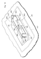
Images


Classifications
-
- G—PHYSICS
- G03—PHOTOGRAPHY; CINEMATOGRAPHY; ANALOGOUS TECHNIQUES USING WAVES OTHER THAN OPTICAL WAVES; ELECTROGRAPHY; HOLOGRAPHY
- G03G—ELECTROGRAPHY; ELECTROPHOTOGRAPHY; MAGNETOGRAPHY
- G03G15/00—Apparatus for electrographic processes using a charge pattern
- G03G15/06—Apparatus for electrographic processes using a charge pattern for developing
- G03G15/08—Apparatus for electrographic processes using a charge pattern for developing using a solid developer, e.g. powder developer
- G03G15/0822—Arrangements for preparing, mixing, supplying or dispensing developer
- G03G15/0877—Arrangements for metering and dispensing developer from a developer cartridge into the development unit
-
- G—PHYSICS
- G03—PHOTOGRAPHY; CINEMATOGRAPHY; ANALOGOUS TECHNIQUES USING WAVES OTHER THAN OPTICAL WAVES; ELECTROGRAPHY; HOLOGRAPHY
- G03G—ELECTROGRAPHY; ELECTROPHOTOGRAPHY; MAGNETOGRAPHY
- G03G15/00—Apparatus for electrographic processes using a charge pattern
- G03G15/06—Apparatus for electrographic processes using a charge pattern for developing
- G03G15/08—Apparatus for electrographic processes using a charge pattern for developing using a solid developer, e.g. powder developer
- G03G15/0822—Arrangements for preparing, mixing, supplying or dispensing developer
- G03G15/0848—Arrangements for testing or measuring developer properties or quality, e.g. charge, size, flowability
- G03G15/0856—Detection or control means for the developer level
- G03G15/0858—Detection or control means for the developer level the level being measured by mechanical means
Landscapes
- Physics & Mathematics (AREA)
- General Physics & Mathematics (AREA)
- Dry Development In Electrophotography (AREA)
Abstract
Description
- The present invention relates to a toner feeding device applied to an electrostatic latent image developing apparatus which is mounted on an electrostatic copying machine, a laser beam printing machine and like.
- In an electrostatic latent image developing device mounted on an electrostatic copying machine or a laser beam printing machine, the toner is applied to the electrostatic latent image to develop a toner image. Therefore, the toner is consumed as the execution of developing proceeds. The developing device is usually equipped with a toner feeding device to feed toner to the developing device if need arises.
- A typical toner feeding device has a housing in which a toner container is disposed at an upstream end and a toner sending means is disposed at a downstream end. In the housing is disposed a toner conveying means which conveys the toner discharged to the upstream portion of the housing from the toner container to the downstream portion of the housing. The toner sending means disposed at the downstream end of the housing sends the toner to the developing means, as required. From the standpoint of designing as a whole the electrostatic copying machine or the laser beam printing machine, it often becomes necessary to extend the housing to a relatively long extent from the upstream end where the toner container is disposed up to the downstream end where the toner sending means is disposed. In such a case, a plurality of the toner conveying means must be provided in the housing. Each toner conveying means is composed, for example, of a rotary member having a conveying rod portion that extends substantially in parallel with the center axis of rotation. When the rotary member is rotated in the predetermined direction, the toner is conveyed by the action of the conveying rod portion. The toner sending means and the toner conveying means are connected to a common drive means and both of them are actuated when the toner is to be sent to the developing device.
- Here, the conventional toner feeding device of the form described above involves the following problems that must be solved.
- First, a plurality of toner conveying means disposed in the housing are all started or stopped simultaneously and the toner is usually conveyed in an excess amount from the upstream portion to the downstream portion. Therefore, the toner tends to be compressed and agglomerated at the downstream portion of the housing, or an excess of load acts upon the toner conveying means disposed at the downstream portion and further acts upon the drive means. The above problems can be solved if the amount of toner conveyed by the toner conveying means is corresponded fully precisely to the amount of toner sent by the toner sending means. This, however, is virtually impossible or quite difficult. If the amount of toner conveyed by the toner conveying means is set to be smaller than the amount of toner sent by the toner sending means, the toner is not fed in sufficient amounts to the developing device. Usually, therefore, the amount of toner conveyed by the toner conveying means is set to be slightly greater than the amount of toner sent by the toner sending means.
- Second, when the amount of toner in the toner feeding device becomes small as a result of its consumption, it becomes necessary to replenish the toner container disposed at the upstream end of the housing with the toner or to renew the toner container itself. Therefore, the conventional toner feeding device is provided with a special detector means for detecting the toner in the toner container. This is one of causes to obstruct a reduction in the manufacturing cost.
- Third, it is desired to detect the amount of toner that exists at the downstream portion of the housing in relation to solving the above first and second problems or separately therefrom. However, there is not available a simply and at-low-cost constructed detector means which is capable of detecting the amount of toner at the downstream portion of the housing without posing such problems as scattering of toner from the housing.
- It is, therefore, a first object of the present invention to provide a novel and improved toner feeding device which reliably prevents the amount of toner from becoming too small or too large at the downstream portion of the housing, and thus solves the above first problem inherent in the conventional toner feeding device.
- It is a second object of the present invention to provide a novel and improved toner feeding device which detects the necessity of replenishing the toner feeding device with the toner based upon the amount of toner detected at the downstream portion of the housing in relation to or separately from solving the above first technical problem, without the need of detecting the amount of toner in the toner container.
- It is a third object of the present invention to provide a novel and improved toner feeding device equipped with a toner amount detector means which is capable of detecting the amount of toner as required at the downstream portion of the housing without posing such a problem as scattering of toner from the housing.
- Other objects of the present invention will become apparent from the following detailed description of an embodiment of a toner feeding device constructed according to the present invention, by reference to the accompanying drawings.
- In order to achieve the above first object according to the present invention, there is provided a toner feeding device comprising:
- a housing,
- a toner container disposed at the upstream end of said housing,
- a toner sending means disposed at the downstream end of said housing,
- a toner conveying means for conveying the toner discharged from said toner container toward said toner sending means through said housing,
- a drive means for driving said toner conveying means,
- a control means for controlling the energization and de-energization of said drive means, and
- said toner conveying means including at least one upstream-side toner conveying means disposed at the upstream portion in said housing and at least one downstream-side toner conveying means disposed at the downstream portion in said housing; wherein
- said drive means includes an upstream side drive means for driving said upstream side toner conveying means and a downstream side drive means for driving said downstream side toner conveying means;
- a toner amount detector means is disposed to detect the amount of toner that exists at the downstream portion of said housing; and
- said control means does not allow to energize said upstream side drive means when the amount of toner detected by said toner amount detector means is greater than a predetermined amount.
- In order to achieve the above second object according to the present invention, furthermore, there is provided a toner feeding device comprising:
- a housing,
- a toner container disposed at the upstream end of said housing,
- a toner sending means disposed at the downstream end of said housing,
- a toner conveying means for conveying the toner discharged from said toner container toward said toner sending means through said housing,
- a drive means for driving said toner conveying means,
- a control means for controlling the energization and de-energization of said drive means, and
- said toner conveying means including at least one upstream-side toner conveying means disposed at the upstream portion in said housing and at least one downstream-side toner conveying means disposed at the downstream portion in said housing; wherein
- a toner amount detector means is disposed to detect the amount of toner that exists at the downstream portion of said housing; and
- said control means gives a toner replenishment signal when the amount of toner detected by said toner amount detector means is smaller than a predetermined amount irrespective of when said upstream side toner conveying means is operated for more than a predetermined period of time.
- Moreover, in order to achieve the above third object according to the present invention, there is provided a toner feeding device comprising:
- a housing,
- a toner container disposed at the upstream end of said housing,
- a toner sending means disposed at the downstream end of said housing,
- a toner conveying means for conveying the toner discharged from said toner container toward said toner sending means through said housing,
- a drive means for driving said toner conveying means,
- a control means for controlling the energization and de-energization of said drive means, and
- said toner conveying means including at least one upstream-side toner conveying means disposed at the upstream portion in said housing and at least one downstream-side toner conveying means disposed at the downstream portion in said housing; wherein
- a toner amount detector means is disposed to detect the amount of toner that exists at the downstream portion of said housing; and
- said toner amount detector means is rotatably mounted inside the downstream portion of said housing and is constituted by a rotary plate that comes in contact with the upper surface of the toner existing at the downstream portion of said housing and a detector which detects said rotary plate.
- Similarly, in order to achieve the above third object according to the present invention, there is provided a toner feeding device comprising:
- a housing,
- a toner container disposed at the upstream end of said housing,
- a toner sending means disposed at the downstream end of said housing;
- a toner conveying means for conveying the toner discharged from said toner container toward said toner sending means through said housing,
- a drive means for driving said toner conveying means,
- a control means for controlling the energization and de-energization of said drive means, and
- said toner conveying means including at least one upstream-side toner conveying means disposed at the upstream portion in said housing and at least one downstream-side toner conveying means disposed at the downstream portion in said housing; wherein
- a toner amount detector means is disposed to detect the amount of toner that exists at the downstream portion of said housing, said toner amount detector means being allowed to ascend and descend in the downstream portion of said housing, and being constituted by an ascend/descend member that ascends or descends in accordance with the amount of toner that exists in the downstream portion of said housing and a detector which detects said ascend/descend member.
- In the toner feeding device constructed according to the present invention, operation of the upstream side toner conveying means which conveys the toner from the upstream portion of the housing toward the downstream portion is controlled separately from the operation of the downstream side toner conveying means disposed at the downstream portion of the housing or separately from the operation of the toner sending means disposed at the downstream end of the housing, and the amount of toner is suitably maintained and is reliably prevented from becoming too small or too large at the downstream portion of the housing.
- In the toner feeding device constructed according to the present invention, furthermore, the necessity for replenishing the toner feeding device with the toner is suitably detected upon detecting that the amount of toner at the downstream portion of the housing does not exceed a predetermined amount irrespective of when the upstream side toner conveying means is operated for more than a predetermined period of time.
- In the toner feeding device constructed according to the present invention, furthermore, the amount of toner at the downstream portion of the housing is suitably detected by a simply and at-low-cost constructed toner amount detector which is disposed at the downstream portion of the housing and which includes a swing plate or an ascend/descend member, without posing such a problem as scattering of toner from the housing.
-
- Fig. 1 is a vertical sectional view which illustrates a preferred embodiment of a toner feeding device constructed according to the present invention, together with a rotary drum and a developing device;
- Fig. 2 is a horizontal sectional view illustrating a portion of the toner feeding device of Fig. 1;
- Fig. 3 is a schematic diagram illustrating a drive system in the toner feeding device of Fig. 1;
- Fig. 4 is a vertical sectional view illustrating the operation of a toner amount detector means (in the case where the toner exists in an amount more than a predetermined amount in the downstream portion of the housing) in the toner feeding device of Fig. 1;
- Fig. 5 is a vertical sectional view illustrating the operation of the toner amount detector means (in the case where the toner does not exist in an amount more than a predetermined amount in the downstream portion of the housing) in the toner feeding device of Fig. 1;
- Fig. 6 is a flow chart illustrating a main routine in the operation mode of the toner feeding device of Fig. 1;
- Fig. 7 is a flow chart illustrating a subroutine in the operation mode of the toner feeding device of Fig. 1;
- Fig. 8 is a vertical sectional view illustrating the operation of the toner amount detector means (in the case where the toner exists in an amount more than a predetermined amount in the downstream portion of the housing) in a modified embodiment of the toner feeding device constructed according to the present invention;
- Fig. 9 is a vertical sectional view illustrating the operation of the toner amount detector means (in the case where the toner does not exist in an amount more than a predetermined amount in the downstream portion of the housing) in the modified embodiment shown in Fig. 8;
- Fig. 10 is a partial perspective view showing a portion of the toner amount detector means in the modified embodiment of Fig. 8;
- Fig. 11 is a perspective view showing an ascend/descend member in the toner amount detector means in the modified embodiment of Fig. 8;
- Fig. 12 is a partial perspective view illustrating the operation of the toner amount detector means (in the case where the toner exists in an amount more than a predetermined amount in the downstream portion of the housing) in the modified embodiment of Fig. 8; and
- Fig. 13 is a partial perspective view illustrating the operation of the toner amount detector means (in the case where the toner does not exist in an amount more than a predetermined amount in the downstream portion of the housing) in the modified embodiment of Fig. 8.
- A preferred embodiment of the toner feeding device constructed according to the present invention will now be described in detail with reference to the accompanying drawings.
- Fig. 1 shows a preferred embodiment of the toner feeding device constructed according to the present invention that is generally designated at 6, together with a
rotary drum 2 and a developingdevice 4. - An electrostatic photosensitive member is arranged on the peripheral surface of the
rotary drum 2, an electrostatic latent image is formed on the photosensitive member on the upstream side of a developingzone 10 while therotary drum 2 is rotated in a direction indicated byarrow 8, and the toner is applied to the electrostatic latent image on the photosensitive member in the developingzone 10 by the action of the developingdevice 4 to develop a toner image. The toner image on the photosensitive member is transferred onto a transfer paper which may be a common paper on the downstream side of the developingzone 10, whereby a copy or a print is produced. - The illustrated developing
device 4 is provided with a developinghousing 12 which has a developingopening 14 formed in the right side surface thereof and a toner-receiving opening 16 formed at the upper left end portion thereof. In the developinghousing 12 are arranged amagnetic brush mechanism 18, and agitatingmechanisms housing 12 is held adeveloper 23 which consists of a toner and a carrier. The agitatingmechanisms developer 23 in the developinghousing 12, so that the toner is frictionally charged to have a predetermined polarity. Themagnetic brush mechanism 18 is constituted by asleeve member 30 rotated in the direction indicated byarrow 28 and a stationarypermanent magnet 32 disposed in thesleeve member 30. Thedeveloper 23 is magnetically held on the peripheral surface of thesleeve member 30 and is carried onto the developingzone 10 thereby to apply the toner to the electrostatic latent image formed on the photosensitive member arranged on the peripheral surface of therotary drum 2. The toner in thedeveloper 23 is consumed as the developing is performed; therefore, the toner is fed into the developinghousing 12 from thetoner feeding device 6 in accordance with the consumption of toner. - The
rotary drum 2 and the developingdevice 4 are examples of a developing device to which thetoner feeding device 6 of the present invention is applied and a rotary drum on which an electrostatic latent image is formed, and may be the one well known among people skilled in the art. Therefore, the detailed description of therotary drum 2 and developingdevice 4 is not made in this specification. - With further reference to Fig. 1, the
toner feeding device 6 according to the present invention is provided with ahousing 34 which can be made of a suitable synthetic resin. Thehousing 34 has a toner container-mountingportion 36 formed in the upper surface at the upstream end portion thereof and has atoner sending opening 38 formed in the lower surface at the downstream end portion thereof. More detailedly, anupper wall portion 40 is arranged extending substantially horizontally on the upper surface of the upstream end (left end) of thehousing 34. In theupper wall portion 40 is formed anopening 41 that extends in the direction of width (direction perpendicular to the surface of the paper in Fig. 1). On both sides of theupper wall portion 40 are formed a pair ofsupport walls toner container 48 holdingtoner 46 is detachably mounted on the toner container-mountingportion 36 that is defined by theupper wall portion 40 and the pair ofsupport walls toner container 48 is of a box shape that extends oblongly in the width direction, and has a funnel-shapedportion 50 formed at the lower portion thereof under the condition shown in Fig. 1 with its both side walls that are downwardly tilted in the directions to gradually approach each other. Adischarge port 52 is formed at the lower end of the funnel-shaped portion to extend in the width direction. A mountingflange 54 is formed at the lower end of thetoner container 48 to protrude toward both sides from thedischarge port 52. As shown in Fig. 1, thetoner container 48 is positioned in theopening 41 of thehousing 34 with itsdischarge port 52 being faced downwards and is mounted on the toner container-mountingportion 36 of thehousing 34 by positioning the mountingflange 54 on the upstream sideupper wall portion 40 of thehousing 34. The pair ofsupport walls housing 34 sustain hold main portions of both side walls of thetoner container 48. Thedischarge port 52 of thetoner container 48 is sealed with a suitable sealing member (not shown). After thetoner container 48 is mounted on thehousing 34 as required, the sealing member is removed to open thedischarge port 52. Then, thetoner 46 held in thetoner container 48 is discharged into the upstream end portion (left end in Fig. 1) of thehousing 34 through thedischarge port 52 and theopening 41. - The lower walls of the
housing 34 are downwardly tilted in the directions to gradually approach each other on both sides of thetoner sending opening 38 formed in the lower surface at the downstream end of thehousing 34 of thetoner feeding device 6, thereby to define a sendingportion 56 of an inverted trapezoidal shape in cross section. A toner sending means 58 is disposed in the sendingportion 56. The toner sending means 58 in the illustrated embodiment is constituted by a sendingroller 60 that extends in the width direction (direction perpendicular to the surface of the paper in Fig. 1). With reference to Fig. 2 together with Fig. 1, a sendingroller 60 which can be made of a sponge has arotary shaft 62 which extends substantially horizontally in the width direction and which is rotatably mounted between afront wall 64 and arear wall 66 of thehousing 34. As will be described later, the sendingroller 60 is selectively rotated in a direction indicated byarrow 68 and, thus, thetoner 46 is sent into the developinghousing 12 of the developingdevice 4 through thetoner sending opening 38 of thehousing 34. - In the
housing 34 of thetoner feeding device 6 is disposed a toner conveying means that is generally designated at 70 in order to convey thetoner 46 discharged onto the upstream end of thehousing 34 from thetoner container 48 toward the toner sending means 58. The toner conveying means 70 of the illustrated embodiment includes two upstream-sidetoner conveying means toner conveying means housing 34 are formed fourarcuate portions toner conveying means toner conveying means toner conveying devices toner conveying devices rotary shafts front wall 64 and therear wall 66 of thehousing 34.Rotary members rotary shafts rotary member 102 hascoupling portions 110 that extend in the radial direction from both ends of therotary shaft 94 and a conveyingrod portion 118 that extends substantially in parallel with the rotary shaft 94 (i.e., substantially horizontally) between thecoupling portions 110. Similarly, otherrotary members rotary shafts rotary shafts toner conveying means toner conveying means arrows 68. The conveying rod portions of therotary members arcuate portions housing 34 in order to move thetoner 46 in thehousing 34 from the left toward the right in Fig. 1. The downstream-sidetoner conveying means 78 is further provided with anauxiliary rotary member 120 which hascoupling portions 122 that extend in the radial direction from therotary shaft 94 on the inside of thecoupling portion 110 of therotary member 102 in the width direction (axial direction) and anauxiliary rod portion 124 that extends on the inside in the radial direction between theabove coupling portions 122 in parallel with the conveyingrod portion 118 of therotary member 102. As will be clearly understood from - Fig. 1, the
auxiliary rotary member 120 is secured to acommon rotary shaft 94 and deviated by a predetermined angle which may be about 50 degrees in the direction of rotation indicated byarrow 68 with respect to therotary member 102. Therefore, theauxiliary rotary member 120 is rotated together with therotary member 102 in the direction indicated byarrow 68. - With reference to Fig. 3 together with Figs. 1 and 2, two drive means, i.e., an upstream-side drive means 126 and a downstream-side drive means 128 are arranged on the outer surface (back) of the
rear wall 66 of thehousing 34. Anoutput gear 130 is fastened to the output shaft of the upstream-side drive means 126 which may be an electric motor. Therotary shafts toner conveying means rear wall 66, and input gears 132 and 134 are secured to the protruded ends. As clearly shown in Fig. 3, furthermore, theoutput gear 130 is brought into engagement with the input gears 132 and 134. When the upstream-side drive means 126 is energized, therefore, the upstream-sidetoner conveying means arrow 68. Anoutput gear 136 is secured to the output shaft of the downstream-side drive means 128 which may similarly be an electric motor. On the other hand, therotary shafts toner conveying means rear wall 66, and input gears 138 and 140 are secured to the protruded ends thereof. Moreover, therotary shaft 62 of the toner sending means 58 rearwardly protrudes penetrating through therear wall 66, and aninput gear 142 is secured to the protruded end thereof. Theoutput gear 136 of the downstream-side drive means 128 is brought into engagement with input gears 138 and 140. In addition, theinput gear 140 is engaged with theinput gear 142 via atransmission gear 144. When the downstream-side drive means 128 is energized, therefore, the downstream sidetoner conveying devices arrow 68, and the toner sending means 58 is rotated in the direction indicated byarrow 68. - With reference to Figs. 1 and 2, a toner amount detector means 146 is disposed in the
toner feeding device 6 to detect the amount of toner that exists at the downstream portion of thehousing 34. The toner amount detector means 146 in the illustrated embodiment includes arotary plate 148. Asupport shaft 150 is mounted between thefront wall 64 and therear wall 66 of thehousing 34. Upright mountingpieces 152 are formed on both sides at the base end of aswing plate 148 as a unitary structure, thesupport shaft 150 is inserted through the mountingpieces 152, and theswing plate 148 is swingably mounted at the front end of thesupport shaft 150. Apermanent magnet 154 is fastened to the front end (portion neighboring the front end of the housing 34) of theswing plate 148. Adetector 156 constituted by a reed switch is secured at a predetermined position on the outer surface (front surface) offront wall 64 of thehousing 34 to detect apermanent magnet 154 of theswing plate 148. - When the
toner 46 exists in a sufficiently large amount in the downstream portion of thehousing 34 as shown in Fig. 4, the free end of theswing plate 148 comes in contact with the upper surface of thetoner 46, whereby theswing plate 148 is maintained at a relatively high position and thedetector 156 does not detect thepermanent magnet 154. When the amount oftoner 46 becomes reduced in the downstream portion of thehousing 34, as shown in Fig. 5, theswing plate 148 turns in the clockwise direction and thedetector 156 detects thepermanent magnet 154. As will be easily understood by reference to Fig. 5, when theswing plate 148 is lowered with the reduction in the amount of thetoner 46 in the downstream portion of thehousing 34, theswing plate 148 protrudes into the loci of rotation of the conveyingrod portion 118 ofrotary member 102 and theauxiliary rod portion 124 of auxiliaryrotary member 120 in the downstream-sidetoner conveying means 78. Therefore, when the downstream-sidetoner conveying means 78 is rotated in the direction indicated byarrow 68, theauxiliary rod portion 124 of theauxiliary rotary member 120 first acts on theswing plate 148 to turn it in the counterclockwise direction to raise it and then, the conveyingrod portion 118 of therotary member 102 acts on theswing plate 148 to further turn it in the counterclockwise direction to raise it. Then, as therotary member 102 discontinues to act thereon, theswing plate 148 again turns in the clockwise direction due to its own weight, and is lowered to the illustrated position i.e., to a position at which thedetector 156 detects thepermanent magnet 154. As the amount oftoner 46 becomes smaller than a predetermined value at the downstream portion of thehousing 34, therefore, thedetector 156 periodically detects thepermanent magnet 154 while the downstream-sidetoner conveying means 74 is rotated in the direction indicated byarrow 68. Theswing plate 148 is reciprocatingly rotated in the counterclockwise direction and the clockwise direction in accordance with the motion of the downstream-sidetoner conveying means 78. Thus, theswing plate 148 is completely prevented from occurrence of trouble of turning such as blocking of turning that might occur when thetoner 46 is clogged between the mountingpieces 152 of theswing plate 148 and thesupport shaft 150. Even when there exists thetoner 46 in a sufficiently large amount in the downstream portion of thehousing 34 as shown in Fig. 4, the upper surface of thetoner 46 rises or lowers periodically somewhat by the rotation of the downstream-side toner conveying means 78 in the direction indicated byarrow 68, whereby theswing plate 148 is reciprocatingly rotated to some extent and is reliably prevented from defectively rotating. - In the illustrated embodiment, furthermore, attention should further be given to the following fact. When the downstream-side
toner conveying means 78 is not provided with theauxiliary rotary member 120, theswing plate 148 does not ascend until the conveyingrod portion 118 of therotary member 102 acts directly on theswing plate 148. In this case, theswing plate 148 interferes thetoner 46 that is moved toward the toner sending means 58 by the action of the conveyingrod portion 118 of therotary member 102, and thetoner 46 is pressed onto theswing plate 148; i.e., thetoner 46 is hindered from being smoothly conveyed toward the toner sending means 58 and tends to be compressed and agglomerated. In the illustrated embodiment in which the downstream sidetoner conveying means 78 is provided with theauxiliary rotary member 120, on the other hand, theauxiliary rod portion 124 of theauxiliary rotary member 120 acts on theswing plate 148 to raise it before therotary member 102 acts on theswing plate 148. This helps sufficiently maintain a path along which thetoner 46 moves toward the toner sending means 58, and hence, thetoner 46 is allowed to move very smoothly toward the toner sending means 58 by the action of the conveyingrod portion 118 of therotary member 102. - Described below are the action operation of the above-mentioned
toner feeding device 6, and modes operations for controlling the upstream-sidetoner conveying means toner conveying means - Energization and de-energization of the upstream-side drive means 126 and the downstream-side drive means 128 of the
toner feeding device 6 can be controlled by a control means (not shown) that can be constituted by a microprocessor. Reference is made to a flow chart of Fig. 6 together with Fig. 1. When the downstream-side drive means 128 that is under being energized, it is de-energized in the step n-1. Then, a step n-2 discriminates whether there is given a toner feed signal that shows the necessity of feeding thetoner 46 to the developingdevice 4. When the toner concentration (ratio of toner to the carrier) in the developingagent 23 hold in the developinghousing 12 of developingdevice 4 becomes smaller than a predetermined value, a toner feed signal is produced. The toner concentration in the developinghousing 12 can be detected by a suitable known detector (not shown). When the toner feed signal is not produced, the program returns to the above step n-1. When the toner feed signal is produced, the program proceeds to a step n-3 where the downstream-side drive means 128 is energized and, hence, the downstream-sidetoner conveying means housing 34 of thetoner feeding device 6, therefore, the toner is conveyed toward the toner sending means 58 by the action of the downstream-sidetoner conveying means toner 46 is supplied from thetoner feeding device 6 to the developinghousing 12 of the developingdevice 4 by the action of the toner sending means 58. The program then proceeds to a step n-4 where it is discriminated whether thedetector 156 in the toner amount detector means 146 detects thepermanent magnet 154 mounted on theswing plate 148 or not. When there exists thetoner 46 in an amount greater than a predetermined amount in the downstream portion of thehousing 34 oftoner feeding device 6, thedetector 156 does not detect thepermanent magnet 154. When thetoner 46 does not exist in an amount greater than a predetermined amount in the downstream portion of thehousing 34, on the other hand, thedetector 156 periodically detects the permanent magnet 154 (since the downstream-sidetoner conveying means 78 is rotated). When thedetector 156 does not detect thepermanent magnet 154, the program returns to the step n-2. The program is shifted from the main routine to a subroutine when thepermanent magnet 154 is detected by thedetector 156. - With reference to Fig. 7, the upstream-side drive means 126 is energized at a step m-1 in the subroutine and, hence, hence, the upstream-side
toner conveying means housing 34 oftoner feeding device 6, therefore, thetoner 46 is also conveyed toward the downstream side by the action of the upstream sidetoner conveying means toner 46 to the developingdevice 4 like at the step n-2 in the main routine. When the toner feed signal is not produced, the program proceeds to a step m-3 where the upstream-side drive means 126 is de-energized, and the upstream-sidetoner conveying means toner conveying means toner conveying means permanent magnet 154 mounted on theswing plate 148 is detected by thedetector 156 of the toner amount detector means 146 or not like at the step n-4 of the main routine. When thepermanent magnet 154 is not detected by thedetector 156, the program proceeds to a step m-7 where it is discriminated whether there is produced a toner feed signal that shows the necessity of feeding thetoner 46 to the developinghousing 12 of developing device. When there is given no toner feed signal, the program returns to the main routine therefore, the downstream-side drive means 128 is de-energized too at the step n-1 of the main routine, and the downstream-sidetoner conveying means permanent magnet 154 is detected by thedetector 156 of the toner amount detector means 146. When there does not exist thetoner 46 in an amount greater than a predetermined amount on the downstream-side of thehousing 34 under the condition where the downstream-side drive means 128 is energized and the downstream-sidetoner conveying means 78 is rotated, thedetector 156 detects thepermanent magnet 154 not consecutively but periodically as described above. It is therefore necessary for thedetector 156 to discriminate whether thepermanent magnet 154 is detected or not for more than a predetermined period of time (for at least more than a period of time required for the downstream-side toner conveying means 78 to make one rotation). Therefore, in the step m-8 it is discriminated whether a predetermined period of time has passed after the upstream side drive means 126 was de-energized, and the program returns to the step m-6 when the predetermined period of time has not passed. - When the upstream-side drive means 126 is energized for more than a predetermined period of time (step m-4), the upstream-side
toner conveying means detector 156 of the toner amount detector means 146 does not detect thepermanent magnet 154 for more than a predetermined period of time in the step m-6 (step m-8) and thetoner 46 does not exist in an amount more than a predetermined amount in the downstream portion of thehousing 34, it means that thetoner 46 to be conveyed to the downstream portion of thehousing 34 does not exist in the upstream portion of thehousing 34 and hence, thetoner 46 does not exist in thetoner container 48. In such a case, the toner replenishment signal is produced, and thetoner container 48 must be replaced by a new one containing thetoner 46 in a required amount or thetoner container 48 must be replenished with thetoner 46. When the toner container is renewed or the toner is replenished as required, the toner replenishment signal is no more given. In thetoner feeding device 6 constituted according to the present invention, therefore, whether thetoner container 48 needs be replenished with the toner or not is also detected by utilizing the detection by thedetector 156 which detects whether there exists thetoner 46 in an amount greater than a predetermined amount in the downstream portion of thehousing 34. The program returns to the step m-1 when the predetermined period of time has passed at the step m-8. - In the illustrated
toner feeding device 6 constituted according to the present invention, the upstream-sidetoner conveying means toner 46 in an amount greater than the predetermined amount in the downstream portion of thehousing 34. When there exists thetoner 46 in an amount greater than the predetermined amount in the downstream portion of thehousing 34, the upstream sidetoner conveying means toner conveying means toner 46 from being compressed and agglomerated at the downstream portion of thehousing 34, and further prevents thetoner 46 from creating excess resistance to the downstream-sidetoner conveying means - In the illustrated embodiment, operations of the upstream-side
toner conveying means toner conveying means toner conveying means toner conveying means toner conveying means - Figs. 8 to 13 illustrate a modified embodiment in which the toner detector means and the related constitution are modified. In this modified embodiment as shown in Fig. 10 together with Figs. 8 and 9, an
upper wall portion 241 of the downstream side in thehousing 234 oftoner feeding device 206 is downwardly tilted toward the downstream (rightwards in Figs. 8 and 9). Adetection opening 243 is formed in theupper wall portion 241 of the downstream side. As clearly shown in Fig. 10, thedetection opening 243 is nearly of a rectangular shape, and a pair ofupright guide walls 245 are arranged on both sides in the direction of width thereof. A separation means 247 is disposed on the inner surface (lower surface) of the upper wall portion 141 of the downstream side in thehousing 234, in relation with thedetection opening 243. The separation means 247 is constituted by a soft sheet member disposed on the inner surface (lower surface) of theupper wall portion 241 of the downstream side. The sheet member which can be made of a suitable synthetic resin film is sufficiently greater than thedetection opening 243, covers thedetection opening 243 from the inner surface side of theupper wall portion 241 of the downstream side, and its four peripheral edges are secured to the inner surfaces of theupper wall portion 241 of the downstream side by a suitable method such as adhesion or melt-adhesion. As will be clearly understood with reference to Figs. 8 and 9 together with Fig. 10, the downstream portion of thehousing 234 is air-tightly separated by the separation means 247 into a main space located under the separation means 247 which is toner space where the toner 246 exists and a toner-free space located over the separation means 247 where the toner 246 does not exist. Thedetection opening 243 is located in the toner-free space, and the toner 246 in thehousing 234 does not scatter to the outside through thedetection opening 243. - Reference is further made to Figs. 11 to 13 together with Figs. 8 to 10, a toner amount detector means 249 in the modified embodiment includes an ascend/descend
member 251 that is fitted to thedetection opening 243 so as to ascend and descend. As clearly shown in Fig. 10, aguide slot 253 is formed in each of a pair ofupright guide walls 245 arranged on both sides of thedetection opening 243, theguide slot 253 extending substantially vertically from the upper end toward the downward direction. As clearly diagramed in Fig. 10 as well as in Figs. 11 to 13,upright walls 255 are formed on both sides of the ascend/descendmember 251 in the width direction, and a guidedprojection 257 is formed on each of theupright walls 255 outwardly protruding in the width direction. The guidedprojections 257 of the ascend/descendmember 251 are inserted in theguide slots 253 of theupright guide walls 245, so that the ascend/descendmember 251 is mounted to ascend and descend substantially in a vertical direction. As clearly diagramed in Fig. 11, anupright wall 259 to be detected is formed at a central portion of the ascend/descendmember 251 in the width direction. On the other hand, on theupper wall portion 241 of the downstream side of thehousing 234 is formed anupright support wall 261 that upwardly protrudes from the downstream side edge of thedetection opening 243. Adetector 263 that constitutes the toner amount detector means 249 in cooperation with the ascend/descendmember 251 is mounted onto a central portion in the width direction of theupright support wall 259. Thedetector 263 by itself is constituted by a widely known optical detector, and has a pair ofprotrusions protrusions upright wall 259 to be detected of the ascend/descendmember 251 is positioned between the pair ofprotrusions detector 263. As shown in Figs. 8 and 12, when the toner 246 exists in an amount greater than the predetermined amount in the downstream portion of thehousing 234 of thetoner feeding device 206, the ascend/descendmember 251 comes in contact with the upper surface of the toner 246 via the separation means 247, and is prevented from descending in excess of a predetermined position. In this case, theupright wall 259 to be detected of the ascend/descendmember 251 interrupts the optical connection between the light-emitting element and the light-receiving element of thedetector 263, so that thedetector 263 detects the ascend/descendmember 251. As shown in Figs. 9 and 13, on the other hand, when the amount of the toner 246 that exists in the downstream portion of thehousing 234 of thetoner feeding device 206 becomes smaller than the predetermined amount, the ascend/descendmember 251 descends in excess of the predetermined position. Thus, the light-emitting element and light receiving element of thedetector 263 are optically connected together without interrupted by theupright wall 259 to be detected of the ascend/descendmember 251. The descending motion of the ascend/descendmember 251 is limited, as the guidedprojections 257 come into contact with the lower ends ofslots 253 of theupright guide walls 245. - In the modified embodiment shown in Figs. 8 to 13, the toner amount detector means 249 detects the amount of toner in the downstream portion of the
housing 234 irrespective of the downstream-side toner conveying means 278 or, in other words, without influenced by the rotation of the downstream-side toner conveying means 278. Therefore, no auxiliary rotary member is disposed in the downstream-side toner conveying means 278. - In the modified embodiment shown in Figs. 8 to 13, the toner 246 exists in an amount greater than the predetermined amount in the downstream portion of the
housing 234 when thedetector 263 detects the ascend/descend member 251 (or more specifically, theupright wall 259 to be detected), while the toner 246 does not exist in an amount greater than the predetermined amount in the downstream portion of thehousing 234 when thedetector 263 does not detect the ascend/descendmember 251. When thedetector 263 detects the ascend/descendmember 251 at the step n-4 in the flow chart shown in Fig. 6, therefore, the program returns to the step n-2. When thedetector 263 does not detect the ascend/descendmember 251, the program is shifted to the subroutine. Likewise, when thedetector 263 detects the ascend/descendmember 251 at the step m-6 in the flow chart shown in Fig. 7, the program proceeds to the step m-7, while when thedetector 263 does not detect the ascend/descendmember 251, the toner replenishment signal is given. In the modified embodiment shown in Figs. 8 to 13, furthermore, detection of the toner amount detector means 249 is not influenced by the downstream-side toner conveying means 278, and thedetector 263 does not detect the ascend/descendmember 251 when the toner 246 does not exist in an amount greater than the predetermined amount in the downstream portion of thehousing 234. Therefore, the steps m-7 and m-8 are not required in the flow chart of Fig. 7. - The constitution and actions of the modified embodiment shown in Figs. 8 to 13 other than those mentioned above are the same as those of the constitution and actions of the embodiment explained with reference to Figs. 1 to 7.
- In the foregoing were closely described a specific embodiment and a modified embodiment by reference to the accompanying drawings. It should, however, be noted that the present invention is in no way limited to the above embodiment and modified embodiment only, but can be modified or changed in a variety of other ways without departing from the scope of the present invention.
Claims (34)
Applications Claiming Priority (2)
| Application Number | Priority Date | Filing Date | Title |
|---|---|---|---|
| JP142706/91 | 1991-05-20 | ||
| JP3142706A JP2835887B2 (en) | 1991-05-20 | 1991-05-20 | Toner supply device |
Publications (3)
| Publication Number | Publication Date |
|---|---|
| EP0514874A2 true EP0514874A2 (en) | 1992-11-25 |
| EP0514874A3 EP0514874A3 (en) | 1993-05-12 |
| EP0514874B1 EP0514874B1 (en) | 1996-03-13 |
Family
ID=15321677
Family Applications (1)
| Application Number | Title | Priority Date | Filing Date |
|---|---|---|---|
| EP92108531A Expired - Lifetime EP0514874B1 (en) | 1991-05-20 | 1992-05-20 | Toner feeding device |
Country Status (4)
| Country | Link |
|---|---|
| US (1) | US5257076A (en) |
| EP (1) | EP0514874B1 (en) |
| JP (1) | JP2835887B2 (en) |
| DE (1) | DE69208936T2 (en) |
Cited By (6)
| Publication number | Priority date | Publication date | Assignee | Title |
|---|---|---|---|---|
| EP0744670A1 (en) * | 1995-05-23 | 1996-11-27 | Mita Industrial Co. Ltd. | Toner cartridge for an image forming apparatus |
| EP0784250A3 (en) * | 1996-01-09 | 1997-08-27 | Canon Kk | |
| EP0827041A1 (en) * | 1996-08-28 | 1998-03-04 | Sharp Kabushiki Kaisha | Toner replenishing device |
| EP0840182A2 (en) * | 1996-10-30 | 1998-05-06 | Canon Kabushiki Kaisha | Process cartridge and electrophotographic image forming apparatus |
| US5845182A (en) * | 1995-05-23 | 1998-12-01 | Mita Industrial Co., Ltd. | Toner cartridge for an image forming apparatus having stirring rod with bearing |
| EP1566706A1 (en) | 2003-11-27 | 2005-08-24 | Oki Data Corporation | Image forming apparatus with limited toner replenishment |
Families Citing this family (11)
| Publication number | Priority date | Publication date | Assignee | Title |
|---|---|---|---|---|
| JP3004123B2 (en) * | 1992-05-18 | 2000-01-31 | キヤノン株式会社 | Developing device |
| US5436704A (en) * | 1993-05-31 | 1995-07-25 | Samsung Electronics Co., Ltd. | Device for sensing the amount of residual toner of developing apparatus |
| US5621507A (en) * | 1993-11-30 | 1997-04-15 | Mita Industrial Co., Ltd. | Electrostatic latent image-developing device and toner cartridge used therefor |
| JP3315564B2 (en) * | 1995-07-21 | 2002-08-19 | キヤノン株式会社 | Developing device and process cartridge |
| US5987269A (en) * | 1998-02-13 | 1999-11-16 | Hewlett-Packard Company | Toner quantity measuring technique in an electrophotographic printer |
| JP4377512B2 (en) * | 1999-09-30 | 2009-12-02 | 株式会社リコー | Developing device for image forming apparatus |
| US6510291B2 (en) * | 2001-04-19 | 2003-01-21 | Lexmark International, Inc | Toner supply with level sensor and meter and method of using the same |
| US6526236B1 (en) * | 2001-11-13 | 2003-02-25 | Nexpress Solutions Llc | Replenisher mechanism for a reproduction apparatus development station with continuous monitoring of remaining marking particle material |
| JP5392593B2 (en) * | 2007-10-23 | 2014-01-22 | 株式会社リコー | Image forming apparatus |
| JP5413729B2 (en) * | 2009-01-30 | 2014-02-12 | 株式会社リコー | Powder container and image forming apparatus |
| JP5625367B2 (en) * | 2010-01-25 | 2014-11-19 | 村田機械株式会社 | Image forming apparatus |
Citations (6)
| Publication number | Priority date | Publication date | Assignee | Title |
|---|---|---|---|---|
| JPS5872174A (en) * | 1981-10-23 | 1983-04-30 | Minolta Camera Co Ltd | Copying machine |
| JPS58126555A (en) * | 1982-01-23 | 1983-07-28 | Canon Inc | Developing device |
| EP0160273A1 (en) * | 1984-04-27 | 1985-11-06 | Kabushiki Kaisha Toshiba | Image forming apparatus |
| US4632534A (en) * | 1983-10-19 | 1986-12-30 | Kabushiki Kaisha Toshiba | Developing apparatus |
| US4932356A (en) * | 1987-12-04 | 1990-06-12 | Konica Corporation | Toner control device |
| EP0488184A2 (en) * | 1990-11-26 | 1992-06-03 | Mita Industrial Co., Ltd. | Electrostatic latent image-developing device and toner cartridge used therefor |
Family Cites Families (13)
| Publication number | Priority date | Publication date | Assignee | Title |
|---|---|---|---|---|
| JPS5675662A (en) * | 1979-11-26 | 1981-06-22 | Hitachi Ltd | Operating method of electrophotographic apparatus |
| JPS56113347U (en) * | 1980-01-31 | 1981-09-01 | ||
| JPS56126865A (en) * | 1980-03-10 | 1981-10-05 | Fuji Xerox Co Ltd | Detection device for residual amount of toner in developing equipment of electrophotography equipment or the like |
| JPS6051858A (en) * | 1983-08-31 | 1985-03-23 | Fuji Xerox Co Ltd | Detector for remaining amount of toner |
| JPS6165464U (en) * | 1984-10-01 | 1986-05-06 | ||
| JPS62123664U (en) * | 1986-01-28 | 1987-08-06 | ||
| US4868599A (en) * | 1986-06-02 | 1989-09-19 | Seiko Epson Corporation | Device and method for storing toner waste |
| JP2670050B2 (en) * | 1987-07-21 | 1997-10-29 | 株式会社リコー | Copier control method |
| US4907032A (en) * | 1987-07-31 | 1990-03-06 | Minolta Camera Kabushiki Kaisha | Monocomponent developing device |
| JPH01282581A (en) * | 1988-05-09 | 1989-11-14 | Mita Ind Co Ltd | Toner residue detecting device |
| JPH0648531Y2 (en) * | 1988-07-20 | 1994-12-12 | 株式会社リコー | Toner collection device for electrophotographic device |
| JP2875271B2 (en) * | 1989-02-02 | 1999-03-31 | 株式会社リコー | Developing device for electrophotographic equipment |
| JP3018395B2 (en) * | 1990-05-15 | 2000-03-13 | ミノルタ株式会社 | Toner density control device for image forming apparatus |
-
1991
- 1991-05-20 JP JP3142706A patent/JP2835887B2/en not_active Expired - Fee Related
-
1992
- 1992-05-19 US US07/885,377 patent/US5257076A/en not_active Expired - Lifetime
- 1992-05-20 DE DE69208936T patent/DE69208936T2/en not_active Expired - Fee Related
- 1992-05-20 EP EP92108531A patent/EP0514874B1/en not_active Expired - Lifetime
Patent Citations (6)
| Publication number | Priority date | Publication date | Assignee | Title |
|---|---|---|---|---|
| JPS5872174A (en) * | 1981-10-23 | 1983-04-30 | Minolta Camera Co Ltd | Copying machine |
| JPS58126555A (en) * | 1982-01-23 | 1983-07-28 | Canon Inc | Developing device |
| US4632534A (en) * | 1983-10-19 | 1986-12-30 | Kabushiki Kaisha Toshiba | Developing apparatus |
| EP0160273A1 (en) * | 1984-04-27 | 1985-11-06 | Kabushiki Kaisha Toshiba | Image forming apparatus |
| US4932356A (en) * | 1987-12-04 | 1990-06-12 | Konica Corporation | Toner control device |
| EP0488184A2 (en) * | 1990-11-26 | 1992-06-03 | Mita Industrial Co., Ltd. | Electrostatic latent image-developing device and toner cartridge used therefor |
Non-Patent Citations (2)
| Title |
|---|
| PATENT ABSTRACTS OF JAPAN vol. 7, no. 164 (P-211)(1309) 19 July 1983 & JP-A-58 072 174 ( MINOLTA CAMERA ) 30 April 1983 * |
| PATENT ABSTRACTS OF JAPAN vol. 7, no. 238 (P-231)(1383) 22 October 1983 & JP-A-58 126 555 ( CANON ) 28 July 1983 * |
Cited By (11)
| Publication number | Priority date | Publication date | Assignee | Title |
|---|---|---|---|---|
| EP0744670A1 (en) * | 1995-05-23 | 1996-11-27 | Mita Industrial Co. Ltd. | Toner cartridge for an image forming apparatus |
| US5845182A (en) * | 1995-05-23 | 1998-12-01 | Mita Industrial Co., Ltd. | Toner cartridge for an image forming apparatus having stirring rod with bearing |
| EP0784250A3 (en) * | 1996-01-09 | 1997-08-27 | Canon Kk | |
| US5864731A (en) * | 1996-01-09 | 1999-01-26 | Canon Kabushiki Kaisa | Process cartridge, development apparatus, and electrophotographic image formation apparatus with plural toner feeding members |
| EP0827041A1 (en) * | 1996-08-28 | 1998-03-04 | Sharp Kabushiki Kaisha | Toner replenishing device |
| US5918094A (en) * | 1996-08-28 | 1999-06-29 | Sharp Kabushiki Kaisha | Toner replenishing device, for use in an electrophotographic apparatus for developing toner, which stores toner and supplies the stored toner to a development device |
| EP0840182A2 (en) * | 1996-10-30 | 1998-05-06 | Canon Kabushiki Kaisha | Process cartridge and electrophotographic image forming apparatus |
| EP0840182A3 (en) * | 1996-10-30 | 1999-09-01 | Canon Kabushiki Kaisha | Process cartridge and electrophotographic image forming apparatus |
| US6343193B1 (en) | 1996-10-30 | 2002-01-29 | Canon Kabushiki Kaisha | Process cartridge and image forming apparatus including a developer remaining amount detecting member |
| EP1566706A1 (en) | 2003-11-27 | 2005-08-24 | Oki Data Corporation | Image forming apparatus with limited toner replenishment |
| US7187876B2 (en) | 2003-11-27 | 2007-03-06 | Oki Data Corporation | Image forming apparatus with mechanism to control toner replenishment |
Also Published As
| Publication number | Publication date |
|---|---|
| EP0514874A3 (en) | 1993-05-12 |
| EP0514874B1 (en) | 1996-03-13 |
| JP2835887B2 (en) | 1998-12-14 |
| JPH04343378A (en) | 1992-11-30 |
| US5257076A (en) | 1993-10-26 |
| DE69208936D1 (en) | 1996-04-18 |
| DE69208936T2 (en) | 1996-11-21 |
Similar Documents
| Publication | Publication Date | Title |
|---|---|---|
| EP0514874B1 (en) | Toner feeding device | |
| US6125243A (en) | Toner replenishing and developer replacing device for a developing unit of an image forming apparatus | |
| US5987298A (en) | Image forming apparatus including a toner recycling mechanism | |
| US7778556B2 (en) | Toner supply device, image forming apparatus and toner shortage detecting method | |
| US7650087B2 (en) | Control method of driving toner containers and image forming apparatus | |
| US5298952A (en) | Toner supplying device for image forming system | |
| US7050728B2 (en) | Developer supply container detachably mountable to image forming apparatus detecting the amount of developer remaining in the container | |
| EP0663629B1 (en) | Image-forming machine | |
| US5621507A (en) | Electrostatic latent image-developing device and toner cartridge used therefor | |
| US5612770A (en) | Developing device with partition member of varying length | |
| US5017966A (en) | Toner cartridge and image forming apparatus having the toner cartridge | |
| CA2222352C (en) | Self cleaning imaging material level dispensing system | |
| US5117259A (en) | Apparatus for measuring developer density | |
| US5049941A (en) | Toner supply cartridge and dispensing system | |
| US4813531A (en) | Developer transport apparatus | |
| EP0600665B1 (en) | Image forming machine equipped with an exchangeable developing unit | |
| EP0615173B1 (en) | Image forming apparatus | |
| JP3466017B2 (en) | Toner supply device | |
| JPH04115273A (en) | Image forming device | |
| JPH09134075A (en) | Image forming device | |
| JPH10319694A (en) | Image forming device | |
| JP3024811B2 (en) | Developing device | |
| JP2952902B2 (en) | Image forming device | |
| JPH0580651A (en) | Image forming device and process cartridge | |
| JPS61235876A (en) | Developing device for electrostatic latent image |
Legal Events
| Date | Code | Title | Description |
|---|---|---|---|
| PUAI | Public reference made under article 153(3) epc to a published international application that has entered the european phase |
Free format text: ORIGINAL CODE: 0009012 |
|
| AK | Designated contracting states |
Kind code of ref document: A2 Designated state(s): DE FR GB IT NL |
|
| PUAL | Search report despatched |
Free format text: ORIGINAL CODE: 0009013 |
|
| AK | Designated contracting states |
Kind code of ref document: A3 Designated state(s): DE FR GB IT NL |
|
| 17P | Request for examination filed |
Effective date: 19930727 |
|
| 17Q | First examination report despatched |
Effective date: 19940905 |
|
| GRAH | Despatch of communication of intention to grant a patent |
Free format text: ORIGINAL CODE: EPIDOS IGRA |
|
| GRAA | (expected) grant |
Free format text: ORIGINAL CODE: 0009210 |
|
| AK | Designated contracting states |
Kind code of ref document: B1 Designated state(s): DE FR GB IT NL |
|
| PG25 | Lapsed in a contracting state [announced via postgrant information from national office to epo] |
Ref country code: NL Free format text: LAPSE BECAUSE OF FAILURE TO SUBMIT A TRANSLATION OF THE DESCRIPTION OR TO PAY THE FEE WITHIN THE PRESCRIBED TIME-LIMIT Effective date: 19960313 |
|
| REF | Corresponds to: |
Ref document number: 69208936 Country of ref document: DE Date of ref document: 19960418 |
|
| ITF | It: translation for a ep patent filed |
Owner name: SOCIETA' ITALIANA BREVETTI S.P.A. |
|
| ET | Fr: translation filed | ||
| NLV1 | Nl: lapsed or annulled due to failure to fulfill the requirements of art. 29p and 29m of the patents act | ||
| PLBE | No opposition filed within time limit |
Free format text: ORIGINAL CODE: 0009261 |
|
| STAA | Information on the status of an ep patent application or granted ep patent |
Free format text: STATUS: NO OPPOSITION FILED WITHIN TIME LIMIT |
|
| 26N | No opposition filed | ||
| PGFP | Annual fee paid to national office [announced via postgrant information from national office to epo] |
Ref country code: FR Payment date: 19980511 Year of fee payment: 7 |
|
| PG25 | Lapsed in a contracting state [announced via postgrant information from national office to epo] |
Ref country code: FR Free format text: LAPSE BECAUSE OF NON-PAYMENT OF DUE FEES Effective date: 20000131 |
|
| REG | Reference to a national code |
Ref country code: FR Ref legal event code: ST |
|
| PGFP | Annual fee paid to national office [announced via postgrant information from national office to epo] |
Ref country code: DE Payment date: 20000515 Year of fee payment: 9 |
|
| PGFP | Annual fee paid to national office [announced via postgrant information from national office to epo] |
Ref country code: GB Payment date: 20000517 Year of fee payment: 9 |
|
| PG25 | Lapsed in a contracting state [announced via postgrant information from national office to epo] |
Ref country code: GB Free format text: LAPSE BECAUSE OF NON-PAYMENT OF DUE FEES Effective date: 20010520 |
|
| GBPC | Gb: european patent ceased through non-payment of renewal fee |
Effective date: 20010520 |
|
| PG25 | Lapsed in a contracting state [announced via postgrant information from national office to epo] |
Ref country code: DE Free format text: LAPSE BECAUSE OF NON-PAYMENT OF DUE FEES Effective date: 20020301 |
|
| PG25 | Lapsed in a contracting state [announced via postgrant information from national office to epo] |
Ref country code: IT Free format text: LAPSE BECAUSE OF NON-PAYMENT OF DUE FEES;WARNING: LAPSES OF ITALIAN PATENTS WITH EFFECTIVE DATE BEFORE 2007 MAY HAVE OCCURRED AT ANY TIME BEFORE 2007. THE CORRECT EFFECTIVE DATE MAY BE DIFFERENT FROM THE ONE RECORDED. Effective date: 20050520 |