EP0514552B1 - Method for manufacturing solid-state electrolytic fuel cell - Google Patents
Method for manufacturing solid-state electrolytic fuel cell Download PDFInfo
- Publication number
- EP0514552B1 EP0514552B1 EP92900502A EP92900502A EP0514552B1 EP 0514552 B1 EP0514552 B1 EP 0514552B1 EP 92900502 A EP92900502 A EP 92900502A EP 92900502 A EP92900502 A EP 92900502A EP 0514552 B1 EP0514552 B1 EP 0514552B1
- Authority
- EP
- European Patent Office
- Prior art keywords
- electrode
- green body
- electrolyte
- mold
- fuel
- Prior art date
- Legal status (The legal status is an assumption and is not a legal conclusion. Google has not performed a legal analysis and makes no representation as to the accuracy of the status listed.)
- Expired - Lifetime
Links
- 238000000034 method Methods 0.000 title claims description 126
- 238000004519 manufacturing process Methods 0.000 title claims description 94
- 239000000446 fuel Substances 0.000 title claims description 87
- 239000003792 electrolyte Substances 0.000 claims description 129
- 239000007784 solid electrolyte Substances 0.000 claims description 124
- 239000002002 slurry Substances 0.000 claims description 121
- 238000005245 sintering Methods 0.000 claims description 54
- MCMNRKCIXSYSNV-UHFFFAOYSA-N ZrO2 Inorganic materials O=[Zr]=O MCMNRKCIXSYSNV-UHFFFAOYSA-N 0.000 claims description 52
- 239000000843 powder Substances 0.000 claims description 52
- 239000000463 material Substances 0.000 claims description 30
- XLYOFNOQVPJJNP-UHFFFAOYSA-N water Substances O XLYOFNOQVPJJNP-UHFFFAOYSA-N 0.000 claims description 29
- 239000002131 composite material Substances 0.000 claims description 26
- 239000002904 solvent Substances 0.000 claims description 23
- OKTJSMMVPCPJKN-UHFFFAOYSA-N Carbon Chemical compound [C] OKTJSMMVPCPJKN-UHFFFAOYSA-N 0.000 claims description 16
- 239000011267 electrode slurry Substances 0.000 claims description 15
- LFQSCWFLJHTTHZ-UHFFFAOYSA-N Ethanol Natural products CCO LFQSCWFLJHTTHZ-UHFFFAOYSA-N 0.000 claims description 13
- 229920005989 resin Polymers 0.000 claims description 10
- 239000011347 resin Substances 0.000 claims description 10
- 239000003381 stabilizer Substances 0.000 claims description 10
- 239000002120 nanofilm Substances 0.000 claims description 9
- 229910000480 nickel oxide Inorganic materials 0.000 claims description 9
- GNRSAWUEBMWBQH-UHFFFAOYSA-N oxonickel Chemical compound [Ni]=O GNRSAWUEBMWBQH-UHFFFAOYSA-N 0.000 claims description 9
- BRPQOXSCLDDYGP-UHFFFAOYSA-N calcium oxide Chemical compound [O-2].[Ca+2] BRPQOXSCLDDYGP-UHFFFAOYSA-N 0.000 claims description 7
- ODINCKMPIJJUCX-UHFFFAOYSA-N calcium oxide Inorganic materials [Ca]=O ODINCKMPIJJUCX-UHFFFAOYSA-N 0.000 claims description 7
- 239000000292 calcium oxide Substances 0.000 claims description 7
- 235000019441 ethanol Nutrition 0.000 claims description 7
- 229910044991 metal oxide Inorganic materials 0.000 claims description 7
- 150000004706 metal oxides Chemical class 0.000 claims description 7
- SIWVEOZUMHYXCS-UHFFFAOYSA-N oxo(oxoyttriooxy)yttrium Chemical group O=[Y]O[Y]=O SIWVEOZUMHYXCS-UHFFFAOYSA-N 0.000 claims description 7
- 229910002076 stabilized zirconia Inorganic materials 0.000 claims description 7
- 229910002262 LaCrO3 Inorganic materials 0.000 claims description 6
- 239000003960 organic solvent Substances 0.000 claims description 6
- 229910002328 LaMnO3 Inorganic materials 0.000 claims description 5
- 239000011195 cermet Substances 0.000 claims description 5
- RKTYLMNFRDHKIL-UHFFFAOYSA-N copper;5,10,15,20-tetraphenylporphyrin-22,24-diide Chemical compound [Cu+2].C1=CC(C(=C2C=CC([N-]2)=C(C=2C=CC=CC=2)C=2C=CC(N=2)=C(C=2C=CC=CC=2)C2=CC=C3[N-]2)C=2C=CC=CC=2)=NC1=C3C1=CC=CC=C1 RKTYLMNFRDHKIL-UHFFFAOYSA-N 0.000 claims description 5
- PXHVJJICTQNCMI-UHFFFAOYSA-N Nickel Chemical compound [Ni] PXHVJJICTQNCMI-UHFFFAOYSA-N 0.000 claims description 4
- 239000004677 Nylon Substances 0.000 claims description 4
- 239000004809 Teflon Substances 0.000 claims description 4
- 229920006362 Teflon® Polymers 0.000 claims description 4
- 229910052751 metal Inorganic materials 0.000 claims description 4
- 239000002184 metal Substances 0.000 claims description 4
- PLDDOISOJJCEMH-UHFFFAOYSA-N neodymium(3+);oxygen(2-) Chemical compound [O-2].[O-2].[O-2].[Nd+3].[Nd+3] PLDDOISOJJCEMH-UHFFFAOYSA-N 0.000 claims description 4
- 229920001778 nylon Polymers 0.000 claims description 4
- 239000010952 cobalt-chrome Substances 0.000 claims description 3
- 230000002940 repellent Effects 0.000 claims description 3
- 239000005871 repellent Substances 0.000 claims description 3
- 229910002969 CaMnO3 Inorganic materials 0.000 claims description 2
- 229910002254 LaCoO3 Inorganic materials 0.000 claims description 2
- BZHJMEDXRYGGRV-UHFFFAOYSA-N Vinyl chloride Chemical compound ClC=C BZHJMEDXRYGGRV-UHFFFAOYSA-N 0.000 claims description 2
- NIXOWILDQLNWCW-UHFFFAOYSA-N acrylic acid group Chemical group C(C=C)(=O)O NIXOWILDQLNWCW-UHFFFAOYSA-N 0.000 claims description 2
- 229910052784 alkaline earth metal Inorganic materials 0.000 claims description 2
- 150000001342 alkaline earth metals Chemical class 0.000 claims description 2
- QVGXLLKOCUKJST-UHFFFAOYSA-N atomic oxygen Chemical compound [O] QVGXLLKOCUKJST-UHFFFAOYSA-N 0.000 claims description 2
- 229920002678 cellulose Polymers 0.000 claims description 2
- 239000001913 cellulose Substances 0.000 claims description 2
- 229910017052 cobalt Inorganic materials 0.000 claims description 2
- 239000010941 cobalt Substances 0.000 claims description 2
- GUTLYIVDDKVIGB-UHFFFAOYSA-N cobalt atom Chemical compound [Co] GUTLYIVDDKVIGB-UHFFFAOYSA-N 0.000 claims description 2
- 229910000428 cobalt oxide Inorganic materials 0.000 claims description 2
- IVMYJDGYRUAWML-UHFFFAOYSA-N cobalt(ii) oxide Chemical compound [Co]=O IVMYJDGYRUAWML-UHFFFAOYSA-N 0.000 claims description 2
- 239000010987 cubic zirconia Substances 0.000 claims description 2
- 229910001938 gadolinium oxide Inorganic materials 0.000 claims description 2
- 229940075613 gadolinium oxide Drugs 0.000 claims description 2
- CMIHHWBVHJVIGI-UHFFFAOYSA-N gadolinium(iii) oxide Chemical compound [O-2].[O-2].[O-2].[Gd+3].[Gd+3] CMIHHWBVHJVIGI-UHFFFAOYSA-N 0.000 claims description 2
- 229910052759 nickel Inorganic materials 0.000 claims description 2
- 239000001301 oxygen Substances 0.000 claims description 2
- 229910052760 oxygen Inorganic materials 0.000 claims description 2
- UZLYXNNZYFBAQO-UHFFFAOYSA-N oxygen(2-);ytterbium(3+) Chemical compound [O-2].[O-2].[O-2].[Yb+3].[Yb+3] UZLYXNNZYFBAQO-UHFFFAOYSA-N 0.000 claims description 2
- 229920002647 polyamide Polymers 0.000 claims description 2
- 229910052761 rare earth metal Inorganic materials 0.000 claims description 2
- 230000000630 rising effect Effects 0.000 claims description 2
- HYXGAEYDKFCVMU-UHFFFAOYSA-N scandium oxide Chemical compound O=[Sc]O[Sc]=O HYXGAEYDKFCVMU-UHFFFAOYSA-N 0.000 claims description 2
- 229920002554 vinyl polymer Polymers 0.000 claims description 2
- 229910003454 ytterbium oxide Inorganic materials 0.000 claims description 2
- 229940075624 ytterbium oxide Drugs 0.000 claims description 2
- 125000005909 ethyl alcohol group Chemical group 0.000 claims 1
- 239000000203 mixture Substances 0.000 claims 1
- 229910002077 partially stabilized zirconia Inorganic materials 0.000 claims 1
- 150000002910 rare earth metals Chemical class 0.000 claims 1
- 229920000298 Cellophane Polymers 0.000 description 12
- OSGAYBCDTDRGGQ-UHFFFAOYSA-L calcium sulfate Chemical compound [Ca+2].[O-]S([O-])(=O)=O OSGAYBCDTDRGGQ-UHFFFAOYSA-L 0.000 description 10
- IATRAKWUXMZMIY-UHFFFAOYSA-N strontium oxide Chemical compound [O-2].[Sr+2] IATRAKWUXMZMIY-UHFFFAOYSA-N 0.000 description 10
- 239000011230 binding agent Substances 0.000 description 7
- 239000002270 dispersing agent Substances 0.000 description 7
- 230000000694 effects Effects 0.000 description 7
- 239000007921 spray Substances 0.000 description 7
- 239000011505 plaster Substances 0.000 description 6
- 230000001590 oxidative effect Effects 0.000 description 5
- CURLTUGMZLYLDI-UHFFFAOYSA-N Carbon dioxide Chemical compound O=C=O CURLTUGMZLYLDI-UHFFFAOYSA-N 0.000 description 4
- UGFAIRIUMAVXCW-UHFFFAOYSA-N Carbon monoxide Chemical compound [O+]#[C-] UGFAIRIUMAVXCW-UHFFFAOYSA-N 0.000 description 4
- 229910002091 carbon monoxide Inorganic materials 0.000 description 4
- 230000006866 deterioration Effects 0.000 description 4
- 238000010586 diagram Methods 0.000 description 4
- 239000001257 hydrogen Substances 0.000 description 4
- 229910052739 hydrogen Inorganic materials 0.000 description 4
- 229910052712 strontium Inorganic materials 0.000 description 4
- CIOAGBVUUVVLOB-UHFFFAOYSA-N strontium atom Chemical compound [Sr] CIOAGBVUUVVLOB-UHFFFAOYSA-N 0.000 description 4
- 238000007740 vapor deposition Methods 0.000 description 4
- 229910002976 CaZrO3 Inorganic materials 0.000 description 3
- OYPRJOBELJOOCE-UHFFFAOYSA-N Calcium Chemical compound [Ca] OYPRJOBELJOOCE-UHFFFAOYSA-N 0.000 description 3
- UFHFLCQGNIYNRP-UHFFFAOYSA-N Hydrogen Chemical compound [H][H] UFHFLCQGNIYNRP-UHFFFAOYSA-N 0.000 description 3
- 229910052791 calcium Inorganic materials 0.000 description 3
- 239000011575 calcium Substances 0.000 description 3
- 238000001035 drying Methods 0.000 description 3
- 150000002500 ions Chemical class 0.000 description 3
- 238000007581 slurry coating method Methods 0.000 description 3
- NBIIXXVUZAFLBC-UHFFFAOYSA-N Phosphoric acid Chemical compound OP(O)(O)=O NBIIXXVUZAFLBC-UHFFFAOYSA-N 0.000 description 2
- 229910002092 carbon dioxide Inorganic materials 0.000 description 2
- 239000001569 carbon dioxide Substances 0.000 description 2
- 238000005229 chemical vapour deposition Methods 0.000 description 2
- 238000007796 conventional method Methods 0.000 description 2
- 238000001816 cooling Methods 0.000 description 2
- 238000007598 dipping method Methods 0.000 description 2
- 239000000126 substance Substances 0.000 description 2
- BVKZGUZCCUSVTD-UHFFFAOYSA-L Carbonate Chemical compound [O-]C([O-])=O BVKZGUZCCUSVTD-UHFFFAOYSA-L 0.000 description 1
- 229910000147 aluminium phosphate Inorganic materials 0.000 description 1
- 230000015572 biosynthetic process Effects 0.000 description 1
- 239000003795 chemical substances by application Substances 0.000 description 1
- 230000006835 compression Effects 0.000 description 1
- 238000007906 compression Methods 0.000 description 1
- 239000006185 dispersion Substances 0.000 description 1
- 239000007789 gas Substances 0.000 description 1
- 150000002431 hydrogen Chemical class 0.000 description 1
- 238000011835 investigation Methods 0.000 description 1
- 230000000873 masking effect Effects 0.000 description 1
- 150000002739 metals Chemical class 0.000 description 1
- 238000002156 mixing Methods 0.000 description 1
- -1 organometallic zirconium salt Chemical class 0.000 description 1
- 239000002245 particle Substances 0.000 description 1
- 238000005096 rolling process Methods 0.000 description 1
- 238000007789 sealing Methods 0.000 description 1
- 238000005118 spray pyrolysis Methods 0.000 description 1
- 238000010345 tape casting Methods 0.000 description 1
Images


Classifications
-
- H—ELECTRICITY
- H01—ELECTRIC ELEMENTS
- H01M—PROCESSES OR MEANS, e.g. BATTERIES, FOR THE DIRECT CONVERSION OF CHEMICAL ENERGY INTO ELECTRICAL ENERGY
- H01M8/00—Fuel cells; Manufacture thereof
- H01M8/10—Fuel cells with solid electrolytes
- H01M8/12—Fuel cells with solid electrolytes operating at high temperature, e.g. with stabilised ZrO2 electrolyte
- H01M8/1233—Fuel cells with solid electrolytes operating at high temperature, e.g. with stabilised ZrO2 electrolyte with one of the reactants being liquid, solid or liquid-charged
-
- H—ELECTRICITY
- H01—ELECTRIC ELEMENTS
- H01M—PROCESSES OR MEANS, e.g. BATTERIES, FOR THE DIRECT CONVERSION OF CHEMICAL ENERGY INTO ELECTRICAL ENERGY
- H01M8/00—Fuel cells; Manufacture thereof
- H01M8/10—Fuel cells with solid electrolytes
- H01M8/12—Fuel cells with solid electrolytes operating at high temperature, e.g. with stabilised ZrO2 electrolyte
- H01M8/1231—Fuel cells with solid electrolytes operating at high temperature, e.g. with stabilised ZrO2 electrolyte with both reactants being gaseous or vaporised
-
- Y—GENERAL TAGGING OF NEW TECHNOLOGICAL DEVELOPMENTS; GENERAL TAGGING OF CROSS-SECTIONAL TECHNOLOGIES SPANNING OVER SEVERAL SECTIONS OF THE IPC; TECHNICAL SUBJECTS COVERED BY FORMER USPC CROSS-REFERENCE ART COLLECTIONS [XRACs] AND DIGESTS
- Y02—TECHNOLOGIES OR APPLICATIONS FOR MITIGATION OR ADAPTATION AGAINST CLIMATE CHANGE
- Y02E—REDUCTION OF GREENHOUSE GAS [GHG] EMISSIONS, RELATED TO ENERGY GENERATION, TRANSMISSION OR DISTRIBUTION
- Y02E60/00—Enabling technologies; Technologies with a potential or indirect contribution to GHG emissions mitigation
- Y02E60/30—Hydrogen technology
- Y02E60/50—Fuel cells
-
- Y—GENERAL TAGGING OF NEW TECHNOLOGICAL DEVELOPMENTS; GENERAL TAGGING OF CROSS-SECTIONAL TECHNOLOGIES SPANNING OVER SEVERAL SECTIONS OF THE IPC; TECHNICAL SUBJECTS COVERED BY FORMER USPC CROSS-REFERENCE ART COLLECTIONS [XRACs] AND DIGESTS
- Y02—TECHNOLOGIES OR APPLICATIONS FOR MITIGATION OR ADAPTATION AGAINST CLIMATE CHANGE
- Y02P—CLIMATE CHANGE MITIGATION TECHNOLOGIES IN THE PRODUCTION OR PROCESSING OF GOODS
- Y02P70/00—Climate change mitigation technologies in the production process for final industrial or consumer products
- Y02P70/50—Manufacturing or production processes characterised by the final manufactured product
-
- Y—GENERAL TAGGING OF NEW TECHNOLOGICAL DEVELOPMENTS; GENERAL TAGGING OF CROSS-SECTIONAL TECHNOLOGIES SPANNING OVER SEVERAL SECTIONS OF THE IPC; TECHNICAL SUBJECTS COVERED BY FORMER USPC CROSS-REFERENCE ART COLLECTIONS [XRACs] AND DIGESTS
- Y10—TECHNICAL SUBJECTS COVERED BY FORMER USPC
- Y10T—TECHNICAL SUBJECTS COVERED BY FORMER US CLASSIFICATION
- Y10T29/00—Metal working
- Y10T29/49—Method of mechanical manufacture
- Y10T29/49002—Electrical device making
- Y10T29/49108—Electric battery cell making
- Y10T29/49115—Electric battery cell making including coating or impregnating
Definitions
- This invention relates to a manufacturing method for a solid-electrolyte fuel cell (solid-oxide fuel cell) having a three-layer structure and equipped with a fuel-electrode and an air-electrode with a solid- electrolyte sandwiched between them.
- the tubular single-component type fuel cell proposed by Westinghouse Co. becomes the object of public attention at present owing to its easiness of gas sealing at high temperature and simpleness of stack structure.
- a plasma spray method, a chemical vapor deposition method (CVD), an electrochemical vapor deposition method (EVD) and a spray pyrolysis method of organometallic zirconium salt etc. have been known as the manufacturing method for solid-electrolyte for use in such the solid-electrolyte fuel cells.
- CVD chemical vapor deposition method
- ELD electrochemical vapor deposition method
- spray pyrolysis method of organometallic zirconium salt etc. have been known as the manufacturing method for solid-electrolyte for use in such the solid-electrolyte fuel cells.
- the plasma spray method and the electrochemical vapor deposition method (EVD) are the method for obtaining a dense solid-electrolyte film.
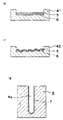
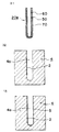
- a stabilized zirconia powder 110 is formed into a slurry, applied on a support material 100 and then sintered.
- particles of the stabilized zirconia powder 110 shrink at the time of sintering. Therefore, there have been problems in that cracks 130 are produced in the solid electrolyte film 120 formed on the support material 100, and the solid electrolyte film 120 tends to peel off.
- a principal object of this invention is to provide a solid-electrolyte fuel cell having a three-layer structure with a concave portion, which can be manufactured inexpensively and easily without producing a crack and a peeling-off in each layer.
- the present invention provides a manufacturing method for a solid-electrolyte fuel cell having a fuel-electrode (60), an air-electrode (70), and a solid-electrolyte (50) sandwiched between them, the method using a mold (4) having a concave portion (4a) and comprising the steps of:
- the electrolyte green body and the electrode green body are formed under a stable condition so that they are not cracked and peeled off. Further, the principal work is pouring and sintering of the slurry in this invention so that the manufacturing method is easy, and the mold and a device for sintering etc. are required at most so that this method is inexpensive.
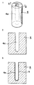
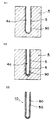
- Fig. 1 is an oblique view showing a mold for common use in each embodiment of this invention.
- Fig. 2 is a sectional view taken on a line II - II of Fig. 1.
- Fig. 3 through Fig. 6 are sectional views for each process of embodiment 1 and embodiment 11.
- Fig. 7 and Fig. 8 are sectional views for one process showing another example of the embodiment 1, respectively.
- Fig. 9 through Fig. 11 are sectional views for each process of embodiment 2.
- Fig. 12 through Fig. 15 are sectional views for each process of embodiment 3.
- Fig. 16 and Fig. 17 are sectional views for one process showing another example of the embodiment 3, respectively.
- Fig. 18 through Fig. 21 are sectional views for each process of embodiment 4.
- Fig. 25 are sectional views for each process of embodiment 5.
- Fig. 26 and Fig. 27 are sectional views for one process showing another example of the embodiment 5, respectively.
- Fig. 28 through Fig. 31 are sectional views for each process of embodiment 6.
- Fig. 32 through Fig. 36 are sectional views for each process of embodiment 7.
- Fig. 37 through Fig. 39 are sectional views for each process of embodiment 8.
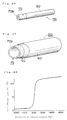
- Fig. 40 is an oblique view showing an open mold for use in embodiment 9 and embodiment 10.
- Fig. 41 through Fig. 44 are sectional views for each process of the embodiment 9.
- Fig. 45 through Fig. 47 are sectional views for each process of the embodiment 10.
- Fig. 48 is a diagram showing a relation between sintering temperatures and shrinkage factors of a conventional electrolyte green body, an electrode green body and a double-layer green body comprising the aboves in embodiment 12.
- Fig. 49 is a schematic view showing a behavior of stress at time of sintering in the embodiment 12.
- Fig. 50 is a diagram showing a relation between sintering temperatures and shrinkage factors of an electrolyte green body, an electrode green body and a double-layer green body comprising the aboves in the embodiment 12.
- Fig. 51 through Fig. 53 are sectional views for each process of embodiment 13.
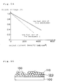
- Fig. 54 is a diagram showing a relation between output current densities and output voltages of solid-electrolyte fuel cells obtained by the embodiment 13 and the embodiment 1.
- Fig. 55 is a sectional view showing a solid-electrolyte film obtained by a conventional manufacturing method for solid-electrolyte film.
- Fig. 1 is the oblique view of a mold 4 for use in this embodiment
- Fig. 2 is the sectional view taken on the line II-II of Fig. 1.
- the mold 4 is made of a plaster which is a material having water absorptivity and includes a concave portion 4a.
- the concave portion 4a is composed of a cylindrical space having a round bottom portion.
- the manufacturing method of this embodiment is carried out in the following manner by using the mold 4.
- a slurry which comprises a zirconia powder (solid-electrolyte powder) added with yttrium oxide forming a stabilizer, water, a dispersant, a binder and an antifoamer, is prepared. That is, the slurry is prepared by utilizing the water as a solvent.
- a zirconia having a small grain size is used, and a cubic zirconia is included.
- Calcium oxide, scandium oxide, ytterbium oxide, neodymium oxide or gadolinium oxide may be used for the stabilizer.
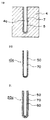
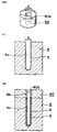
- the slurry thus prepared is poured into the concave portion 4a of the mold 4 and left as it is for a specified time so as to form an electrolyte green body 5 as shown by Fig. 3, and an excessive slurry is then removed therefrom if existing.
- the electrolyte green body 5 is formed as a film along an inside surface of the concave portion 4a.
- a slurry which comprises a nickel oxide powder (fuel-electrode powder) forming a metal oxide, the zirconia powder added with yttrium oxide forming the stabilizer, the water, the dispersant, the binder and the antifoamer, is prepared.
- a zirconia having a large grain size is used, and especially a tetragonal zirconia and a partial stabilized zirconia are included.
- the nickel oxide is used for the fuel-electrode powder, however, other metal oxides such as a cobalt oxide or other metals such as nickel, cobalt etc. may be used therefor.
- the slurry thus prepared is poured onto the electrolyte green body 5 before the electrolyte green body 5 has been dried up and left as it is for a specified time so as to form a fuel-electrode green body 6 as shown by Fig. 4, and an excessive slurry is then removed therefrom if existing.
- the fuel-electrode green body 6 is formed as a layer along a surface of the electrolyte green body 5.
- the electrolyte green body 5 and the fuel-electrode green body 6 are dried to form a double-layer green body made up by integrating the both, the mold 4 is removed therefrom, and the double-layer green body is sintered to form an electrolyte-electrode composite 10 as shown by Fig. 5.
- kind and content of the inclusion, especially the zirconia powder, of the slurry forming the electrolyte green body 5 and the fuel-electrode green body 6 are so determined that thermal expansion coefficients of the both green bodies 5 and 6 are the same level, the above-mentioned sintering can be carried out under a stable condition and the electrolyte-electrode composite 10 can be obtained without producing the crack and peeling-off.
- an outside is a solid-electrolyte film 50
- an inside is a fuel-electrode 60.
- an air-electrode 70 is to be formed on an outside of the solid-electrolyte film 50 of the electrolyte-electrode composite 10 as shown by Fig. 6.
- the air-electrode 70 is formed by using a LaMnO 3 powder (air-electrode powder) doped with strontium by means of a dipping method.
- a solid-electrolyte fuel cell 20 having a three-layer structure can thus be obtained, which is equipped with the air-electrode 70 at its outside, the fuel-electrode 60 at its inside and the solid-electrolyte film 50 sandwiched between them.
- Complex oxides having a perovskite structure other than LaMnO 3 such as LaCoO 3 and CaMnO 3 etc., for example, may be used for the air-electrode powder.
- Alkaline earth metals other than the strontium such as calcium and rare earth elements, for example, may be used for the doping substance.
- a slurry coating method and plasma spray method etc. may be used for the forming method.
- the electrolyte green body 5 and the fuel-electrode green body 6 are formed in this order by using the mold 4, and the mold 4 is then removed therefrom to form the air-electrode 70.
- the water forming the solvent of slurry is sucked in the mold 4 so that the electrolyte green body 5 and the fuel-electrode green body 6 are formed under the stable condition so as not to produce the crack and peeling-off in the processes shown by Fig. 3 and Fig. 4.
- the solid-electrolyte film 50 and the fuel-electrode 60 can be prepared easily because they are formed by the simple processes such as pouring and sintering of the slurry. Namely, the above-mentioned manufacturing method can be carried out easily.
- the mold 4 and a device for sintering are required at most so that the above-mentioned manufacturing method is inexpensive when applied.
- the zirconia having a small grain size is used for the slurry forming the electrolyte green body 5 so that the solid-electrolyte film 50 becomes dense, and the zirconia having a large grain size is used for the slurry forming the fuel-electrode green body 6 so that the fuel-electrode 60 becomes porous.
- the tetragonal zirconia or the partial stabilized zirconia is specially used for the slurry forming the fuel-electrode green body 6 so that the fuel-electrode green body 6 increases its strength when it is sintered to be formed into the fuel-electrode 60, and the fuel-electrode 60 also has a function as a support material.
- a resistance and mechanical strength of the solid-electrolyte film 50 can be controlled.
- thicknesses of the electrolyte green body 5 and the fuel-electrode green body 6 can be controlled at will by changing a time of pouring the slurry and an amount of slurry components. While, the nickel oxide added in the slurry for forming the fuel-electrode green body 6 comes in contact with a fuel to be reduced, so that it produces a function as the fuel-electrode 60.
- the solid-electrolyte fuel cell 20 prepared as described above When the solid-electrolyte fuel cell 20 prepared as described above is raised its temperature from an operation temperature 700°C up to 1,000°C, and hydrogen or carbon monoxide forming the fuel is supplied to the fuel-electrode 60 side and air is supplied to the air-electrode 70 side; the nickel oxide in the fuel-electrode 60 is reduced by the fuel. Therefore, when the fuel-electrode 60 and the air-electrode 70 of the fuel cell 20 are connected to an external circuit, oxygen supplied from the air-electrode 70 takes in electrons supplied from the external circuit to become oxide ions. The oxide ions diffuse the solid-electrolyte film 50 to reach an interface with the fuel-electrode 60.
- the plaster is used for the material of the mold 4 in the above embodiment, however, any other material may be used therefor so far as it has a water absorptivity.
- the mold 4 is one for making up the tubular battery.
- a planar type battery can be made up when a mold 41 as shown by Fig. 7 is used (not part of the invention), and a monolithic type battery can be made up when a mold 42 as shown by Fig. 8 is used.
- the slurry of the fuel-electrode green body 6 may be prepared by using the slurry of the electrolyte green body 5.
- the electrolyte green body 5 and the fuel-electrode green body 6 can be formed under the stable condition, and the crack and peeling-off can be prevented.
- the solid-electrolyte film 50 and the fuel-electrode 60 can be formed by such a simple procedure that the slurry is poured into the concave portion 4a of the mold 4 to form the electrolyte green body 5 and the fuel-electrode green body 6 which are then sintered, so that the manufacturing method can be carried out easily.
- the mold 4 and a device for sintering are required at most so that the above-mentioned manufacturing method is inexpensive when it is put in use.
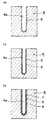
- the electrolyte green body 5 and an air-electrode green body 7 are formed in this order by using the mold 4, and the mold 4 is then removed therefrom to form the fuel-electrode 60 as shown by Fig. 9 through Fig. 11.
- the air-electrode green body 7 is formed by using the above slurry in the same way as forming the fuel-electrode green body 5 of the embodiment 1.
- the zirconia having a large grain size is used, and the tetragonal zirconia and the partial stabilized zirconia are specially included.
- the air-electrode powder other materials similar to those of the embodiment 1 may be used.
- 10a is an electrolyte-electrode composite which is formed in such a way that a double-layer green body comprising the electrolyte green body 5 and the air-electrode green body 7 is sintered after removing the mold 4 from it, and its outside is the solid-electrolyte film 50 and its inside is the air-electrode 70.
- the fuel-electrode 60 is formed at an outside of the solid-electrolyte film 50 of the electrolyte-electrode composite 10a.
- the fuel-electrode 60 is formed by using Ni-ZrO 2 cermet by means of the dipping method.
- a solid-electrolyte fuel cell 20a having a three-layer structure can thus be prepared as shown by Fig. 11, which is equipped with the fuel-electrode 60 at its outside, the air-electrode 70 at its inside and the solid-electrolyte film 50 sandwiched between them.
- Co-ZrO 2 cermet may be used for the material of the fuel-electrode 60, and the slurry coating method and spray method etc. may be used for the forming method.
- the material of the fuel-electrode 60 is not limited to the above cermet, but the metal or metal oxide similar to the embodiment 1 and the zirconia powder may be used therefor.
- the water forming the solvent of slurry is sucked in the mold 4 so that the electrolyte green body 5 and the air-electrode green body 7 are formed under the stable condition so as not to produce the crack and peeling-off.
- the solid-electrolyte film 50 and the air-electrode 70 can be prepared easily because they are formed by the simple procedure such as pouring and sintering of the slurry. Namely, the above-mentioned manufacturing method can be carried out easily.
- the zirconia having a small grain size is used for the slurry forming the electrolyte green body 5 so that the solid-electrolyte film 50 becomes dense, and the zirconia having a large grain size is used for the slurry forming the air-electrode green body 7 so that the air-electrode 70 becomes porous.
- the tetragonal zirconia or the partial stabilized zirconia is specially used for the slurry forming the air-electrode green body 7 so that the air-electrode green body 7 increases its strength when it is sintered to be formed into the air-electrode 70, and the air-electrode 70 functions also as the support material.
- thicknesses of the electrolyte green body 5 and the air-electrode green body 7 can be controlled at will by changing a time of pouring the slurry and an amount of slurry components. Functions other than aboves are similar to those of the embodiment 1, and operations of the prepared solid- electrolyte fuel cell 20a are also similar to those of the embodiment 1.
- the electrolyte green body 5 and the air-electrode green body 7 can be formed under the stable condition, and the crack and peeling-off can be prevented.
- the solid-electrolyte film 50 and the air-electrode 70 can be formed by such a simple procedure that the slurry is poured into the concave portion 4a of the mold 4 to form the electrolyte green body 5 and the air-electrode green body 7 which are then sintered, so that the manufacturing method can be carried out easily.
- the mold 4 and a device for sintering are required at most so that the above-mentioned manufacturing method is inexpensive when it is put in use.
- the electrolyte green body and the electrode (fuel-electrode and air-electrode) green body are formed in this order by using the mold 4.
- the electrode green body and the electrolyte green body are formed in this order as shown by Fig. 12 through Fig. 15.
- a slurry similar to the slurry for forming the fuel-electrode green body 6 of the embodiment 1 is prepared.
- the prepared slurry is poured into the concave portion 4a of the mold 4 and left as it is for a specified time so as to form the fuel-electrode green body 6 as shown by Fig. 12, and an excessive slurry is then removed therefrom if existing.
- the fuel-electrode green body 6 is formed as a layer along an inside surface of the concave portion 4a.
- a slurry similar to the slurry for forming the electrolyte green body 5 of the embodiment 1 is prepared.
- the slurry thus prepared is poured onto the fuel-electrode green body 6 before the fuel-electrode green body 6 has been dried up and left as it is for a specified time so as to form the electrolyte green body 5 as shown by Fig. 13, and an excessive slurry is then removed therefrom if existing.
- the electrolyte green body 5 is formed as a film along a surface of the fuel-electrode green body 6.
- the fuel-electrode green body 6 and the electrolyte green body 5 are dried to form a double-layer green body made up by integrating the both, the mold 4 is then removed therefrom, and the double-layer green body is sintered to form an electrolyte-electrode composite 10b as shown by Fig. 14.
- Fig. 14 an outside is the fuel-electrode 60, and an inside is the solid-electrolyte film 50.
- the air-electrode 70 is formed on an inside of the solid-electrolyte film 50 of the electrolyte-electrode composite 10b as shown by Fig. 15.
- the air-electrode 70 is formed by using the same material and method as those for forming the air-electrode 70 of the embodiment 1.
- a solid-electrolyte fuel cell 20b having a three-layer structure can thus be obtained, which is equipped with the fuel-electrode 60 at its outside, the air-electrode 70 at its inside and the solid-electrolyte film 50 sandwiched between them.
- the fuel-electrode green body 6 and the electrolyte green body 5 are formed in this order by using the mold 4, and the mold 4 is then removed therefrom to form the air-electrode 70.
- the above-mentioned manufacturing method also has the same function as the embodiment 1. Namely, the crack and peeling-off can be prevented. Further, this method is easy and inexpensive when it is put in use.
- the fuel-electrode 60 becomes porous and the solid-electrolyte film 50 becomes dense.
- the fuel-electrode 60 also has a function as a support material. Moreover, a resistance and mechanical strength of the solid-electrolyte film 50 can be controlled. Furthermore, thicknesses of the fuel-electrode green body 6 and the electrolyte green body 5 are also controlled at will. While, the nickel oxide added in the slurry for forming the fuel-electrode green body 6 produces a function as the fuel-electrode 60.
- the prepared solid-electrolyte fuel cell 20b also functions in the same manner as the fuel cell 20 of the embodiment 1.
- the mold 4 is used to form the tubular battery.
- a planar type battery can be obtained when a mold 41 as shown by Fig. 16 is used (not part of the invention), and a monolithic type battery can be obtained when a mold 42 as shown by Fig. 17 is used.
- the fuel-electrode green body 6 and the electrolyte green body 5 can be formed under the stable condition, and the crack and peeling-off can be prevented. Further, the fuel-electrode 60 and the solid-electrolyte film 50 can be formed by the simple process so that this method can be carried out easily. Moreover, the mold 4 and a device for sintering are required at most so that this method is inexpensive when it is put in use.
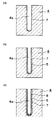
- the order of forming the electrode is different from that of the embodiment 3, and others are similar to those of the embodiment 3. Namely, in the present embodiment, the air-electrode green body 7 and the electrolyte green body 5 are formed in this order by using the mold 4, and the mold 4 is then removed therefrom to form the fuel-electrode 60 as shown by Fig. 18 through Fig. 21.
- a slurry similar to the slurry for forming the air-electrode green body 7 of the embodiment 2 is prepared.
- the prepared slurry is poured into the concave portion 4a of the mold 4 and left as it is for a specified time so as to form the air-electrode green body 7 as shown by Fig. 18, and an excessive slurry is then removed therefrom if existing.
- the air-electrode green body 7 is formed as a layer along an inside surface of the concave portion 4a.
- a slurry similar to the slurry for forming the electrolyte green body 5 of the embodiment 1 is prepared.
- the slurry thus prepared is poured onto the air-electrode green body 7 before the air-electrode green body 7 has been dried up and left as it is for a specified time so as to form an electrolyte green body 5 as shown by Fig. 19, and an excessive slurry is then removed therefrom if existing.
- the electrolyte green body 5 is formed as a film along a surface of the air-electrode green body 7.
- the air-electrode green body 7 and the electrolyte green body 5 are dried to form a double-layer green body made up by integrating the both, the mold 4 is then removed therefrom, and the double-layer green body is sintered to form an electrolyte-electrode composite 10c as shown by Fig. 20.
- Fig. 20 an outside is the air-electrode 70, and an inside is the solid-electrolyte film 50.
- the fuel-electrode 60 is formed on an inside of the solid-electrolyte film 50 of the electrolyte-electrode composite 10c as shown by Fig. 21.
- the fuel-electrode 60 is formed by using the same material and method as those for forming the fuel-electrode 60 of the embodiment 2.
- a solid-electrolyte fuel cell 20c having a three-layer structure can thus be obtained, which is equipped with the air-electrode 70 at its outside, the fuel-electrode 60 at its inside and the solid-electrolyte film 50 sandwiched between them.
- the above-mentioned manufacturing method also has the same function as the embodiment 3. Namely, the crack and peeling-off can be prevented. Further, this method is easy and inexpensive when it is put in use.
- the air-electrode 70 also has a function as the support material. Moreover, thicknesses of the air-electrode green body 7 and the electrolyte green body 5 are also controlled at will.
- the prepared solid-electrolyte fuel cell 20c also functions in the same manner as the embodiment 3.
- the air-electrode green body 7 and the electrolyte green body 5 can be formed under the stable condition, and the crack and peeling-off can be prevented. Further, the air-electrode 70 and the solid-electrolyte film 50 can be formed by the simple process so that this method can be carried out easily. Moreover, the mold 4 and a device for sintering are required at most so that this method is inexpensive when it is put in use.
- the entire of the electrolyte green body and the electrode green body are formed by using the mold 4.
- the present embodiment is different from those of the embodiment 1 through embodiment 4 in this point. Namely, in the present embodiment, the fuel-electrode green body 6, the electrolyte green body 5 and the air-electrode green body 7 are formed in this order by using the mold 4 similar to that of the embodiment 1 as shown by Fig. 22 through Fig. 25.
- a slurry similar to the slurry for forming the fuel-electrode green body 6 of the embodiment 1 is prepared.
- the prepared slurry is poured into the concave portion 4a of the mold 4 and left as it is for a specified time so as to form the fuel-electrode green body 6 as shown by Fig. 22, and an excessive slurry is then removed therefrom if existing.
- the fuel-electrode green body 6 is formed as a layer along an inside surface of the concave portion 4a.
- a slurry similar to the slurry for forming the electrolyte green body 5 of the embodiment 1 is prepared.
- the slurry thus prepared is poured onto the fuel-electrode green body 6 before the fuel-electrode green body 6 has been dried up and left as it is for a specified time so as to form an electrolyte green body 5 as shown by Fig. 23, and an excessive slurry is then removed therefrom if existing.
- the electrolyte green body 5 is formed as a film along a surface of the fuel-electrode green body 6.
- a slurry similar to the slurry for forming the air-electrode green body 7 of the embodiment 2 is prepared.
- the slurry thus prepared is poured onto the electrolyte green body 5 before the electrolyte green body 5 has been dried up and left as it is for a specified time so as to form an air-electrode green body 7 as shown by Fig. 24, and an excessive slurry is then removed therefrom if existing.
- the air-electrode green body 7 is formed as a layer along a surface of the electrolyte green body 5.
- the fuel-electrode green body 6, the electrolyte green body 5 and the air-electrode green body 7 are dried to form a three-layer green body made up by integrating the three, the mold 4 is then removed therefrom, and the three-layer green body is sintered to form a solid-electrolyte fuel cell 20d as shown by Fig. 25.
- Fig. 25 an outside is the fuel-electrode 60 and an inside is the air-electrode 70, and the solid-electrolyte film 50 is sandwiched between them.
- the above-mentioned manufacturing method also has the same function as the embodiment 1. Namely, the water forming the solvent of slurry is sucked in the mold 4 so that the fuel-electrode green body 6, the electrolyte green body 5 and the air-electrode green body 7 are formed under the stable condition so as not to produce the crack and peeling-off.
- the fuel-electrode 60, the solid-electrolyte film 50 and the air-electrode 70 can be prepared easily because they are formed by the simple process such as pouring and sintering of the slurry. Namely, the above-mentioned manufacturing method can be carried out easily.
- the mold 4 and a device for sintering are required at most so that the above-mentioned manufacturing method is inexpensive when it is put in use.
- the zirconia having a large grain size is used for the slurry forming the fuel-electrode green body 6 and the air-electrode green body 7 so that the fuel-electrode 60 and the air-electrode 70 become porous, and the zirconia having a small grain size is used for the slurry forming the electrolyte green body 5 so that the solid-electrolyte film 50 becomes dense.
- the fuel-electrode 60 and the air-electrode 70 also have a function as the support material.
- a resistance and mechanical strength of the solid-electrolyte film 50 can be controlled.
- thicknesses of the fuel-electrode green body 6, the electrolyte green body 5 and the air-electrode green body 7 can be controlled at will by changing a time of pouring the slurry and an amount of slurry components. While, the nickel oxide added in the slurry for forming the fuel-electrode green body 6 is active to produce a function as the fuel-electrode 60.
- the prepared solid-electrolyte fuel cell 20d also functions in the same manner as the fuel cell 20 of the embodiment 1.
- the mold 4 is one for making up the tubular battery in the above embodiment.
- a planar type battery can be obtained when a mold 41 as shown by Fig. 26 is used (not part of the invention), and a monolithic type battery can be obtained when a mold 42 as shown by Fig. 27 is used.
- the fuel-electrode green body 6, the electrolyte green body 5 and the air-electrode green body 7 can be formed under the stable condition, and the crack and peeling-off can be prevented.
- the fuel-electrode 60, the solid-electrolyte film 50 and the air-electrode 70 can be formed simultaneously by such a simple way that the slurry is poured into the concave portion 4a of the mold 4 to form the fuel-electrode green body 6, the electrolyte green body 5 and the air-electrode green body 7 which are then sintered, so that the manufacturing method can be carried out very easily.
- the mold 4 and a device for sintering are required at most so that the above-mentioned manufacturing method is inexpensive when it is put in use.
- the order of forming the electrode is different from that of the embodiment 5, and others are similar to those of the embodiment 5. Namely, in the present embodiment, the air-electrode green body 7, the electrolyte green body 5 and the fuel-electrode green body 6 are formed in this order by using the mold 4 as shown by Fig. 28 through Fig. 31.
- the air-electrode green body 7 (Fig. 28), the electrolyte green body 5 (Fig. 29) and the fuel-electrode green body 6 (Fig. 30) are formed in this order in the concave portion 4a of the mold 4 by using respectively a slurry similar to that used in the embodiment 5, in the same manner as the embodiment 5. They are dried to form a three-layer green body made up by integrating the three, the mold 4 is then removed therefrom, and the three-layer green body is then sintered to form a solid-electrolyte fuel cell 20e as shown by Fig. 31.
- an outside is the air-electrode 70 and an inside is the fuel-electrode 60, and the solid-electrolyte film 50 is sandwiched between them.
- the above-mentioned manufacturing method also has the same function and effect as those of the embodiment 5. Namely, the water forming the solvent of slurry is sucked in the mold 4 so that the air-electrode green body 7, the electrolyte green body 5 and the fuel-electrode green body 6 are formed under the stable condition so as not to produce the crack and peeling-off.
- the manufacturing method can also be carried out easily and inexpensively.
- other functions are the same as those of the embodiment 5.
- the prepared solid-electrolyte fuel cell 20e also functions in the same manner as the fuel cell 20 of the embodiment 1. Moreover, in this method, the crack and peeling-off can be prevented. This method can be carried out very easily and inexpensively.
- the manufacturing method of this embodiment is one which can dissolve the above problems encountered in manufacturing the solid-electrolyte fuel cell equipped with the interconnector. Namely, this manufacturing method is inexpensive and easy, and can prevent the deterioration of the battery performance.
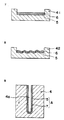
- a cellophane tape 2 forming a water resistant and water repellent member is stuck to a part (left side part of Fig. 32) of an inside surface of the concave portion 4a of the mold 4.
- a slurry similar to the slurry for forming the electrolyte green body 5 of the embodiment 1 is poured in the concave portion 4a so as to form the electrolyte green body 5 in the same manner as the embodiment 1.
- the electrolyte green body 5 is formed as a film along the inside surface of the concave portion 4a other than a part to which the cellophane tape 2 is stuck as shown by Fig. 33.
- the cellophane tape 2 is removed, and a slurry similar to the slurry for forming the fuel-electrode green body 6 of the embodiment 1 is then poured therein so as to form the fuel-electrode green body 6 in the same manner as the embodiment 1 as shown by Fig. 34.
- the fuel-electrode green body 6 is formed as a layer on the electrolyte green body 5 and along the part, to which the cellophane tape 2 was stuck, of the inside surface of the concave portion 4a. Namely, the fuel-electrode green body 6 is put under a state where it is exposed from the electrolyte green body 5 at the part to which the cellophane tape 2 was stuck.
- 6a denotes an exposed part.
- the interconnector 80 is formed in the following manner. Namely, a slurry including LaCrO 3 is applied or sprayed on a surface of the exposed part 6a of the article from which the mold 4 is removed. Thereafter, it is first sintered under an oxidizing atmosphere of about 1,000°C, and then sintered under a reducing atmosphere of about 1,300°C to 1,500°C. The sintering under an oxidizing atmosphere of about 1,000°C is carried out in order to burn out organic substances such as the dispersant and binder etc. included in the electrolyte green body 5 and the fuel-electrode green body 6.
- an outside is the solid-electrolyte film 50 and an inside is the fuel-electrode 60.
- 60a denotes a part which has been the exposed part 6a, and the interconnector 80 is formed on a surface of the part 60a.
- CoCr 2 O 4 may be used in place of LaCrO 3 .
- the air-electrode 70 is formed on an outside of the solid-electrolyte film 50 of the article shown in Fig. 35, while avoiding the interconnector 80.
- the air-electrode 70 is formed by using the same material and method as those for forming the air-electrode 70 of the embodiment 1.
- a solid-electrolyte fuel cell 20f can thus be obtained, which has a three-layer structure equipped with the air-electrode 70 at its outside, the fuel-electrode 60 at its inside and the solid-electrolyte film 50 sandwiched between them, and additionally has the interconnector 80.
- the inside fuel-electrode 60 is so devised that it can be exposed by the work using the cellophane tape 2.
- the interconnector 80 is finally sintered under the reducing atmosphere, so that it is not necessary to previously add the strontium oxide or calcium oxide excessively. This means that the interconnector 80 can be formed without using the strontium oxide or calcium oxide excessively. Therefore, the obtained fuel cell 20f is not deteriorated in its performance due to the dispersion of strontium oxide or calcium oxide.
- the water forming the solvent of slurry is sucked in the mold 4 so that the electrolyte green body 5 and the fuel-electrode green body 6 are formed under the stable condition so as not to produce the crack and peeling-off.
- the solid-electrolyte film 50, the fuel-electrode 60 and the interconnector 80 can be prepared easily by the simple process such as pouring and sintering of the slurry, so that they can be obtained easily. Namely, the above-mentioned manufacturing method can be carried out easily.
- the mold 4 and a device for sintering are required at most so that the above-mentioned manufacturing method is inexpensive when it is put in use.
- the prepared solid-electrolyte fuel cell 20f also functions in the same manner as the fuel cell 20 of the embodiment 1.
- the solid-electrolyte fuel cell 20f is equipped with the interconnector 80, the solid-electrolyte fuel cell module can be made up easily.
- the interconnector 80 is not necessarily formed by the above-mentioned method, but it may be formed by the following methods (1) and (2). Namely, the article under the state of Fig. 34 is dried and the mold 4 is then removed therefrom. (1) Thereafter, it is sintered under the oxidizing atmosphere of about 1,300°C to 1,500°C, and a material including LaCrO 3 is then sprayed on a surface of the exposed part 6a by means of the plasma spray method etc. so as to form the interconnector 80.
- the solid-electrolyte fuel cell 20f equipped with the interconnector 80 can be obtained inexpensively and easily without accompanying the deterioration of battery performance. Further, the electrolyte green body 5 and the fuel-electrode green body 6 can be formed under the stable condition so that the crack and peeling-off can be prevented.
- the manufacturing method of this embodiment is one for manufacturing a solid-electrolyte fuel cell equipped with an interconnector, and different from the embodiment 7 only in the following point. Namely, in the embodiment 7, the fuel-electrode 60 is formed at the inside and the air-electrode 70 is formed at the outside, and the fuel-electrode 60 is pulled outside so as to form the interconnector. However, in the present embodiment, the air-electrode 70 is formed at the inside and the fuel-electrode 60 is formed at the outside, and the air-electrode 70 is exposed so as to form the interconnector.
- Other points including a work and process for forming the interconnector are the same as those of the embodiment 7, except for a point that the condition of reducing atmosphere for the sintering is mild in the forming process of interconnector.
- a slurry is poured in the concave portion 4a of the mold 4 (Fig. 32) to which the cellophane tape 2 is stuck, so as to form the film-like electrolyte green body 5 (Fig. 33) along the inside surface of the concave portion 4a other than the part to which the cellophane tape 2 is stuck.
- the cellophane tape 2 is removed, and a slurry similar to the slurry for forming the air-electrode green body 7 of the embodiment 2 is then poured therein so as to form the air-electrode green body 7 in the same manner as forming the fuel-electrode green body 6 of the embodiment 7, as shown by Fig. 37.
- the air-electrode green body 7 is formed as a layer on the electrolyte green body 5 and along the part, to which the cellophane tape 2 was stuck, of the inside surface of the concave portion 4a. Namely, the air-electrode green body 7 is put under a state where it is exposed from the electrolyte green body 5 at the part to which the cellophane tape 2 was stuck.
- 7a denotes an exposed part.
- a method and material used for forming the interconnector 80 are similar to those of the embodiment 7. However, a condition of reducing atmosphere when sintering is milder than that of the embodiment 7.
- a condition of reducing atmosphere when sintering is milder than that of the embodiment 7.
- an outside is the solid-electrolyte film 50 and an inside is the air-electrode 70.
- 70a is a part which was the exposed part 7a, and the interconnector 80 is formed on a surface of the part 70a.
- the fuel-electrode 60 is formed on an outside of the solid-electrolyte film 50 of the article shown in Fig. 38, while avoiding the interconnector 80.
- the fuel-electrode 60 is formed by using the same material and method as those for forming the fuel-electrode 60 of the embodiment 2.
- a solid-electrolyte fuel cell 20g can thus be obtained, which has a three-layer structure equipped with the fuel-electrode 60 at its outside, the air-electrode 70 at its inside and the solid-electrolyte film 50 sandwiched between them, and additionally has the interconnector 80.
- the inside air-electrode 70 is so devised that it can be exposed by the work using the cellophane tape 2.
- a function of the forming method of the interconnector 80 described above is the same as that of the embodiment 7. Namely, the fuel cell 20g does not incur the deterioration of battery performance because the interconnector 80 can be formed without using the strontium oxide or calcium oxide excessively.
- the above-mentioned manufacturing method also has the same function as the embodiment 7. That is, the crack and peeling-off are not produced. In addition, this manufacturing method can be carried out easily and inexpensively. Further, the obtained solid-electrolyte fuel cell 20g operates in the same manner as the fuel cell 20a of the embodiment 2.
- the solid-electrolyte fuel cell 20g is equipped with the interconnector 80, the solid-electrolyte fuel cell module can be made up easily.
- the methods (1) and (2) of the embodiment 7 may be used for the forming method of the interconnector 80.
- the condition of reducing atmosphere should be made milder than that of the embodiment 7.
- the solid-electrolyte fuel cell 20g equipped with the interconnector 80 can be obtained inexpensively and easily without accompanying the deterioration of battery performance. Further, the electrolyte green body 5 and the air-electrode green body 7 can be formed under the stable condition so that the crack and peeling-off can be prevented.
- the manufacturing method of this embodiment is one for manufacturing a solid-electrolyte fuel cell having an exposed part of an inside electrode.
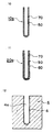
- a process for forming the exposed part using an open mold 40 shown in Fig. 40 is added to the manufacturing method of the embodiment 1, and other processes are the same as those of the embodiment 1.
- the open mold 40 is made of a plaster forming the material having a water absorptivity similar to the mold 4, formed into a cylindrical shape and has a through hole 40a.
- the through hole 40a has a shape similar to an opening of the concave portion 4a of the mold 4. That is, its lateral section is circular and has a diameter X same as that of said opening.
- the diameter of the through hole 40a may be larger than the diameter of said opening.
- the electrolyte green body 5 is formed in the concave portion 4a of the mold 4 in the same manner as the embodiment 1.
- the open mold 40 is placed on the mold 4 in such a way that the through hole 40a is set in line with the concave portion 4a as shown by Fig. 42.
- a slurry similar to the slurry for forming the fuel-electrode green body 6 of the embodiment 1 is poured not only onto the electrolyte green body 5 but into the through hole 40a, so as to form the fuel-electrode green body 6.
- 6b denotes a part which is formed on an inside surface of the through hole 40a of the fuel-electrode green body 6, and which will become the exposed part.
- the air-electrode 70 is formed only on an outside of the solid-electrolyte film 50 as shown by Fig. 44.
- Forming method and material of the air-electrode 70 are the same as those for forming the air-electrode 70 of the embodiment 1.
- a solid-electrolyte fuel cell 20h can thus be obtained, which has a three-layer structure equipped with the fuel-electrode 60 at its inside, the air-electrode 70 at its outside and the solid-electrolyte film 50 sandwiched between them, and additionally has the exposed part 60b of the fuel-electrode 60.
- this manufacturing method is one for forming the exposed part 60b of the inside fuel-electrode 60 by the work using the open mold 40.
- the water forming the solvent of slurry is sucked in the mold 4 and the open mold 40 so that the electrolyte green body 5 and the fuel-electrode green body 6 are formed under the stable condition so as not to produce the crack and peeling-off.
- the solid-electrolyte film 50, the fuel-electrode 60 and the exposed part 60b can be prepared easily by the simple process such as pouring and sintering of the slurry, so that they can be obtained easily. Namely, the above-mentioned manufacturing method can be carried out easily.
- the mold 4 and the open mold 40 and a device for sintering are required at most so that the above-mentioned manufacturing method is inexpensive when it is put in use.
- the prepared solid-electrolyte fuel cell 20h also operates in the same manner as the fuel cell 20 of the embodiment 1.
- the solid-electrolyte fuel cell 20h is equipped with the exposed part 60b, the solid-electrolyte fuel cell module can be made up easily.
- the solid-electrolyte fuel cell 20h equipped with the exposed part 60b of the inside fuel-electrode 60 can be obtained inexpensively and easily. Further, the electrolyte green body 5 and the fuel-electrode green body 6 can be formed under the stable condition so that the crack and peeling-off can be prevented.
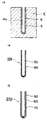
- the manufacturing method of this embodiment is one for manufacturing a solid-electrolyte fuel cell equipped with an exposed part of electrode, and different from the embodiment 9 only in the following point.
- the fuel-electrode 60 is formed at the inside and the air-electrode 70 is formed at the outside, so as to form the exposed part 60b of the fuel-electrode 60.
- the air-electrode 70 is formed at the inside and the fuel-electrode 60 is formed at the outside, and an exposed part 70b of the air-electrode 70 is formed.
- Other points including the forming process of the exposed part using the open mold 40 are the same as those of the embodiment 9.
- the electrolyte green body 5 is formed in the concave portion 4a of the mold 4 in the same manner as the embodiment 9 (Fig. 41).
- the open mold 40 is placed on the mold 4 in the same way as the embodiment 9.
- a slurry similar to the slurry for forming the air-electrode green body 7 of the embodiment 2 is poured therein in the same way as forming the fuel-electrode 6 of the embodiment 9, so as to form the air-electrode green body 7.
- 7b denotes a part which is formed on an inside surface of the through hole 40a of the air-electrode green body 7, and which will become the exposed part.
- Fig. 46 an outside is the solid-electrolyte film 50 and an inside is the air-electrode 70.
- 70b denotes an exposed part of the air-electrode 70.
- the fuel-electrode 60 is formed only on an outside of the solid-electrolyte film 50 as shown by Fig. 47.
- Forming method and material of the fuel-electrode 60 are the same as those for forming the fuel-electrode 60 of the embodiment 2.
- a solid-electrolyte fuel cell 20i can thus be obtained, which has a three-layer structure equipped with the air-electrode 70 at its inside, the fuel-electrode 60 at its outside and the solid-electrolyte film 50 sandwiched between them, and additionally has the exposed part 70b of the air-electrode 70.
- this manufacturing method is one for forming the exposed part 70b of the inside air-electrode 70 by the work using the open mold 40.
- the above-mentioned manufacturing method also has the same function as that of the embodiment 9. Namely, the crack and peeling-off are not produced. In addition, this method can be carried out easily and inexpensively.
- the prepared solid-electrolyte fuel cell 20i also functions in the same manner as the fuel cell 20a of the embodiment 2.
- the solid-electrolyte fuel cell 20i is equipped with the exposed part 70b, the solid-electrolyte fuel cell module can be made up easily.
- the solid-electrolyte fuel cell 20i equipped with the exposed part 70b of the inside air-electrode 70 can be obtained easily and inexpensively. Further, the electrolyte green body 5 and the air-electrode green body 7 can be formed under the stable condition so that the crack and peeling-off can be prevented.
- the manufacturing method of this embodiment is one in which a carbon powder or an organic powder is mixed to a slurry for forming an electrode, so as to control a shrinkage factor of green body forming the electrode and a porosity of the electrode.
- This method is applicable to any one of the above-mentioned embodiments and has similar function and effect in any one of them. A case where this method is applied to the embodiment 1 will be described hereunder with reference to Fig. 1 through Fig. 6.
- the electrolyte green body 5 is formed in the concave portion 4a of the mold 4 (Fig. 1 and Fig. 2) in the same way as the embodiment 1 (Fig. 3).
- the fuel-electrode green body 6 is then formed on the electrolyte green body 5 in the same way as the embodiment 1 (Fig. 4), and the carbon powder is to be previously mixed to the slurry used therefor in this instance.
- the slurry for forming the fuel-electrode green body 6 is composed of the nickel oxide powder forming the metal oxide (fuel-electrode powder), the carbon powder, the zirconia powder added with yttrium oxide forming the stabilizer, the water, the dispersant, the binder and the antifoamer.
- the electrolyte-electrode composite 10 is then formed in the same way as the embodiment 1 (Fig. 5), and the air-electrode 70 is formed thereafter so as to make up the solid-electrolyte fuel cell 20 (Fig. 6).
- the carbon powder is oxidized to become carbon monoxide or carbon dioxide and is released to outside. Consequently, a shrinkage factor of the fuel-electrode green body 6 will become large when a quantity of the carbon powder is large, and the former will become small when the latter is small. Further, a porosity of the fuel-electrode 60 will become large when a grain size of the carbon powder is large, and the former will become small when the latter is small.
- the shrinkage factor of the fuel-electrode green body 6 and the porosity of the fuel-electrode 60 are controlled by mixing the carbon powder to the slurry forming the fuel-electrode green body 6.
- the water forming the solvent of slurry is sucked in the mold 4 so that the electrolyte green body 5 and the fuel-electrode green body 6 are formed under the stable condition so as not to produce the crack and peeling-off.
- the shrinkage factor of the fuel-electrode green body 6 can be approximated to a shrinkage factor of the electrolyte green body 5 having a roughly constant shrinkage factor by determining the quantity of carbon powder appropriately, so that the occurrence of the crack and peeling-off can be prevented more positively.
- the porosity of the fuel-electrode 60 can also be controlled by determining the grain size of carbon powder appropriately.
- the solid-electrolyte film 50 and the fuel-electrode 60 can be formed by such a simple process that the slurry is poured into the concave portion 4a of the mold 4 so as to form the electrolyte green body 5 and the fuel-electrode green body 6 and they are sintered, so that this method is carried out easily. Furthermore, the mold 4 and a device for sintering are required at most so that the method can be carried out inexpensively.
- organic powders which are hard to be soluble in water such as a teflon powder, a vinyl chloride powder, a nylon powder and an acrylic powder etc., may be used in place of the carbon powder.
- wet methods such as a calendar roll method, a tape casting method and a slurry coating method etc. are well known as the manufacturing method for solid-electrolyte fuel cell.
- the wet method has such advantages as a comparatively good productivity and an inexpensive manufacturing cost, but it has been impossible to apply this method to the tubular type battery.
- a manufacturing process of the battery of planar type etc. by means of the wet method when each layer of electrolyte, electrode and interconnector is to be sintered, it is required to make shrinkage factors of respective layers completely equal at each temperature in the sintering process as diagrammed by Fig. 8, because its sectional structure is fundamentally one-dimensional.
- the manufacturing method of the present embodiment is one which can provide a solid-electrolyte fuel cell inexpensively and without producing the warp, crack and breakage etc., even by means of the wet method, by taking such a measure that a relation of largeness between the shrinkage factor of the electrolyte green body and the shrinkage factor of the green body for forming the electrode is reversed in the midway and at the final of sintering on the basis of a temperature change.
- the manufacturing method of this embodiment can be applied to any one of the foregoing methods, and has similar function and effect in any one of them. A case where this method is applied to the embodiment 2 will be described hereunder with reference to Fig. 1 through Fig. 3 and Fig. 9 through Fig. 11.
- the electrode green body 5 is formed in the concave portion 4a of the mold 4 (Fig. 1 and Fig. 2) in the same way as the embodiment 2 (Fig. 3).
- the air-electrode green body 7 is then formed on the electrolyte green body 5 (Fig. 9) in the same way as the embodiment 2, and the carbon powder is to be previously mixed to the slurry used therefor in this instance.
- the slurry for forming the air-electrode green body 7 is composed of the LaMnO 3 powder doped with strontium (air-electrode powder), the carbon powder, the zirconia powder added with yttrium oxide forming the stabilizer, the water, the dispersant, the binder and the antifoamer.
- the electrolyte-electrode composite 10a is formed (Fig. 10), and the fuel-electrode 60 is then formed so as to make up the solid-electrolyte fuel cell 20a (Fig. 11) in the same way as the embodiment 2.
- the temperature for sintering the electrolyte-electrode composite 10a is to be gradually raised up to 1,600°C, and the relation of largeness between the shrinkage factor of the electrolyte green body 5 and the shrinkage factor of the air-electrode green body 7 is so set as to change in the following manner on the basis of the gradually rising temperature change.
- the shrinkage factor of the outside electrolyte green body 5 is larger than the shrinkage factor of the inside air-electrode green body 7 in the midway of sintering, the former is equal to or smaller than the latter at the final of sintering, and the temperature at the final of sintering is in a range of 1,200°C to 1,600°C.
- the setting of above change in shrinkage factor is done by appropriately setting a quantity of carbon powder, and the function of carbon powder is the same as that of the embodiment 11.
- the shrinkage factor is varied in the midway and at the final of sintering as above-mentioned so that the warp, crack and breakage etc. are not produced.
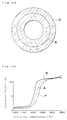
- a double-layer green body A comprising the electrolyte green body 5 and the air-electrode green body 7 of Fig. 9 has a two-dimensional structure as shown by Fig. 49. Accordingly, in case when the shrinkage factor of the outside electrolyte green body 5 is larger than the shrinkage factor of the inside air-electrode green body 7, a tensile stress is applied in directions of arrows. Since the stress is uniformly applied in a circumferential direction, the crack and breakage are hard to be produced in the process of sintering. However, when the temperature is lowered with this state kept as it is, the crack and breakage will be produced during cooling due to the tensile stress in the directions of arrows.
- the temperature at the final of sintering is in a range of 1,200°C to 1,600°C; the porosity of the air-electrode 70, the density of the solid-electrolyte film 50 and the strength of the electrolyte-electrode composite 10a are satisfied respectively.
- Fig. 50 shows changes in shrinkage factors of the double-layer green body A, the electrolyte green body 5 and the air-electrode green body 7, respectively.
- the shrinkage factor of the electrolyte green body 5 does not concur with the shrinkage factor of the air-electrode green body 7, and they differ each other by about 10% at maximum.
- the warp, crack and breakage were positively prevented by the above-mentioned manufacturing method. Accordingly, the above manufacturing method can be carried out fairly easily as compared with the conventional method where they should be made equal completely.
- the water forming the solvent of slurry is sucked in the mold 4 so that the electrolyte green body 5 and the air-electrode green body 7 can be formed under the stable condition, and the crack and peeling-off can be prevented.
- the shrinkage factor of the outside electrolyte green body 5 is made larger than the shrinkage factor of the inside air-electrode green body 7 in the midway of sintering, and the former is made equal to or smaller than the latter at the final of sintering, so that the warp, crack and breakage etc. can be prevented positively.
- this method can be carried out fairly easily and inexpensively as compared with the conventional method in which they should be made completely equal.
- the manufacturing method of this embodiment is one in which a porous high-molecular film is previously installed on an inside surface of the mold so as to prevent characteristics of the obtained solid-electrolyte fuel cell from being deteriorated due to ingress of components included in the mold.
- This method is applicable to any one of the foregoing methods, and has similar functions and effects in any one of them. A case where this method is applied to the embodiment 1 will be described hereunder.
- a porous high-molecular film 90 is installed on an inside surface of the concave portion 4a of the mold 4 made of a plaster as shown by Fig. 51, and the electrolyte green body 5 is formed on it in the same way as the embodiment 1.
- a material comprising a cellulose-based resin, a teflon-based resin, a polyvinyl-based resin, a nylon-based resin or polyamide-based resin, is used for the high-molecular film 90.
- the fuel-electrode green body 6 is formed on the electrolyte green body 5 in the same way as the embodiment 1.
- the electrolyte-electrode composite 10 is then formed to make up the air-electrode 70 at an outside of the electrolyte green body 5, so as to make up the solid-electrolyte fuel cell 20 (Fig. 6), as shown by Fig. 53.
- calcium sulfate is included in the plaster composing the mold 4.
- the porous high-molecular film 90 is previously installed on the inside surface of the concave portion 4a of the mold 4 as shown by Fig. 51, a movement of the calcium sulfate from the mold 4 to the electrolyte green body 5 and the fuel-electrode green body 6 is prevented by the high-molecular film 90 physically.
- the calcium sulfate do not enter the electrolyte green body 5 and the fuel-electrode green body 6, so that the characteristics of the solid-electrolyte film 50 and the fuel-electrode 60 are prevented from being deteriorated. Further, other components in the mold 4 are also physically prevented from moving by the high-molecular film 90, so that affects of the other components on the characteristics are also avoided.
- Fig. 54 shows the result. As seen from Fig. 54, the fuel cell of the present embodiment has a better relation between the output current density and the output voltage.
- the characteristics of the prepared solid-electrolyte fuel cell 20 can be prevented from being deteriorated due to the components in the mold 4, especially the calcium sulfate, so that the solid-electrolyte fuel cell 20 having a high performance can be obtained.
- Other functions and effects are the same as those of the embodiment 1.
- the water is used for the solvent of slurry.
- an organic solvent is used in the manufacturing method of this embodiment.
- the manufacturing method of this embodiment can be applied to any method of the foregoing embodiments by converting the water into the organic solvent, and has similar functions and effects in any one of them. A case where this method is applied to the embodiment 3 will be described hereunder with reference to Fig. 1, Fig. 3, and Fig. 12 through Fig. 15.
- ethyl alcohol is used for the organic solvent, and a material having a property to suck the ethyl alcohol, i.e. a plaster, is used for the mold 4 (Fig. 1 and Fig. 2).
- a slurry which comprises the nickel oxide powder (fuel-electrode powder) forming the metal oxide, the zirconia powder added with yttrium oxide forming the stabilizer, the ethyl alcohol, the dispersant, the binder and the antifoamer, is prepared. That is, the slurry is prepared by using the ethyl alcohol as the solvent. The prepared slurry is then poured into the concave portion 4a of the mold 4 in the same way as the embodiment 3, so as to form the fuel-electrode green body 6 as shown by Fig. 12.
- a slurry similar to the slurry for forming the electrolyte green body 5 of the embodiment 3 is poured onto the fuel-electrode green body 6 before the fuel-electrode green body 6 has been dried up in the same way as the embodiment 3, so as to form the electrolyte green body 5 as shown by Fig. 13.
- the fuel-electrode green body 6 and the electrolyte green body 5 are dried to form a double-layer green body made up by integrating the both, the mold 4 is then removed therefrom, and the double-layer green body is sintered to form an electrolyte-electrode composite 10b as shown by Fig. 14.
- an outside is the fuel-electrode 60 and an inside is the solid-electrolyte film 50.
- the air-electrode 70 is formed on an inside of the solid-electrolyte film 50 of the electrolyte-electrode composite 10b as shown by Fig. 15.
- the solvent of slurry is the ethyl alcohol, so that the fuel-electrode green body 6 and the electrolyte green body 5 are dried in a short time. Further, since the material sucked by the mold 4 is the ethyl alcohol, the mold 4 is also dried in a short time. Therefore, the time required for drying in the manufacturing processes is considerably shortened, and the manufacturing time is in its turn fairly shortened.
- the present manufacturing method is able to shorten the time for drying, so that it can shorten the manufacturing time in its turn.
- Other functions and effects are the same as those of the embodiment 3.
- the used carbon powder and organic powder are the same as those of the embodiment 11.
- This invention is usable to a solid-electrolyte fuel cell having a three-layer structure and equipped with a fuel-electrode, an air-electrode and a solid-electrolyte sandwiched between them, and to an easy and inexpensive manufacture of a fuel cell having a high performance.
Landscapes
- Life Sciences & Earth Sciences (AREA)
- Engineering & Computer Science (AREA)
- Manufacturing & Machinery (AREA)
- Sustainable Development (AREA)
- Sustainable Energy (AREA)
- Chemical & Material Sciences (AREA)
- Chemical Kinetics & Catalysis (AREA)
- Electrochemistry (AREA)
- General Chemical & Material Sciences (AREA)
- Fuel Cell (AREA)
Description
thereby to form a multi-layer green body having a concave portion corresponding to that of the mold, and then subsequently,
wherein the concave portion (4a) of the mold (4) is formed of a material that draws off the solvent from the electrolyte and electrode slurries when they are in the concave portion (4a) of the mold (4) to form the respective green bodies (5,6,7).
Claims (26)
- A manufacturing method for a solid-electrolyte fuel cell having a fuel-electrode (60), an air-electrode (70), and a solid-electrolyte (50) sandwiched between them, the method using a mold (4) having a concave portion (4a) and comprising the steps of:(a) pouring an electrolyte slurry into the concave portion (4a) of the mold (4) to form an electrolyte green body (5), the electrolyte slurry comprising a solid-electrolyte powder and solvent; and(b) pouring an electrode slurry into the concave portion (4a) of the mold (4) to form a fuel-electrode green body (6) or an air-electrode green body (7), the electrode slurry comprising an electrode powder and solvent;
thereby to form a multi-layer green body having a concave portion corresponding to that of the mold, and then subsequently,(c) removing the multi-layer green body from the mold (4) and sintering it;
wherein the concave portion (4a) of the mold (4) is formed of a material that draws off the solvent from the electrolyte and electrode slurries when they are in the concave portion (4a) of the mold (4) to form the respective green bodies (5,6,7). - A method according to claim 1, whereinthe electrolyte slurry is poured into the mold (4) before the electrode slurry and the electrode slurry is poured onto the electrolyte green body (5) formed in the mold (4),sintering the multi-layer green body forms an electrolyte-electrode composite (10,10a), andthe other said electrode(60,70), is formed on the electrolyte side of the sintered composite (10,10a).
- A method according to claim 1, wherein
the electrode slurry is poured into the mold (4) before the electrolyte slurry and the electrolyte slurry is poured onto the electrode green body (6,7) formed in the mold (4),sintering the multi-layer green body forms an electrolyte-electrode composite (10b,10c), andthe other said electrode (60,70) is formed on the electrolyte side of the sintered composite (10b,10c). - A method according to claim 2 or 3, wherein a fuel-electrode green body (6) is formed in step (b) and the air-electrode (70) is formed in the step following sintering.
- A method according to claim 2 or 3, wherein an air-electrode green body (7) is formed in step (b) and the fuel-electrode (60) is formed in the step following sintering.
- A method according to claim 2 or 3, wherein the fuel-electrode (60) is formed using Ni-ZrO2 cermet or Co-ZrO2 cermet.
- A method according to claim 2, wherein:before pouring the electrolyte slurry into the mold (4) a water resistant, water repellent member (2) is installed on a part of an inside surface of the concave portion (4a) of the mold (4),the water resistant, water repellent member (2) being removed before pouring the electrode slurry onto the electrolyte green body (5), thereby to provide an outwardly exposed part (6a,7a) of the electrode in the multi-layer green body formed,an interconnector part (80) is formed on the exposed part (60a,70a) of the electrode after removal of green body from the mold, andthe further electrode (60,70) is formed on the electrolyte side of the composite avoiding the interconnector part (80).
- A method according to claim 7, wherein to form the interconnector part (80) a slurry comprising LaCrO3 or CoCr2O4 is applied or sprayed onto the exposed part (6a,7a) of the electrode green body (6,7) and then sintered.
- A method according to claim 2, wherein:before pouring the electrode slurry into the mold (4) a second, open mold (40) having a through-hole (40a) of the same shape as and equal or larger in size than an opening ("x") of the concave portion (4a) of the mold (4), is placed on the mold (4) with the through-hole (40a) aligned with the concave portion (4a),with the open mold (40) in place, the electrode slurry is poured into the concave portion (4a) up to and occupying the through-hole (40a) to provide an exposed part (6b,7b) of the electrode, protruding from the electrolyte (5), in the multi-layer green body formed, andfollowing sintering to form the electrolyte-electrode composite (10h,10i) the other electrode (60,70) is formed on the electrolyte side of the composite (10h,10i) avoiding the exposed part (6b,7b).
- A method according to claim 1, wherein in step (b)the electrode slurry is poured into the mold (4) before the electrolyte slurry to form a fuel-electrode green body (6) or an air-electrode green body (7),the electrolyte slurry is poured onto the electrode green body (6,7) thus formed to form an electrolyte green body (5), andthe green body (6,7) for the other of the fuel-electrode and air-electrode is formed by pouring a second electrode slurry onto the electrolyte green body (5) in the concave portion (4a) of the mold (4), the slurry comprising an electrode powder and solvent.
- A method according to claim 10, wherein the fuel-electrode green body (6) is formed before forming the air-electrode green body (7).
- A method according to claim 10, wherein the air-electrode green body (7) is formed before to forming the fuel-electrode green body (6).
- A method according to any one of claims 2, 3 and 10, wherein the solvent is water, and the mold (4) comprises a material having water absorptivity.
- A method according to any one of claims 2, 3 and 10, wherein the solvent is an organic solvent which is apt to be evaporated more quickly than water, and the mold (4) comprises a material having a property to draw off the organic solvent.
- A method according to claim 14, wherein the organic solvent is ethyl alcohol.
- A method according to any one of claims 2, 3 and 10, wherein a relationship between the magnitude of the shrinkage factors of the electrolyte green body (5) and the fuel-electrode green body (6) or air-electrode green body (7) is reversed midway during and in the final part of sintering on the basis of a temperature change gradually rising up to a specified value during sintering.
- A method according to claim 16, wherein the final sintering temperature is in the range 1,200°C to 1,600°C.
- A method according to any one of claims 2, 3 and 10, wherein a carbon powder or an organic powder which is substantially insoluble in said solvent is mixed to the electrode slurry including the fuel-electrode powder or the air-electrode powder, and the sintering step is carried out in an atmosphere including oxygen.
- A method according to claim 18, wherein the organic powder is one or more selected from teflon powder, vinyl chloride powder, nylon powder and acrylic powder.
- A method according to any one of claims 2, 3 and 10, further comprising applying a porous high-molecular film to an inside surface of the concave portion (4a) of said mold (4) before pouring the slurries.
- A method according to claim 20, wherein the porous high-molecular film comprises a cellulose-based resin, a teflon-based resin, a polyvinyl-based resin, a nylon-based resin or a polyamide-based resin.
- A method according to any one of claims 2, 3 and 10, wherein the solid-electrolyte powder is a zirconia powder with a stabilizer and comprises stabilized zirconia, cubic zirconia, tetragonal zirconia, partially stabilized zirconia, or a mixture of any of these.
- A method according to claim 22, wherein the stabilizer is yttrium oxide, calcium oxide, scandium oxide, ytterbium oxide, neodymium oxide or gadolinium oxide.
- A method according to any one of claims 2, 3 or 10, wherein the fuel-electrode powder is a powder of metal or metal oxide, the metal being nickel or cobalt, and the metal oxide being a nickel oxide or a cobalt oxide.
- A method according to any one of claims 2, 3 and 10, wherein the air-electrode powder is a powder of complex oxide of perovskite, and the complex oxide is LaMnO3, LaCoO3, or CaMnO3 added with rare earth metals or alkaline earth metals.
- A method according to any one of the preceding claims in which the fuel cell is tubular.
Applications Claiming Priority (55)
| Application Number | Priority Date | Filing Date | Title |
|---|---|---|---|
| JP2409997A JP3050328B2 (en) | 1990-12-10 | 1990-12-10 | Method for manufacturing solid electrolyte fuel cell |
| JP40999790 | 1990-12-10 | ||
| JP409997/90 | 1990-12-10 | ||
| JP41095990 | 1990-12-14 | ||
| JP2410959A JPH04218264A (en) | 1990-12-14 | 1990-12-14 | Manufacturing method of solid electrolyte fuel cell |
| JP410959/90 | 1990-12-14 | ||
| JP41140290 | 1990-12-17 | ||
| JP411402/90 | 1990-12-17 | ||
| JP41140290 | 1990-12-17 | ||
| JP2412014A JPH04218265A (en) | 1990-12-18 | 1990-12-18 | Manufacture of solid electrolyte fuel cell |
| JP412014/90 | 1990-12-18 | ||
| JP41201490 | 1990-12-18 | ||
| JP29539/91 | 1991-01-29 | ||
| JP2953991 | 1991-01-29 | ||
| JP3029539A JP3050331B2 (en) | 1991-01-29 | 1991-01-29 | Method for manufacturing solid electrolyte fuel cell |
| JP3029540A JPH04289666A (en) | 1991-01-29 | 1991-01-29 | Manufacture of solid electrolyte fuel battery |
| JP29540/91 | 1991-01-29 | ||
| JP2954091 | 1991-01-29 | ||
| JP3044367A JPH04315769A (en) | 1991-02-15 | 1991-02-15 | Manufacture of solid electrolyte fuel cell |
| JP44367/91 | 1991-02-15 | ||
| JP4436791 | 1991-02-15 | ||
| JP5936991 | 1991-02-28 | ||
| JP59369/91 | 1991-02-28 | ||
| JP59368/91 | 1991-02-28 | ||
| JP3059369A JPH04289669A (en) | 1991-02-28 | 1991-02-28 | Manufacture of solid electrolyte fuel battery |
| JP3059368A JPH04289668A (en) | 1991-02-28 | 1991-02-28 | Method for manufacturing solid electrolyte fuel cells |
| JP5936891 | 1991-02-28 | ||
| JP3072352A JPH04289670A (en) | 1991-03-11 | 1991-03-11 | Manufacture of electrode-solid electrolyte complex |
| JP7235291 | 1991-03-11 | ||
| JP72352/91 | 1991-03-11 | ||
| JP83261/91 | 1991-03-23 | ||
| JP3083261A JPH04322061A (en) | 1991-03-23 | 1991-03-23 | Manufacture of solid electrolytic fuel cell |
| JP83260/91 | 1991-03-23 | ||
| JP8326191 | 1991-03-23 | ||
| JP3083260A JPH05144450A (en) | 1991-03-23 | 1991-03-23 | Manufacture of fuel cell with solid electrolyte |
| JP8326091 | 1991-03-23 | ||
| JP3208685A JPH0529008A (en) | 1991-07-24 | 1991-07-24 | Manufacture of solid electrolyte fuel cell |
| JP20868491 | 1991-07-24 | ||
| JP208684/91 | 1991-07-24 | ||
| JP20868591 | 1991-07-24 | ||
| JP208685/91 | 1991-07-24 | ||
| JP3208684A JPH0529007A (en) | 1991-07-24 | 1991-07-24 | Manufacture of solid electrolyte fuel cell |
| JP240466/91 | 1991-08-26 | ||
| JP3240466A JPH0554899A (en) | 1991-08-26 | 1991-08-26 | Manufacture of electrode/solid electrolyte composite material |
| JP24046691 | 1991-08-26 | ||
| JP270055/91 | 1991-09-20 | ||
| JP27005591 | 1991-09-20 | ||
| JP3270055A JPH0582143A (en) | 1991-09-20 | 1991-09-20 | Manufacture of solid electrolyte fuel cell |
| JP284031/91 | 1991-10-03 | ||
| JP28403191 | 1991-10-03 | ||
| JP3284031A JPH05101841A (en) | 1991-10-03 | 1991-10-03 | Manufacture of solid electrolytic fuel cell |
| JP28914891 | 1991-10-07 | ||
| JP289148/91 | 1991-10-07 | ||
| JP3289148A JPH0629031A (en) | 1990-12-17 | 1991-10-07 | Manufacture of solid electrolyte fuel cell |
| PCT/JP1991/001701 WO1992010862A1 (en) | 1990-12-10 | 1991-12-09 | Method for manufacturing solid-state electrolytic fuel cell |
Publications (3)
| Publication Number | Publication Date |
|---|---|
| EP0514552A1 EP0514552A1 (en) | 1992-11-25 |
| EP0514552A4 EP0514552A4 (en) | 1993-08-04 |
| EP0514552B1 true EP0514552B1 (en) | 2000-05-17 |
Family
ID=27586116
Family Applications (1)
| Application Number | Title | Priority Date | Filing Date |
|---|---|---|---|
| EP92900502A Expired - Lifetime EP0514552B1 (en) | 1990-12-10 | 1991-12-09 | Method for manufacturing solid-state electrolytic fuel cell |
Country Status (3)
| Country | Link |
|---|---|
| US (1) | US5290323A (en) |
| EP (1) | EP0514552B1 (en) |
| WO (1) | WO1992010862A1 (en) |
Families Citing this family (34)
| Publication number | Priority date | Publication date | Assignee | Title |
|---|---|---|---|---|
| US5631099A (en) * | 1995-09-21 | 1997-05-20 | Hockaday; Robert G. | Surface replica fuel cell |
| US5759712A (en) * | 1997-01-06 | 1998-06-02 | Hockaday; Robert G. | Surface replica fuel cell for micro fuel cell electrical power pack |
| US6296910B1 (en) * | 1997-05-29 | 2001-10-02 | Imperial College Of Science, Technology & Medicine | Film or coating deposition on a substrate |
| US6096449A (en) | 1997-11-20 | 2000-08-01 | Avista Labs | Fuel cell and method for controlling same |
| US6030718A (en) | 1997-11-20 | 2000-02-29 | Avista Corporation | Proton exchange membrane fuel cell power system |
| USRE39556E1 (en) * | 1997-11-20 | 2007-04-10 | Relion, Inc. | Fuel cell and method for controlling same |
| WO1999045607A1 (en) * | 1998-03-03 | 1999-09-10 | Celltech Power, Llc | A carbon-oxygen electricity-generating unit |
| US6326097B1 (en) | 1998-12-10 | 2001-12-04 | Manhattan Scientifics, Inc. | Micro-fuel cell power devices |
| US6194095B1 (en) | 1998-12-15 | 2001-02-27 | Robert G. Hockaday | Non-bipolar fuel cell stack configuration |
| CA2406312A1 (en) | 2000-04-18 | 2001-10-25 | Celltech Power, Inc. | An electrochemical device and methods for energy conversion |
| US7326480B2 (en) * | 2000-05-17 | 2008-02-05 | Relion, Inc. | Fuel cell power system and method of controlling a fuel cell power system |
| US6468682B1 (en) | 2000-05-17 | 2002-10-22 | Avista Laboratories, Inc. | Ion exchange membrane fuel cell |
| US8007954B2 (en) | 2000-11-09 | 2011-08-30 | The Trustees Of The University Of Pennsylvania | Use of sulfur-containing fuels for direct oxidation fuel cells |
| WO2003001617A2 (en) * | 2001-06-25 | 2003-01-03 | Celltech Power, Inc. | Electrode layer arrangements in an electrochemical device |
| US7943270B2 (en) * | 2003-06-10 | 2011-05-17 | Celltech Power Llc | Electrochemical device configurations |
| WO2004112175A2 (en) * | 2003-06-10 | 2004-12-23 | Celltech Power, Inc. | Oxidation facilitator |
| US20060040167A1 (en) * | 2003-10-16 | 2006-02-23 | Celltech Power, Inc. | Components for electrochemical devices including multi-unit device arrangements |
| US7531261B2 (en) * | 2003-06-30 | 2009-05-12 | Corning Incorporated | Textured electrolyte sheet for solid oxide fuel cell |
| US7275019B2 (en) * | 2005-05-17 | 2007-09-25 | Dell Products L.P. | System and method for information handling system thermal diagnostics |
| US7820332B2 (en) | 2006-09-27 | 2010-10-26 | Corning Incorporated | Electrolyte sheet with regions of different compositions and fuel cell device including such |
| US10615444B2 (en) | 2006-10-18 | 2020-04-07 | Bloom Energy Corporation | Anode with high redox stability |
| US8748056B2 (en) | 2006-10-18 | 2014-06-10 | Bloom Energy Corporation | Anode with remarkable stability under conditions of extreme fuel starvation |
| US20080199751A1 (en) * | 2007-02-20 | 2008-08-21 | Commonwealth Scientific And Industrial Research Organisation | Bipolar plate for an air breathing fuel cell stack |
| US20080254336A1 (en) * | 2007-04-13 | 2008-10-16 | Bloom Energy Corporation | Composite anode showing low performance loss with time |
| US20080261099A1 (en) * | 2007-04-13 | 2008-10-23 | Bloom Energy Corporation | Heterogeneous ceramic composite SOFC electrolyte |
| US8617763B2 (en) * | 2009-08-12 | 2013-12-31 | Bloom Energy Corporation | Internal reforming anode for solid oxide fuel cells |
| AU2011209829C1 (en) | 2010-01-26 | 2016-09-01 | Bloom Energy Corporation | Phase stable doped zirconia electrolyte compositions with low degradation |
| US8440362B2 (en) | 2010-09-24 | 2013-05-14 | Bloom Energy Corporation | Fuel cell mechanical components |
| CN104798237B (en) | 2012-11-20 | 2018-12-14 | 博隆能源股份有限公司 | Zirconia electrolyte composition stabilized by doped scandia |
| US9755263B2 (en) | 2013-03-15 | 2017-09-05 | Bloom Energy Corporation | Fuel cell mechanical components |
| US10651496B2 (en) | 2015-03-06 | 2020-05-12 | Bloom Energy Corporation | Modular pad for a fuel cell system |
| WO2018236834A1 (en) * | 2017-06-19 | 2018-12-27 | Massachusetts Institute Of Technology | Solid oxide battery |
| US12266835B2 (en) | 2017-08-28 | 2025-04-01 | Bloom Energy Corporation | SOFC including redox-tolerant anode electrode and method of making the same |
| US10680251B2 (en) | 2017-08-28 | 2020-06-09 | Bloom Energy Corporation | SOFC including redox-tolerant anode electrode and system including the same |
Family Cites Families (14)
| Publication number | Priority date | Publication date | Assignee | Title |
|---|---|---|---|---|
| DE1179852B (en) * | 1961-08-30 | 1964-10-15 | Zirconium Corp Of America | Process for producing a refractory object |
| NL300914A (en) * | 1962-11-23 | 1900-01-01 | ||
| US3377203A (en) * | 1963-12-20 | 1968-04-09 | Univ Ernst Moritz Arndt | Method of producing fuel cells with solid electrolytes and ceramic oxide electrode layers |
| US3843400A (en) * | 1972-09-18 | 1974-10-22 | Westinghouse Electric Corp | Solid electrolyte cell |
| JPS6036369A (en) * | 1983-08-09 | 1985-02-25 | 日本碍子株式会社 | Ceramic manufacture |
| JPS62502790A (en) * | 1985-03-15 | 1987-10-22 | アムペツクス コ−ポレ−シヨン | Apparatus and method for generating rotating clock video wipes |
| US4596750A (en) * | 1985-03-15 | 1986-06-24 | Westinghouse Electric Corp. | Support tube for high temperature solid electrolyte electrochemical cell |
| JPS62268063A (en) * | 1986-05-14 | 1987-11-20 | Mitsubishi Heavy Ind Ltd | Solid electrolyte manufacturing method |
| JPS647475A (en) * | 1987-06-30 | 1989-01-11 | Mitsubishi Heavy Ind Ltd | Manufacture of flat type solid electrolyte fuel cell |
| JP2622261B2 (en) * | 1987-10-05 | 1997-06-18 | 三菱重工業株式会社 | Method for manufacturing solid electrolyte fuel cell |
| JPH01110904A (en) * | 1987-10-26 | 1989-04-27 | Isuzu Motors Ltd | Method for slip-casting molded ceramic |
| US4957673A (en) * | 1988-02-01 | 1990-09-18 | California Institute Of Technology | Multilayer ceramic oxide solid electrolyte for fuel cells and electrolysis cells and method for fabrication thereof |
| JPH0381972A (en) * | 1989-08-24 | 1991-04-08 | Toppan Printing Co Ltd | Manufacture of solid electrolyte for fuel cell |
| JPH03101065A (en) * | 1989-09-13 | 1991-04-25 | Toppan Printing Co Ltd | Solid electrolyte for fuel cell and manufacture thereof |
-
1991
- 1991-12-09 WO PCT/JP1991/001701 patent/WO1992010862A1/en not_active Ceased
- 1991-12-09 EP EP92900502A patent/EP0514552B1/en not_active Expired - Lifetime
- 1991-12-09 US US07/915,699 patent/US5290323A/en not_active Expired - Fee Related
Also Published As
| Publication number | Publication date |
|---|---|
| EP0514552A1 (en) | 1992-11-25 |
| US5290323A (en) | 1994-03-01 |
| WO1992010862A1 (en) | 1992-06-25 |
| EP0514552A4 (en) | 1993-08-04 |
Similar Documents
| Publication | Publication Date | Title |
|---|---|---|
| EP0514552B1 (en) | Method for manufacturing solid-state electrolytic fuel cell | |
| Zhan et al. | A reduced temperature solid oxide fuel cell with nanostructured anodes | |
| US5358735A (en) | Method for manufacturing solid oxide film and method for manufacturing solid oxide fuel cell using the solid oxide film | |
| US20060024547A1 (en) | Anode supported sofc with an electrode multifunctional layer | |
| JP3502012B2 (en) | Solid oxide fuel cell and method of manufacturing the same | |
| Liu et al. | Fabrication and characterization of micro-tubular cathode-supported SOFC for intermediate temperature operation | |
| CA2000917A1 (en) | Modified cermet fuel electrodes for solid oxide electrochemical cells | |
| KR102436926B1 (en) | Electrochemical element, cell for solid oxide fuel cell, and preparation methods for these | |
| US5277995A (en) | Electrode and method of interconnection sintering on an electrode of an electrochemical cell | |
| Liu et al. | Tailoring the pore structure of cathode supports for improving the electrochemical performance of solid oxide fuel cells | |
| US8999607B2 (en) | Manufacturing method of solid oxide fuel cell, and manufacturing method of compact of divided member of the cell | |
| KR102719579B1 (en) | Method for manufacturing electrochemical element and electrochemical element | |
| JP2848551B2 (en) | Method for producing electrolyte membrane for solid oxide fuel cell | |
| JPH11126617A (en) | Solid oxide fuel cell and method of manufacturing the same | |
| JP3050328B2 (en) | Method for manufacturing solid electrolyte fuel cell | |
| JP3451627B2 (en) | Method for manufacturing solid electrolyte fuel cell | |
| KR100813420B1 (en) | Manufacturing method of electrolyte membrane for solid oxide fuel cell | |
| CN113330612B (en) | Electrochemical cell | |
| JPH04315769A (en) | Manufacture of solid electrolyte fuel cell | |
| JPH05198305A (en) | Manufacture of solid electrolyte fuel cell | |
| JP7105772B2 (en) | Anode for fuel cell and method of making same | |
| JPH04289668A (en) | Method for manufacturing solid electrolyte fuel cells | |
| JPH04322061A (en) | Manufacture of solid electrolytic fuel cell | |
| JPH0529007A (en) | Manufacture of solid electrolyte fuel cell | |
| Dokiya et al. | Overview of Planar SOFC Development at NCLI |
Legal Events
| Date | Code | Title | Description |
|---|---|---|---|
| PUAI | Public reference made under article 153(3) epc to a published international application that has entered the european phase |
Free format text: ORIGINAL CODE: 0009012 |
|
| AK | Designated contracting states |
Kind code of ref document: A1 Designated state(s): AT BE CH DE DK ES FR GB GR IT LI LU MC NL SE |
|
| RBV | Designated contracting states (corrected) |
Designated state(s): DE FR GB NL |
|
| 17P | Request for examination filed |
Effective date: 19921029 |
|
| A4 | Supplementary search report drawn up and despatched |
Effective date: 19930611 |
|
| AK | Designated contracting states |
Kind code of ref document: A4 Designated state(s): AT BE CH DE DK ES FR GB GR IT LI LU MC NL SE |
|
| RAP1 | Party data changed (applicant data changed or rights of an application transferred) |
Owner name: YUASA CORPORATION |
|
| 17Q | First examination report despatched |
Effective date: 19960222 |
|
| GRAG | Despatch of communication of intention to grant |
Free format text: ORIGINAL CODE: EPIDOS AGRA |
|
| GRAG | Despatch of communication of intention to grant |
Free format text: ORIGINAL CODE: EPIDOS AGRA |
|
| GRAH | Despatch of communication of intention to grant a patent |
Free format text: ORIGINAL CODE: EPIDOS IGRA |
|
| GRAG | Despatch of communication of intention to grant |
Free format text: ORIGINAL CODE: EPIDOS AGRA |
|
| GRAH | Despatch of communication of intention to grant a patent |
Free format text: ORIGINAL CODE: EPIDOS IGRA |
|
| GRAH | Despatch of communication of intention to grant a patent |
Free format text: ORIGINAL CODE: EPIDOS IGRA |
|
| GRAA | (expected) grant |
Free format text: ORIGINAL CODE: 0009210 |
|
| AK | Designated contracting states |
Kind code of ref document: B1 Designated state(s): DE FR GB NL |
|
| REF | Corresponds to: |
Ref document number: 69132207 Country of ref document: DE Date of ref document: 20000621 |
|
| ET | Fr: translation filed | ||
| PLBE | No opposition filed within time limit |
Free format text: ORIGINAL CODE: 0009261 |
|
| STAA | Information on the status of an ep patent application or granted ep patent |
Free format text: STATUS: NO OPPOSITION FILED WITHIN TIME LIMIT |
|
| 26N | No opposition filed | ||
| PGFP | Annual fee paid to national office [announced via postgrant information from national office to epo] |
Ref country code: GB Payment date: 20011212 Year of fee payment: 11 Ref country code: FR Payment date: 20011212 Year of fee payment: 11 |
|
| PGFP | Annual fee paid to national office [announced via postgrant information from national office to epo] |
Ref country code: NL Payment date: 20011228 Year of fee payment: 11 |
|
| REG | Reference to a national code |
Ref country code: GB Ref legal event code: IF02 |
|
| PGFP | Annual fee paid to national office [announced via postgrant information from national office to epo] |
Ref country code: DE Payment date: 20020109 Year of fee payment: 11 |
|
| PG25 | Lapsed in a contracting state [announced via postgrant information from national office to epo] |
Ref country code: GB Free format text: LAPSE BECAUSE OF NON-PAYMENT OF DUE FEES Effective date: 20021209 |
|
| PG25 | Lapsed in a contracting state [announced via postgrant information from national office to epo] |
Ref country code: NL Free format text: LAPSE BECAUSE OF NON-PAYMENT OF DUE FEES Effective date: 20030701 Ref country code: DE Free format text: LAPSE BECAUSE OF NON-PAYMENT OF DUE FEES Effective date: 20030701 |
|
| GBPC | Gb: european patent ceased through non-payment of renewal fee | ||
| NLV4 | Nl: lapsed or anulled due to non-payment of the annual fee |
Effective date: 20030701 |
|
| PG25 | Lapsed in a contracting state [announced via postgrant information from national office to epo] |
Ref country code: FR Free format text: LAPSE BECAUSE OF NON-PAYMENT OF DUE FEES Effective date: 20030901 |
|
| REG | Reference to a national code |
Ref country code: FR Ref legal event code: ST |