EP0513616B1 - Extruder head for applying coatings of polymeric material to semifinished products of elongated cylindrical conformation - Google Patents
Extruder head for applying coatings of polymeric material to semifinished products of elongated cylindrical conformation Download PDFInfo
- Publication number
- EP0513616B1 EP0513616B1 EP92107518A EP92107518A EP0513616B1 EP 0513616 B1 EP0513616 B1 EP 0513616B1 EP 92107518 A EP92107518 A EP 92107518A EP 92107518 A EP92107518 A EP 92107518A EP 0513616 B1 EP0513616 B1 EP 0513616B1
- Authority
- EP
- European Patent Office
- Prior art keywords
- centering element
- extruder head
- eccentricity
- central duct
- outflow port
- Prior art date
- Legal status (The legal status is an assumption and is not a legal conclusion. Google has not performed a legal analysis and makes no representation as to the accuracy of the status listed.)
- Expired - Lifetime
Links
- 239000011265 semifinished product Substances 0.000 title claims abstract description 35
- 239000000463 material Substances 0.000 title claims description 27
- 238000000576 coating method Methods 0.000 title claims description 24
- 239000000203 mixture Substances 0.000 claims abstract description 29
- 239000011248 coating agent Substances 0.000 claims description 21
- 238000006073 displacement reaction Methods 0.000 claims description 7
- 239000004033 plastic Substances 0.000 claims description 6
- 230000001747 exhibiting effect Effects 0.000 claims description 3
- 229940090441 infed Drugs 0.000 claims description 3
- 238000001514 detection method Methods 0.000 claims description 2
- 239000010410 layer Substances 0.000 description 15
- 230000000875 corresponding effect Effects 0.000 description 6
- 239000000047 product Substances 0.000 description 6
- 230000015572 biosynthetic process Effects 0.000 description 4
- 239000004020 conductor Substances 0.000 description 4
- 230000000694 effects Effects 0.000 description 2
- 238000003908 quality control method Methods 0.000 description 2
- 230000007704 transition Effects 0.000 description 2
- 230000004075 alteration Effects 0.000 description 1
- 239000011247 coating layer Substances 0.000 description 1
- 230000006835 compression Effects 0.000 description 1
- 238000007906 compression Methods 0.000 description 1
- 230000002596 correlated effect Effects 0.000 description 1
- 230000007547 defect Effects 0.000 description 1
- 230000001419 dependent effect Effects 0.000 description 1
- 230000001066 destructive effect Effects 0.000 description 1
- 238000010586 diagram Methods 0.000 description 1
- 239000013536 elastomeric material Substances 0.000 description 1
- 238000001125 extrusion Methods 0.000 description 1
- 238000010438 heat treatment Methods 0.000 description 1
- 239000011810 insulating material Substances 0.000 description 1
- 238000004519 manufacturing process Methods 0.000 description 1
- 230000004048 modification Effects 0.000 description 1
- 238000012986 modification Methods 0.000 description 1
- 230000003472 neutralizing effect Effects 0.000 description 1
- 230000002035 prolonged effect Effects 0.000 description 1
- 229920001169 thermoplastic Polymers 0.000 description 1
- 239000012815 thermoplastic material Substances 0.000 description 1
- 239000004416 thermosoftening plastic Substances 0.000 description 1
Images


Classifications
-
- H—ELECTRICITY
- H01—ELECTRIC ELEMENTS
- H01B—CABLES; CONDUCTORS; INSULATORS; SELECTION OF MATERIALS FOR THEIR CONDUCTIVE, INSULATING OR DIELECTRIC PROPERTIES
- H01B13/00—Apparatus or processes specially adapted for manufacturing conductors or cables
- H01B13/06—Insulating conductors or cables
- H01B13/14—Insulating conductors or cables by extrusion
- H01B13/143—Insulating conductors or cables by extrusion with a special opening of the extrusion head
-
- B—PERFORMING OPERATIONS; TRANSPORTING
- B29—WORKING OF PLASTICS; WORKING OF SUBSTANCES IN A PLASTIC STATE IN GENERAL
- B29C—SHAPING OR JOINING OF PLASTICS; SHAPING OF MATERIAL IN A PLASTIC STATE, NOT OTHERWISE PROVIDED FOR; AFTER-TREATMENT OF THE SHAPED PRODUCTS, e.g. REPAIRING
- B29C48/00—Extrusion moulding, i.e. expressing the moulding material through a die or nozzle which imparts the desired form; Apparatus therefor
- B29C48/03—Extrusion moulding, i.e. expressing the moulding material through a die or nozzle which imparts the desired form; Apparatus therefor characterised by the shape of the extruded material at extrusion
- B29C48/06—Rod-shaped
-
- B—PERFORMING OPERATIONS; TRANSPORTING
- B29—WORKING OF PLASTICS; WORKING OF SUBSTANCES IN A PLASTIC STATE IN GENERAL
- B29C—SHAPING OR JOINING OF PLASTICS; SHAPING OF MATERIAL IN A PLASTIC STATE, NOT OTHERWISE PROVIDED FOR; AFTER-TREATMENT OF THE SHAPED PRODUCTS, e.g. REPAIRING
- B29C48/00—Extrusion moulding, i.e. expressing the moulding material through a die or nozzle which imparts the desired form; Apparatus therefor
- B29C48/03—Extrusion moulding, i.e. expressing the moulding material through a die or nozzle which imparts the desired form; Apparatus therefor characterised by the shape of the extruded material at extrusion
- B29C48/09—Articles with cross-sections having partially or fully enclosed cavities, e.g. pipes or channels
-
- B—PERFORMING OPERATIONS; TRANSPORTING
- B29—WORKING OF PLASTICS; WORKING OF SUBSTANCES IN A PLASTIC STATE IN GENERAL
- B29C—SHAPING OR JOINING OF PLASTICS; SHAPING OF MATERIAL IN A PLASTIC STATE, NOT OTHERWISE PROVIDED FOR; AFTER-TREATMENT OF THE SHAPED PRODUCTS, e.g. REPAIRING
- B29C48/00—Extrusion moulding, i.e. expressing the moulding material through a die or nozzle which imparts the desired form; Apparatus therefor
- B29C48/25—Component parts, details or accessories; Auxiliary operations
- B29C48/30—Extrusion nozzles or dies
- B29C48/32—Extrusion nozzles or dies with annular openings, e.g. for forming tubular articles
- B29C48/325—Extrusion nozzles or dies with annular openings, e.g. for forming tubular articles being adjustable, i.e. having adjustable exit sections
- B29C48/327—Extrusion nozzles or dies with annular openings, e.g. for forming tubular articles being adjustable, i.e. having adjustable exit sections with centering means
-
- B—PERFORMING OPERATIONS; TRANSPORTING
- B29—WORKING OF PLASTICS; WORKING OF SUBSTANCES IN A PLASTIC STATE IN GENERAL
- B29C—SHAPING OR JOINING OF PLASTICS; SHAPING OF MATERIAL IN A PLASTIC STATE, NOT OTHERWISE PROVIDED FOR; AFTER-TREATMENT OF THE SHAPED PRODUCTS, e.g. REPAIRING
- B29C48/00—Extrusion moulding, i.e. expressing the moulding material through a die or nozzle which imparts the desired form; Apparatus therefor
- B29C48/25—Component parts, details or accessories; Auxiliary operations
- B29C48/30—Extrusion nozzles or dies
- B29C48/32—Extrusion nozzles or dies with annular openings, e.g. for forming tubular articles
- B29C48/34—Cross-head annular extrusion nozzles, i.e. for simultaneously receiving moulding material and the preform to be coated
-
- B—PERFORMING OPERATIONS; TRANSPORTING
- B29—WORKING OF PLASTICS; WORKING OF SUBSTANCES IN A PLASTIC STATE IN GENERAL
- B29C—SHAPING OR JOINING OF PLASTICS; SHAPING OF MATERIAL IN A PLASTIC STATE, NOT OTHERWISE PROVIDED FOR; AFTER-TREATMENT OF THE SHAPED PRODUCTS, e.g. REPAIRING
- B29C48/00—Extrusion moulding, i.e. expressing the moulding material through a die or nozzle which imparts the desired form; Apparatus therefor
- B29C48/25—Component parts, details or accessories; Auxiliary operations
- B29C48/92—Measuring, controlling or regulating
-
- B—PERFORMING OPERATIONS; TRANSPORTING
- B29—WORKING OF PLASTICS; WORKING OF SUBSTANCES IN A PLASTIC STATE IN GENERAL
- B29C—SHAPING OR JOINING OF PLASTICS; SHAPING OF MATERIAL IN A PLASTIC STATE, NOT OTHERWISE PROVIDED FOR; AFTER-TREATMENT OF THE SHAPED PRODUCTS, e.g. REPAIRING
- B29C2948/00—Indexing scheme relating to extrusion moulding
- B29C2948/92—Measuring, controlling or regulating
- B29C2948/92009—Measured parameter
- B29C2948/92114—Dimensions
- B29C2948/92152—Thickness
-
- B—PERFORMING OPERATIONS; TRANSPORTING
- B29—WORKING OF PLASTICS; WORKING OF SUBSTANCES IN A PLASTIC STATE IN GENERAL
- B29C—SHAPING OR JOINING OF PLASTICS; SHAPING OF MATERIAL IN A PLASTIC STATE, NOT OTHERWISE PROVIDED FOR; AFTER-TREATMENT OF THE SHAPED PRODUCTS, e.g. REPAIRING
- B29C2948/00—Indexing scheme relating to extrusion moulding
- B29C2948/92—Measuring, controlling or regulating
- B29C2948/92323—Location or phase of measurement
- B29C2948/92438—Conveying, transporting or storage of articles
-
- B—PERFORMING OPERATIONS; TRANSPORTING
- B29—WORKING OF PLASTICS; WORKING OF SUBSTANCES IN A PLASTIC STATE IN GENERAL
- B29C—SHAPING OR JOINING OF PLASTICS; SHAPING OF MATERIAL IN A PLASTIC STATE, NOT OTHERWISE PROVIDED FOR; AFTER-TREATMENT OF THE SHAPED PRODUCTS, e.g. REPAIRING
- B29C2948/00—Indexing scheme relating to extrusion moulding
- B29C2948/92—Measuring, controlling or regulating
- B29C2948/92504—Controlled parameter
- B29C2948/92571—Position, e.g. linear or angular
-
- B—PERFORMING OPERATIONS; TRANSPORTING
- B29—WORKING OF PLASTICS; WORKING OF SUBSTANCES IN A PLASTIC STATE IN GENERAL
- B29C—SHAPING OR JOINING OF PLASTICS; SHAPING OF MATERIAL IN A PLASTIC STATE, NOT OTHERWISE PROVIDED FOR; AFTER-TREATMENT OF THE SHAPED PRODUCTS, e.g. REPAIRING
- B29C2948/00—Indexing scheme relating to extrusion moulding
- B29C2948/92—Measuring, controlling or regulating
- B29C2948/92504—Controlled parameter
- B29C2948/92609—Dimensions
- B29C2948/92647—Thickness
-
- B—PERFORMING OPERATIONS; TRANSPORTING
- B29—WORKING OF PLASTICS; WORKING OF SUBSTANCES IN A PLASTIC STATE IN GENERAL
- B29C—SHAPING OR JOINING OF PLASTICS; SHAPING OF MATERIAL IN A PLASTIC STATE, NOT OTHERWISE PROVIDED FOR; AFTER-TREATMENT OF THE SHAPED PRODUCTS, e.g. REPAIRING
- B29C2948/00—Indexing scheme relating to extrusion moulding
- B29C2948/92—Measuring, controlling or regulating
- B29C2948/92504—Controlled parameter
- B29C2948/92609—Dimensions
- B29C2948/92666—Distortion, shrinkage, dilatation, swell or warpage
-
- B—PERFORMING OPERATIONS; TRANSPORTING
- B29—WORKING OF PLASTICS; WORKING OF SUBSTANCES IN A PLASTIC STATE IN GENERAL
- B29C—SHAPING OR JOINING OF PLASTICS; SHAPING OF MATERIAL IN A PLASTIC STATE, NOT OTHERWISE PROVIDED FOR; AFTER-TREATMENT OF THE SHAPED PRODUCTS, e.g. REPAIRING
- B29C2948/00—Indexing scheme relating to extrusion moulding
- B29C2948/92—Measuring, controlling or regulating
- B29C2948/92819—Location or phase of control
- B29C2948/92857—Extrusion unit
- B29C2948/92904—Die; Nozzle zone
-
- B—PERFORMING OPERATIONS; TRANSPORTING
- B29—WORKING OF PLASTICS; WORKING OF SUBSTANCES IN A PLASTIC STATE IN GENERAL
- B29C—SHAPING OR JOINING OF PLASTICS; SHAPING OF MATERIAL IN A PLASTIC STATE, NOT OTHERWISE PROVIDED FOR; AFTER-TREATMENT OF THE SHAPED PRODUCTS, e.g. REPAIRING
- B29C2948/00—Indexing scheme relating to extrusion moulding
- B29C2948/92—Measuring, controlling or regulating
- B29C2948/92819—Location or phase of control
- B29C2948/92933—Conveying, transporting or storage of articles
Definitions
- the present invention relates to an extruder head for applying coating mixtures to semifinished products of elongated cylindrical conformation.
- the present invention is concerned with an extruder head for extruders of the type used for example for coating electric conductors with insulating material and in general coating any continuously fed article of cylindrical form with elastomeric or thermoplastic material according to the preamble of claim 1.
- Electrical conductors either in the form of individual wires or of multiwired cables, must be coated with polymeric, thermoplastic or elastomeric materials such as PVC, EPR and the like, adapted to perform electric insulating functions and/or protection functions.
- polymeric, thermoplastic or elastomeric materials such as PVC, EPR and the like, adapted to perform electric insulating functions and/or protection functions.
- the extruder head comprises a female mould and a male mould housed in a fixed supporting body, which at the outlet define the annular outflow port through which the material flows thereby covering the semifinished product coming out of the central duct provided in the male mould.
- the coating applied to the semifinished product is required to be coaxial with the semifinished product.
- the coating must have a substantially constant thickness.
- some of the factors that can originate the undesired eccentricity of the coating are represented by possible temperature differences in different regions of the moulds, differences in the path really travelled by the polymeric material for reaching the annular port, in combination with rheologic features of the material being used, and others.
- the polymeric materials in the plastic state always have a degree of elasticity, it results that when by effect of the above factors the coating material encounters various resistances to its moving forward along the path travelled for reaching and going past the outflow port, it undergoes several local elastic compressions that are given back in the form of expansions at the outlet from the outflow port for the formation of the coating layer.
- the product coming from the extruder head is submitted to targeted quality controls aiming at checking the homogeneity in thickness of the applied coating mixture.
- these quality controls can be carried out both periodically by cutting the product in order to check the geometrical and size features of the coating, and continuously by means of appropriate non-destructive sensors capable of identifying possible thickness differences in the coating by directly acting on the outside of the product being worked, downstream of the extruder head.
- the female mould is substantially held in place by a plurality of circumferentially-distributed adjusting screws, generally in the number of four, acting radially between the supporting body and the female mould.
- adjusting screws By acting on said adjusting screws the positioning of the female mould relative to the male mould can be modified by displacing the female mould according to a plane perpendicular to the central duct axis, as far as a the outflow port defined between the moulds is given a certain degree of eccentricity capable of neutralising the eccentricity that would be otherwise produced on the applied coating.
- the male mould is essentially linked to the supporting body by a ball joint in concentric relation with the central duct. Adjusting screws enable the male mould to be swung around the rotational centre defined by the ball joint, so as to geometrically modify the outflow port as previously said.
- an extruder head for applying a coating of polymeric material to semifinished products of elongated cylindrical conformation comprising:
- the first hole of truncated conical form exibited by the centering element has an oblique axis relative to the rotational axis of the centering element itself forming an angle equal to the angle of incidence of the centering element axis on the central duct axis.
- said female mould in addition comprises an intermediate collar rotatably carrying said centering element, said intermediate collar being in turn engaged to the supporting body in a rotating manner in coaxial relation with the central duct for arranging an eccentricity plane containing the axes of the central duct and the outflow port in the desired orientation.
- said intermediate collar exhibits a second hole of truncated conical form, coaxial with the central duct, partly defining said shaped housing and extending in a continuity relationship between the hollow feed gap and the first hole of truncated conical form formed in the centering element.
- the displacement of the outflow port from the centering position to the maximum-eccentricity position corresponds to an angular rotation through 180° of the centering element about its own axis of rotation.
- the maximum eccentricity of the outflow port relative to the axis of the central duct is at least equal to 20% of the thickness of said layer of material applied to the semifinished product.
- the angle of incidence of the rotational axis of the centering element to the axis of the central duct is in the range of 1° to 5°.
- reading means is provided between the centering element and the intermediate collar for identifying the rotational axis of the centering element relative to the intermediate collar and, in connection therewith, the eccentricity value of the outflow port relative to the axis of the central duct and the orientation of the eccentricity plane containing the axes of the outflow port and the central duct, with respect to the body.
- said reading means comprises one series of indices and a second series of indices reproduced on the centering element and the intermediate collar respectively and circumferentially distributed following an increasing order in respectively opposite directions, according to respective arcs of circumferences of angular amplitude equal to half the angular travel of the centering element corresponding to the displacement of the outflow port from the centered position to the maximum eccentricity position, each index of the first series being arranged to be selectively brought into register with a corresponding index belonging to the second series in order to indicate the value of said eccentricity.
- the alignment position of the corresponding indices of the first and second series identifies the orientation of said plane of eccentricity.
- auxiliary reading means adapted to indicate the angular orientation of the collar itself relative to said supporting body.
- said auxiliary reading means comprises at least a goniometric scale reproduced on the supporting body and at least a reference index reproduced on the intermediate collar.
- the extruder head of the invention comprises remote control actuator means, operatively connected to said centering element through respective driving means designed to cause an angular rotation of the latter, of amplitude to be established in advance, about its own axis.
- the extruder head comprises remote control actuator means operatively connected to said intermediate collar through respective driving means adapted to cause an angular rotation of the latter of amplitude to be established in advance.
- the extruder head comprises first and second actuator means acting on the centering element and intermediate collar respectively through respective driving means operatively connected to detection and control means for establishing the thickness of the mixture layer applied to the semifinished product, located downstream of the outflow port and adapted to operate said first and second actuator means in order to cause respective angular rotations of the centering element and intermediate collar about their respective axes of rotation, correspondingly to the thickness eccentricity values of the mixture layer and to the lying of said eccentricity detected by the control means itself.
- an extruder head for applying coating mixtures to semifinished products of elongated cylindrical configuration in accordance with the present invention has been generally identified by reference numeral 1.
- the extruder head conventionally comprises a supporting body 2 of substantially cylindrical configuration, fastened to an extruder 3 (Fig. 3) which in known manner is designed to work one or more components previously introduced into a charging hopper 4, so as to obtain a mixture of polymeric material in the plastic state which is injected into the extruder head 1.
- a male mould 5 longitudinally passed through by a central duct 6 along which a semifinished product 7 is worked.
- the semifinished product 7 consisting for example of an electric conductor, a wire, a cord, a cable or another article of substantially cylindrical configuration, is continuously infed by means not shown as known per se and not of importance to the ends of the invention, so that it emerges from the central duct 6 at an outlet end 5a of the male mould 5 substantially of truncated conical form.
- a hollow feed gap Formed between the male mould 5 and the supporting body 2 is a hollow feed gap into which the above mixture in a plastic state is introduced through means not shown as known per se and conventional connecting the gap to the extruder 3.
- the mixture being constantly pushed since it is acted upon by the extruder 3, continuously flows towards the outlet end 5a of the male mould 5.
- a female mould 9 conformed such as to form a shaped housing 10 disposed about the outlet end 5a of the male mould 5 in order to define, together with the outlet end itself, an outflow port 11 for the mixture.
- This outflow port 11 therefore communicates with the hollow feed gap 8 and surrounds the semifinished product 7 emerging from the male mould 5.
- the mixture coming from the feed gap 8 will be therefore applied in the form of a continuous layer 7a to the semifinished product 7 emerging from the male mould 5.
- the female mould 9 comprises at least a centering element 12 provided with a first hole of truncated conical form 12a defining the outflow port 11 and at least part of the shaped housing 10.
- the centering element 12 can rotate according to an oblique and incident axis "y” through an angle " ⁇ " of predetermined amplitude, relative to the axis of the first frustoconical hole 12a and to the axis "x" of the central duct 6, and therefore of the semifinished product 7.
- the first frustoconical hole 12a is made so as to be coaxial with the central duct 6 at a predetermined rotational position of the centering element 12.
- the geometric shape of the first frustoconical hole 12a is substantially defined by a frustum of cone of oblique axis relative to the rotational axis "y" of the centering element 12 and coincident with axis "x" in said predetermined position.
- the shape of the outflow port 11 is modified from a centered configuration relative to the central duct 6, as shown in Fig. 1, to a configuration in which the duct 6 is eccentric, as shown in Fig. 2.
- the angular rotation performed by the centering element 12 in order to modify the configuration of the outflow port 11 between the above mentioned two end positions conveniently equals 180°.
- the outflow port 11 will take different eccentricity values included between a zero value and a maximum value, to be selectively used depending upon requirements.
- the centering element 12 is mounted with no possibility of axial movement within an intermediate collar 13 in turn axially locked in the supporting body 2 and rotating in coaxial relation with the central duct 6.
- the intermediate collar 13 exhibits a second hole 13a of truncated conical form, coaxial with the central duct 6 and defining part of said shaped housing 10.
- the second frustoconical hole 13a substantially extends in a continuity relationship between the hollow feed gap 8 and the frustoconical hole 12a formed in the centering element 12.
- the centering element 12 is provided to be rotated about its axis "y" so as to give the outflow port 11 an eccentricity of predetermined value, in correlation with the eccentricity that can be undesirably exhibited by the mixture layer 7a relative to the semifinished product 7 so as to carry out the compensation thereof. Therefore, by acting on the intermediate collar 13 it is possible to bring the plane in which the desired eccentricity of the outflow port 11 has been achieved to the appropriate angular position, for example a position having opposite way with respect to the eccentricity of the mixture layer 7a, so that the last mentioned eccentricity will be neutralised on the product coming out of the extruder head 1, as shown in Fig. 2.
- the rotations of the centering element 12 and intermediate collar 13 can be controlled by hand or with the aid of driving members 9a, 12b, consisting for example of lever tools diagrammatically shown in Fig. 2, adapted to be engaged with the centering element 12 and collar 13.
- the manual control can be achieved with the aid of mechanical driving members engaged to the supporting body 2 and intermediate collar 13 respectively and in engagement with corresponding paired driving members carried by the intermediate collar itself and centering member 12 respectively.
- These mechanical driving members for example can consist of gearing, worm screws or the like and are therefore adapted to enable the remote eccentricity adjustment.
- the eccentricity adjustment can be executed manually, by identifying the occurrence of a defect in the extruded coating and, based on the manually detected data, piloting the appropriate rotations of tools 9a, 12b or the mechanical driving members adapted for the purpose.
- first and second actuator means 14, 15 consisting for example of servomotors adapted to move said mechanical driving members, causing the desired rotations.
- Said actuator means 14, 15 can be driven either directly or automatically through control means 17 acting on the product being worked downstream of the extruder head 1, with reference to the advancing direction of the semifinished product 7.
- control means 17 through respective sensing members not described or shown as known and conventional, continuously detects the thickness of the coating mixture 7a applied to the semifinished product 7.
- An electronic control box 18 receives the signals coming from the control means 17 and causes the operation of the actuator means 14, 15 so as to modify the eccentricity of the outflow port 11 by the angular rotation consequently imparted to the centering element 12 and/or the intermediate collar 13, in order to correct the anomaly found in the product being worked.
- Figs. 4 to 9 in order to facilitate the manual adjustment or enable the automatic adjustment to be duly checked, provision may be also made for reading means 19 to be disposed between the centering element 12 and the intermediate collar 13, which will enable the immediate identification of the eccentricity of the outflow port 11 relative to the axis "x" of the central duct 6, as well as the orientation of the eccentricity plane containing the axes "z" "x" of the outflow port and central duct.
- This reading means 19 comprises one series of indices 19a, denoted by O, A, B, C, D, reproduced on the centering element 12, and a second series of indices 19b denoted by O', A', B', C', D', formed on the intermediate collar 13.
- a given eccentricity value of the outflow port 11 corresponds to each of the indices of the first series O, A, B, C, D, and second series O', A', B', C', D', individually correlated with each other.
- letters A, B, C, D, A', B', C', D' can be replaced with the real eccentricity values corresponding to them, expressed under metric or percent form.
- Indices of the first series O, A, B, C, D and second series O', A', B', C', D' are shown in an increasing order in respectively opposite directions and according to respective arcs of circumferences spaced apart by the same distance on an angular amplitude equal to half the angular travel carried out by the centering element 12 for bringing the outflow port 11 from the centered position to the maximum-eccentricity position.
- the plane in which indices B, B' belonging to the first and second series respectively, in coincidence with each other, have been disposed is advantageously also coincident with the plane in which the eccentricity containing axis "z" of the outflow port 11 and axis "x" of the central duct 6 has been determined.
- auxiliary reading means 20 can also be provided.
- Said means is formed between the supporting body 2 and the intermediate collar 13 and is designed to point out the angular orientation of the collar relative to said supporting body constituting a fixed reference.
- This auxiliary reading means 20 comprises a goniometric scale 20a circumferentially reproduced on the supporting body 2 and one or more read indices 20b reproduced on the intermediate collar 13.
- the rotational axis "y" of the centering element has been provided to be incident on axis "x" of the central duct 6 in the transition plane between the first and second frustoconical holes 12a, 13a, according to an angle " ⁇ " of about 2°, in order to give the outflow port 11 a maximum eccentricity of 2 mm.
- the maximum eccentricity to be given to the outflow port 11 is preferably provided to be at least equal to 20% of the thickness of the mixture layer 7a to be applied to the semifinished product, and angle " ⁇ " is provided to have a value included between 1° and 5°.
- angles of angle " ⁇ " lower than the stated range could require too great a length value of the female mould 9.
- values of angle " ⁇ " higher than stated could involve, under some angular positions, important deflections to the mixture flow between the surfaces of hole 13a and hole 12a.
- Each of said additional moulds is comprised of a centering element and an intermediate collar in the same manner as above described so that the eccentricity of all mixture layers applied to the semifinished product can be corrected.
- the extruder head in question enables the geometrical conformation of the mixture layer or layers to be adjusted in a practical and precise manner, while keeping a particularly simple mechanical structure.
- the present invention enables the conformation of the female mould to be suitably modified without involving the formation of sharp localized deflections in the path travelled by the mixture, which would bring about, as a result, undesired stagnation or slowing-down areas in the material flow.
- the extruder head in question keeps a very simple structure, adapted to be easily dismantled for servicing purposes and for carrying out the control and/or replacement of the components thereof and that it lends itself both to a remote control and to an automatic control of the eccentricity, during the production.
Landscapes
- Engineering & Computer Science (AREA)
- Mechanical Engineering (AREA)
- Manufacturing & Machinery (AREA)
- Extrusion Moulding Of Plastics Or The Like (AREA)
- Coating Apparatus (AREA)
Abstract
Description
- The present invention relates to an extruder head for applying coating mixtures to semifinished products of elongated cylindrical conformation.
- In greater detail, the present invention is concerned with an extruder head for extruders of the type used for example for coating electric conductors with insulating material and in general coating any continuously fed article of cylindrical form with elastomeric or thermoplastic material according to the preamble of
claim 1. - Electrical conductors, either in the form of individual wires or of multiwired cables, must be coated with polymeric, thermoplastic or elastomeric materials such as PVC, EPR and the like, adapted to perform electric insulating functions and/or protection functions.
- The application of these coatings is carried out by continuous extrusion, with the aid of extruder heads exhibiting a central duct along which there is the passage of the wire or the cable being worked which is then coated with the mixture in the plastic state coming from an outflow port of annular form substantially coaxial with the central duct. In greater detail, the extruder head comprises a female mould and a male mould housed in a fixed supporting body, which at the outlet define the annular outflow port through which the material flows thereby covering the semifinished product coming out of the central duct provided in the male mould.
- In most cases the coating applied to the semifinished product is required to be coaxial with the semifinished product. In other words, the coating must have a substantially constant thickness. For the purpose it is necessary to previously calculate the delivery sections of the mixture along the path travelled by it for reaching the outflow port, so as to have a constant and regular material delivery over the whole section of the outflow port.
- It has however been found that as a result of different factors that cannot be either foreseen or quantified, the possibility arises that the coating applied to the semifinished product will not be perfectly coaxial with the semifinished product.
- By way of example, some of the factors that can originate the undesired eccentricity of the coating are represented by possible temperature differences in different regions of the moulds, differences in the path really travelled by the polymeric material for reaching the annular port, in combination with rheologic features of the material being used, and others.
- For example, since the polymeric materials in the plastic state always have a degree of elasticity, it results that when by effect of the above factors the coating material encounters various resistances to its moving forward along the path travelled for reaching and going past the outflow port, it undergoes several local elastic compressions that are given back in the form of expansions at the outlet from the outflow port for the formation of the coating layer.
- In order to eliminate these problems, the product coming from the extruder head is submitted to targeted quality controls aiming at checking the homogeneity in thickness of the applied coating mixture. In greater detail, these quality controls can be carried out both periodically by cutting the product in order to check the geometrical and size features of the coating, and continuously by means of appropriate non-destructive sensors capable of identifying possible thickness differences in the coating by directly acting on the outside of the product being worked, downstream of the extruder head.
- Should an eccentricity of the coating applied to the conductor be detected following said controls, it is possible to intervene by causing the outflow port of the material from the extruder head to be offset relative to the central duct passed through by the semifinished product, so as to compensate for the found anomaly as far as the coating is brought to coaxiality conditions.
- For the purpose in the known art provision is made for adjusting the outflow port eccentricity by different technical solutions.
- According to one of these solutions the female mould is substantially held in place by a plurality of circumferentially-distributed adjusting screws, generally in the number of four, acting radially between the supporting body and the female mould. By acting on said adjusting screws the positioning of the female mould relative to the male mould can be modified by displacing the female mould according to a plane perpendicular to the central duct axis, as far as a the outflow port defined between the moulds is given a certain degree of eccentricity capable of neutralising the eccentricity that would be otherwise produced on the applied coating.
- Another known solution for displacing the female mould in a plane perpendicular to the central duct his is described in the German patent application DE-A-3619005 wherein said displacement is obtained by means of a couple of eccentric rings whose axes are parallel to one another and parallel to the central duct axis.
- According to another known technical solution, the male mould is essentially linked to the supporting body by a ball joint in concentric relation with the central duct. Adjusting screws enable the male mould to be swung around the rotational centre defined by the ball joint, so as to geometrically modify the outflow port as previously said.
- In accordance with the present invention it has been found that by forming the shaped housing of the female mould with a centering element rotating according to an oblique and incident axis relative to the axis of the central duct, it is possible to geometrically modify the outflow port depending upon requirements, by rotating the centering element without giving rise to the formation, along the extruded-material travel, of discontinuities and/or obstructions to the flow to such an extend that stagnations or slowing downs of the material within the extruder head may occur.
- In particular,in accordance with the invention, an extruder head is provided for applying a coating of polymeric material to semifinished products of elongated cylindrical conformation comprising:
- a fixed supporting body (2);
- a male mould (5) fastened to the inside of the supporting body (2), having a tapered end portion (5a) substantially of truncated conical form and a central duct (6) susceptible of being longitudinally passed through by a continuously-infed cylindrical semifinished product (7) emerging from the end of said end portion (5a) of the male mould (5);
- connecting means for connection to an extruder (3), designed to feed at least a polymeric material in the plastic state into a hollow feed gap (8) formed between the supporting body (2) and the male mould (5);
- at least a female mould (9) provided with a shaped housing (10) disposed around the end portion (5a) of the male mould (5), defining, in cooperation therewith, a passage channel for said material, said channel communicating with the feed gap (8) and forming an annular outflow port (11) at the opposite end thereof, through which a layer of material (7a) is applied to the semifinished product (7),
said female mould (9) comprising at least a centering element (12) exhibiting one hole (12a) of truncated conical form at least partly defining said shaped housing (10), and defining said outflow port (11) at the end thereof,
characterized in that said centering element (12) is rotatable around an axis (y) which is oblique and is incident to the axis (x) of said central duct (6) so as to bring the outflow port (11) to a position to be selected, between a centered position and a maximum-eccentricity position relative to said central duct (6). - In greater detail, the first hole of truncated conical form exibited by the centering element has an oblique axis relative to the rotational axis of the centering element itself forming an angle equal to the angle of incidence of the centering element axis on the central duct axis.
- In a preferred embodiment said female mould in addition comprises an intermediate collar rotatably carrying said centering element, said intermediate collar being in turn engaged to the supporting body in a rotating manner in coaxial relation with the central duct for arranging an eccentricity plane containing the axes of the central duct and the outflow port in the desired orientation.
- In particular said intermediate collar exhibits a second hole of truncated conical form, coaxial with the central duct, partly defining said shaped housing and extending in a continuity relationship between the hollow feed gap and the first hole of truncated conical form formed in the centering element.
- Preferably the displacement of the outflow port from the centering position to the maximum-eccentricity position corresponds to an angular rotation through 180° of the centering element about its own axis of rotation.
- In a particular embodiment of the extruder head of the invention the maximum eccentricity of the outflow port relative to the axis of the central duct is at least equal to 20% of the thickness of said layer of material applied to the semifinished product.
- Preferably the angle of incidence of the rotational axis of the centering element to the axis of the central duct is in the range of 1° to 5°.
- In a preferred embodiment reading means is provided between the centering element and the intermediate collar for identifying the rotational axis of the centering element relative to the intermediate collar and, in connection therewith, the eccentricity value of the outflow port relative to the axis of the central duct and the orientation of the eccentricity plane containing the axes of the outflow port and the central duct, with respect to the body.
- In particular said reading means comprises one series of indices and a second series of indices reproduced on the centering element and the intermediate collar respectively and circumferentially distributed following an increasing order in respectively opposite directions, according to respective arcs of circumferences of angular amplitude equal to half the angular travel of the centering element corresponding to the displacement of the outflow port from the centered position to the maximum eccentricity position, each index of the first series being arranged to be selectively brought into register with a corresponding index belonging to the second series in order to indicate the value of said eccentricity.
- In keeping with one aspect of the invention, the alignment position of the corresponding indices of the first and second series identifies the orientation of said plane of eccentricity.
- Preferably formed between the intermediate collar and the supporting body is auxiliary reading means adapted to indicate the angular orientation of the collar itself relative to said supporting body.
- In particular said auxiliary reading means comprises at least a goniometric scale reproduced on the supporting body and at least a reference index reproduced on the intermediate collar.
- In a preferred embodiment the extruder head of the invention comprises remote control actuator means, operatively connected to said centering element through respective driving means designed to cause an angular rotation of the latter, of amplitude to be established in advance, about its own axis.
- In a further preferred embodiment the extruder head comprises remote control actuator means operatively connected to said intermediate collar through respective driving means adapted to cause an angular rotation of the latter of amplitude to be established in advance.
- In keeping with another aspect of the invention the extruder head comprises first and second actuator means acting on the centering element and intermediate collar respectively through respective driving means operatively connected to detection and control means for establishing the thickness of the mixture layer applied to the semifinished product, located downstream of the outflow port and adapted to operate said first and second actuator means in order to cause respective angular rotations of the centering element and intermediate collar about their respective axes of rotation, correspondingly to the thickness eccentricity values of the mixture layer and to the lying of said eccentricity detected by the control means itself.
- Further features and advantages of the invention will become more apparent from the following detailed description given with reference to the accompanying drawings, in which:
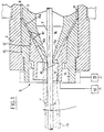
- Fig. 1 is a diametrical sectional view of an extruder head in accordance with a preferred embodiment of the present invention under centering conditions of the female mould;
- Fig. 2 is a diametrical sectional view of the extruder head of Fig. 1 under a maximum eccentricity situation of the female mould;
- Fig. 3 is a diagrammatic top view of the extruder head shown in Fig. 1 associated with an extruder and acting operatively on a semifinished product;
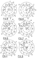
- Figs. 4 to 9 are schematic diagrams showing different work conditions taken by the female mould and reproducing reading scales for identifying the amount and orientation of the eccentricity of said female mould.
- Referring to the drawings, an extruder head for applying coating mixtures to semifinished products of elongated cylindrical configuration in accordance with the present invention has been generally identified by
reference numeral 1. - The extruder head conventionally comprises a supporting
body 2 of substantially cylindrical configuration, fastened to an extruder 3 (Fig. 3) which in known manner is designed to work one or more components previously introduced into acharging hopper 4, so as to obtain a mixture of polymeric material in the plastic state which is injected into theextruder head 1. - Coaxially fastened to the supporting
body 2 of theextruder head 1 is amale mould 5 longitudinally passed through by acentral duct 6 along which asemifinished product 7 is worked. - In greater detail, the
semifinished product 7 consisting for example of an electric conductor, a wire, a cord, a cable or another article of substantially cylindrical configuration, is continuously infed by means not shown as known per se and not of importance to the ends of the invention, so that it emerges from thecentral duct 6 at anoutlet end 5a of themale mould 5 substantially of truncated conical form. - Formed between the
male mould 5 and the supportingbody 2 is a hollow feed gap into which the above mixture in a plastic state is introduced through means not shown as known per se and conventional connecting the gap to the extruder 3. The mixture being constantly pushed since it is acted upon by the extruder 3, continuously flows towards theoutlet end 5a of themale mould 5. - Also housed in the supporting
body 2 is at least afemale mould 9 conformed such as to form ashaped housing 10 disposed about theoutlet end 5a of themale mould 5 in order to define, together with the outlet end itself, anoutflow port 11 for the mixture. Thisoutflow port 11 therefore communicates with thehollow feed gap 8 and surrounds thesemifinished product 7 emerging from themale mould 5. - The mixture coming from the
feed gap 8 will be therefore applied in the form of acontinuous layer 7a to thesemifinished product 7 emerging from themale mould 5. - In accordance with the invention the
female mould 9 comprises at least acentering element 12 provided with a first hole of truncatedconical form 12a defining theoutflow port 11 and at least part of theshaped housing 10. Thecentering element 12 can rotate according to an oblique and incident axis "y" through an angle "α" of predetermined amplitude, relative to the axis of the firstfrustoconical hole 12a and to the axis "x" of thecentral duct 6, and therefore of thesemifinished product 7. - The first
frustoconical hole 12a is made so as to be coaxial with thecentral duct 6 at a predetermined rotational position of the centeringelement 12. - In greater detail, the geometric shape of the first
frustoconical hole 12a is substantially defined by a frustum of cone of oblique axis relative to the rotational axis "y" of thecentering element 12 and coincident with axis "x" in said predetermined position. - By virtue of the misalignment between the above axes, as a result of an angular rotation of the
centering element 12 about its own rotational axis "y", a displacement of theoutflow port 11 relative to theoutlet end 5a of themale mould 5 is achieved. - In particular by the angular rotation of the
centering element 12 the shape of theoutflow port 11 is modified from a centered configuration relative to thecentral duct 6, as shown in Fig. 1, to a configuration in which theduct 6 is eccentric, as shown in Fig. 2. - The angular rotation performed by the
centering element 12 in order to modify the configuration of theoutflow port 11 between the above mentioned two end positions conveniently equals 180°. - For rotational angles of the centering elements ranging between 0° and 180°, the
outflow port 11 will take different eccentricity values included between a zero value and a maximum value, to be selectively used depending upon requirements. - The centering
element 12 is mounted with no possibility of axial movement within anintermediate collar 13 in turn axially locked in the supportingbody 2 and rotating in coaxial relation with thecentral duct 6. - The
intermediate collar 13 exhibits asecond hole 13a of truncated conical form, coaxial with thecentral duct 6 and defining part of said shapedhousing 10. - The second
frustoconical hole 13a substantially extends in a continuity relationship between thehollow feed gap 8 and thefrustoconical hole 12a formed in the centeringelement 12. - This continuity relationship is substantially maintained irrespective of the positioning taken by the first
frustoconical hole 12a, during the displacement of theoutflow port 11 from the centered position to the maximum-eccentricity position, as clearly viewed from comparing Figs. 1 and 2. - The above ensures that under any operating condition of the
extruder head 1 the mixture will not be subjected to encountering discontinuities in its flow travel, in particular in the passage area between thecollar 13 andelement 12, that could give rise to localized stagnations of the mixture. - When the
intermediate collar 13 is rotated within the supportingbody 2, carrying along the centeringelement 12 therewith, the spatial orientation of the common lying plane of axes "y", "x" of the centering element andcentral duct 6 is modified, as well as at the same time, the orientation of the eccentricity plane containing the axes of theoutflow port 11 andcentral duct 6. - Therefore, should for any reason an undesired unevenness in the thickness of the
mixture layer 7a applied to thesemifinished product 7 occur, as shown in Fig. 1, this anomaly could be corrected by imparting appropriate angular rotations to the centeringelement 12 andintermediate collar 13. - In particular, the centering
element 12 is provided to be rotated about its axis "y" so as to give theoutflow port 11 an eccentricity of predetermined value, in correlation with the eccentricity that can be undesirably exhibited by themixture layer 7a relative to thesemifinished product 7 so as to carry out the compensation thereof. Therefore, by acting on theintermediate collar 13 it is possible to bring the plane in which the desired eccentricity of theoutflow port 11 has been achieved to the appropriate angular position, for example a position having opposite way with respect to the eccentricity of themixture layer 7a, so that the last mentioned eccentricity will be neutralised on the product coming out of theextruder head 1, as shown in Fig. 2. - The rotations of the centering
element 12 andintermediate collar 13 can be controlled by hand or with the aid of driving members 9a, 12b, consisting for example of lever tools diagrammatically shown in Fig. 2, adapted to be engaged with the centeringelement 12 andcollar 13. - The manual control can be achieved with the aid of mechanical driving members engaged to the supporting
body 2 andintermediate collar 13 respectively and in engagement with corresponding paired driving members carried by the intermediate collar itself and centeringmember 12 respectively. - These mechanical driving members for example can consist of gearing, worm screws or the like and are therefore adapted to enable the remote eccentricity adjustment.
- Therefore the eccentricity adjustment can be executed manually, by identifying the occurrence of a defect in the extruded coating and, based on the manually detected data, piloting the appropriate rotations of tools 9a, 12b or the mechanical driving members adapted for the purpose.
- Referring particularly to fig. 3, it is also provided that the rotation of the centering
element 12 andintermediate collar 13 should be governed by first and second actuator means 14, 15 consisting for example of servomotors adapted to move said mechanical driving members, causing the desired rotations. - Said actuator means 14, 15 can be driven either directly or automatically through control means 17 acting on the product being worked downstream of the
extruder head 1, with reference to the advancing direction of thesemifinished product 7. - More particularly the control means 17, through respective sensing members not described or shown as known and conventional, continuously detects the thickness of the
coating mixture 7a applied to thesemifinished product 7. - An
electronic control box 18 receives the signals coming from the control means 17 and causes the operation of the actuator means 14, 15 so as to modify the eccentricity of theoutflow port 11 by the angular rotation consequently imparted to the centeringelement 12 and/or theintermediate collar 13, in order to correct the anomaly found in the product being worked. - As shown by way of example in Figs. 4 to 9, in order to facilitate the manual adjustment or enable the automatic adjustment to be duly checked, provision may be also made for reading means 19 to be disposed between the centering
element 12 and theintermediate collar 13, which will enable the immediate identification of the eccentricity of theoutflow port 11 relative to the axis "x" of thecentral duct 6, as well as the orientation of the eccentricity plane containing the axes "z" "x" of the outflow port and central duct. - This reading means 19 comprises one series of indices 19a, denoted by O, A, B, C, D, reproduced on the centering
element 12, and a second series of indices 19b denoted by O', A', B', C', D', formed on theintermediate collar 13. A given eccentricity value of theoutflow port 11 corresponds to each of the indices of the first series O, A, B, C, D, and second series O', A', B', C', D', individually correlated with each other. - In this connection it is to be noted that letters A, B, C, D, A', B', C', D' can be replaced with the real eccentricity values corresponding to them, expressed under metric or percent form.
- Indices of the first series O, A, B, C, D and second series O', A', B', C', D' are shown in an increasing order in respectively opposite directions and according to respective arcs of circumferences spaced apart by the same distance on an angular amplitude equal to half the angular travel carried out by the centering
element 12 for bringing theoutflow port 11 from the centered position to the maximum-eccentricity position. - In this way a rotation according to which the last symbol of the first series is disposed in front of the last symbol of the second series corresponds to a complete angular travel of
element 12. - Should different angular travels be desired due to different requirements, it will be possible to correspondingly make the respective indication scales. When one of the indices of the first series, for example index B, is brought into coincidence with the corresponding index B' (Fig. 6) being part of the second series, a given eccentricity value of the
outflow port 11 is created which can be numerically reproduced on said coincident indices. - In addition, with this geometry the plane in which indices B, B' belonging to the first and second series respectively, in coincidence with each other, have been disposed is advantageously also coincident with the plane in which the eccentricity containing axis "z" of the
outflow port 11 and axis "x" of thecentral duct 6 has been determined. - Therefore the mutually coincident indices also show the orientation of this eccentricity plane, according to the representation given in Figs. 4 to 9 (dotted lines "k").
- The presence of auxiliary reading means 20 can also be provided. Said means is formed between the supporting
body 2 and theintermediate collar 13 and is designed to point out the angular orientation of the collar relative to said supporting body constituting a fixed reference. - This auxiliary reading means 20 comprises a
goniometric scale 20a circumferentially reproduced on the supportingbody 2 and one ormore read indices 20b reproduced on theintermediate collar 13. - It is to be noted that for the sake of clarity in the graphic representation, angle "α" in Figs. 1 and 2 and the consequent maximum eccentricity value of the
outflow port 11 have been deliberately raised. - In a practical preferred embodiment given by way of example, for coating an electric cable of a 10 mm diameter with a 2.5 mm thick layer of mixture, the rotational axis "y" of the centering element has been provided to be incident on axis "x" of the
central duct 6 in the transition plane between the first and secondfrustoconical holes - At all events, the maximum eccentricity to be given to the
outflow port 11 is preferably provided to be at least equal to 20% of the thickness of themixture layer 7a to be applied to the semifinished product, and angle "α" is provided to have a value included between 1° and 5°. - Values of angle "α" lower than the stated range could require too great a length value of the
female mould 9. On the other hand, values of angle "α" higher than stated could involve, under some angular positions, important deflections to the mixture flow between the surfaces ofhole 13a andhole 12a. - Within the scope of the present invention in case of extruders providing for the covering of the semifinished product with several mixture layers, it is also possible to adopt one or more additional female moulds adapted for separately forming said layers.
- Each of said additional moulds is comprised of a centering element and an intermediate collar in the same manner as above described so that the eccentricity of all mixture layers applied to the semifinished product can be corrected.
- The extruder head in question enables the geometrical conformation of the mixture layer or layers to be adjusted in a practical and precise manner, while keeping a particularly simple mechanical structure.
- Advantageously, unlike the case of known devices having a female mould movable in a plane perpendicular to the axis of the central duct, the present invention enables the conformation of the female mould to be suitably modified without involving the formation of sharp localized deflections in the path travelled by the mixture, which would bring about, as a result, undesired stagnation or slowing-down areas in the material flow.
- These slowing-down or stagnation areas must be avoided as much as possible, since they could give rise to the formation of small clots above all when materials that can be cross-linked or at all events materials susceptible of alteration under the effect of a prolonged heating are used. Said clots, when subsequently conveyed into the mixture flow, would give origin to unacceptable irregularities in the coating applied to the semifinished product that, in particular in the case of insulating coatings for electrical cables, could result in an undesired decay of the dielectric characteristics of the material.
- The rotation of
element 12 withincollar 13, on the contrary, only causes a slight variation of the surface inclination in the transition area betweensurface 13a andsurface 12a to occur on varying the eccentricity, which variation does not affect the behaviour of the material flow. - It is also to be pointed out that, unlike the known art and in particular unlike the solutions in which the female mould is designed to swing about a ball joint, the extruder head in question keeps a very simple structure, adapted to be easily dismantled for servicing purposes and for carrying out the control and/or replacement of the components thereof and that it lends itself both to a remote control and to an automatic control of the eccentricity, during the production.
- Obviously modifications and variations can be made to the invention as conceived, all of them falling within the scope of the dependent claims.
Claims (15)
- An extruder head for applying a coating of polymeric material to semifinished products of elongated cylindrical conformation comprising:- a fixed supporting body (2);- a male mould (5) fastened to the inside of the supporting body (2), having a tapered end portion (5a) substantially of truncated conical form and a central duct (6) susceptible of being longitudinally passed through by a continuously-infed cylindrical semifinished product (7) emerging from the end of said end portion (5a) of the male mould (5);- connecting means for connection to an extruder (3), designed to feed at least a polymeric material in the plastic state into a hollow feed gap (8) formed between the supporting body (2) and the male mould (5);- at least a female mould (9) provided with a shaped housing (10) disposed around the end portion (5a) of the male mould (5), defining, in cooperation therewith, a passage channel for said material, said channel communicating with the feed gap (8) and forming an annular outflow port (11) at the opposite end thereof, through which a layer of material (7a) is applied to the semifinished product (7),
said female mould (9) comprising at least a centering element (12) exhibiting one hole (12a) of truncated conical form at least partly defining said shaped housing (10), and defining said outflow port (11) at the end thereof,
characterized in that said centering element (12) is rotatable around an axis (y) which is oblique and is incident to the axis (x) of said central duct (6) so as to bring the outflow port (11) to a position to be selected, between a centered position and a maximum-eccentricity position relative to said central duct (6). - An extruder head according to claim 1, characterized in that said female mould (9) in addition comprises an intermediate collar (13) rotatably carrying said centering element (12), said intermediate collar (13) being in turn engaged to the supporting body (2) in a rotating manner in coaxial relation with the central duct (6) for arranging an eccentricity plane containing the axes of the central duct (6) and the outflow port (11) in the desired orientation.
- An extruder head according to claim 1, characterized in that the displacement of the outflow port (11) from the centering position to the maximum-eccentricity position corresponds to an angular rotation through 180° of the centering element (12) about its own axis of rotation (y).
- An extruder head according to claim 1, characterized in that the maximum eccentricity of the outflow port (11) relative to the axis (y) of the central duct (6) is at least equal to 20% of the thickness of said layer of material (7a) applied to the semifinished product (7).
- An extruder head according to claim 1, characterized in that the angle of incidence of the rotational axis of the centering element (12) to the axis of the central duct (6) is in the range of 1° to 5°.
- An extruder head according to claim 1, characterized in that the first hole (12a) of truncated conical form exhibited by the centering element (12) has an oblique axis relative to the rotational axis of the centering element itself forming an angle equal to the angle of incidence of the centering element (12) axis on the central duct (6) axis.
- An extruder head according to claim 2, characterized in that said intermediate collar (13) exhibits a second hole (13a) of truncated conical form, coaxial with the central duct (6), partly defining said shaped housing (10) and extending in a continuity relationship between the hollow feed gap (8) and the first hole (12a) of truncated conical form formed in the centering element (12).
- An extruder head according to claim 2, characterized in that reading means (19) is provided between the centering element (12) and the intermediate collar (13) for identifying the rotational axis of the centering element (12) relative to the intermediate collar (13) and, in connection therewith, the eccentricity value of the outflow port (11) relative to the axis of the central duct (6) and the orientation of the eccentricity plane containing the axes of the outflow port (11) and the central duct (6), with respect to the body (2).
- An extruder head according to claim 8, characterized in that said reading means (19) comprises one series of indices (O, A, B, C, D) and a second series of indices (O', A', B', C', D') reproduced on the centering element (12) and the intermediate collar (13) respectively and circumferentially distributed following an increasing order in respectively opposite directions, according to respective arcs of circumferences of angular amplitude equal to half the angular travel of the centering element (12) corresponding to the displacement of the outflow port (11) from the centered position to the maximum-eccentricity position, each index of the first series being arranged to be selectively brought into register with a corresponding index belonging to the second series in order to indicate the value of said eccentricity.
- An extruder head according to claim 9, characterized in that the alignment position of the corresponding indices of the first and second series identifies the orientation of said plane of eccentricity.
- An extruder head according to claim 2, characterized in that formed between the intermediate (13) collar and the supporting body (2) is auxiliary reading means (20) adapted to indicate the angular orientation of the collar itself relative to said supporting body (2).
- An extruder head according to claim 11, characterized in that said auxiliary reading means (20) comprises at least a goniometric scale (20a) reproduced on the supporting body (2), and at least a reference index (20b) reproduced on the intermediate collar (13).
- An extruder head according to claim 1, characterized in that it comprises remote control actuator means (14), operatively connected to said centering element (12) through respective driving means (12b) designed to cause an angular rotation of the latter, of amplitude to be established in advance, about its own axis (y).
- An extruder head according to claim 2, characterized in that it comprises remote control actuator means (15) operatively connected to said intermediate collar (13) through respective driving means (9a) adapted to cause an angular rotation of the latter of amplitude to be established in advance.
- An extruder head according to claim 2, characterized in that it comprises first and second actuator means (14, 15) acting on the entering element (12) and intermediate collar (13) respectively, through respective driving means (9a, 12b) operatively connected to detection and control means (17, 18) for establishing the thickness of the mixture layer (7a) applied to the semifinished product (7), located downstream of the outflow port (11) and adapted to operate said first and second actuator means (14, 15) in order to cause respective angular rotations of the centering element (12) and intermediate collar (13) about their respective axes of rotation, correspondingly to the thickness eccentricity values of the mixture layer (7a) and to the lying of said eccentricity detected by the control means itself (17).
Applications Claiming Priority (2)
| Application Number | Priority Date | Filing Date | Title |
|---|---|---|---|
| ITMI911296A IT1247920B (en) | 1991-05-13 | 1991-05-13 | EXTRUSION HEAD TO APPLY POLYMERIC MATERIAL COATINGS ON SEMI-FINISHED CYLINDRICAL CONFORMATION WORKS |
| ITMI911296 | 1991-05-13 |
Publications (2)
| Publication Number | Publication Date |
|---|---|
| EP0513616A1 EP0513616A1 (en) | 1992-11-19 |
| EP0513616B1 true EP0513616B1 (en) | 1996-06-26 |
Family
ID=11359883
Family Applications (1)
| Application Number | Title | Priority Date | Filing Date |
|---|---|---|---|
| EP92107518A Expired - Lifetime EP0513616B1 (en) | 1991-05-13 | 1992-05-04 | Extruder head for applying coatings of polymeric material to semifinished products of elongated cylindrical conformation |
Country Status (6)
| Country | Link |
|---|---|
| US (1) | US5286183A (en) |
| EP (1) | EP0513616B1 (en) |
| AT (1) | ATE139732T1 (en) |
| DE (1) | DE69211772T2 (en) |
| FI (1) | FI98715C (en) |
| IT (1) | IT1247920B (en) |
Cited By (1)
| Publication number | Priority date | Publication date | Assignee | Title |
|---|---|---|---|---|
| EP4491367A1 (en) | 2016-12-08 | 2025-01-15 | BizLink Industry Germany GmbH | Extrusion device, extruder and method for sheathing wires, cable fabricated materials or strands |
Families Citing this family (22)
| Publication number | Priority date | Publication date | Assignee | Title |
|---|---|---|---|---|
| JP2620194B2 (en) * | 1993-07-21 | 1997-06-11 | アルファー技研工業株式会社 | Outer diameter control start-up method and outer diameter start-up control device for wire coating line |
| NL9400602A (en) * | 1994-04-15 | 1995-11-01 | Townsend Engineering Co | A method of manufacturing food strands with a protein molded sleeve and apparatus for carrying out the method. |
| US5643618A (en) * | 1994-05-11 | 1997-07-01 | General Mills, Inc. | Apparatus for making multiple, complexly patterned extrudates |
| FI98284C (en) * | 1995-09-12 | 1997-05-26 | Uponor Bv | Apparatus and method for making a plastic pipe |
| US5630982A (en) * | 1995-12-12 | 1997-05-20 | Sonoco Products Company | Method and apparatus for extruding plastic tubing |
| US5843503A (en) * | 1997-02-24 | 1998-12-01 | General Mills, Inc. | Apparatus and method for making multiple patterned extrudates |
| US6382944B1 (en) * | 1998-11-10 | 2002-05-07 | Guill Tool & Engineering Co., Inc. | Universally mounted adjustable die |
| US6902388B2 (en) * | 1998-11-10 | 2005-06-07 | Guill Tool And Engineering Co., Inc. | Pivotally adjustable die |
| US6251452B1 (en) | 1999-04-23 | 2001-06-26 | General Mills, Inc. | Apparatus and methods for making multiple, complexly patterned extrudates |
| DE19936823C2 (en) * | 1999-08-05 | 2003-06-26 | Hosokawa Bepex Gmbh | Nozzle carrier and device for extruding doughy masses |
| JP4089113B2 (en) * | 1999-12-28 | 2008-05-28 | 株式会社Ihi | Thin film production equipment |
| FI108412B (en) | 2000-03-28 | 2002-01-31 | Nextrom Holding Sa | Arrangements in connection with press tools |
| DE10027564A1 (en) * | 2000-06-02 | 2001-12-06 | Alcatel Sa | Process for the production of twisted pairs |
| US6915647B2 (en) * | 2003-05-21 | 2005-07-12 | Hoshizaki Denki Kabushiki Kaisha | Abnormality detecting device of auger-type ice making machine and abnormality detecting method thereof |
| JP5347907B2 (en) * | 2009-10-29 | 2013-11-20 | 豊田合成株式会社 | Method for extruding tube body and apparatus for extruding tube body |
| DE102011118719A1 (en) * | 2011-11-16 | 2013-05-16 | Brabender Gmbh & Co.Kg | Apparatus for extruding a medical instrument insertable into a human or animal body |
| JP2015033767A (en) * | 2013-08-07 | 2015-02-19 | 住友ゴム工業株式会社 | Manufacturing method of conductive foam rubber roller, conductive foam rubber roller, and image forming apparatus |
| DE102013109495B3 (en) * | 2013-08-30 | 2014-08-14 | Harald Feuerherm | Extrusion tool for the production of tubular preforms |
| US9808991B2 (en) * | 2014-07-29 | 2017-11-07 | Cc3D Llc. | Method and apparatus for additive mechanical growth of tubular structures |
| US10105910B2 (en) * | 2016-04-15 | 2018-10-23 | Cc3D Llc | Method for continuously manufacturing composite hollow structure |
| CN106373668B (en) * | 2016-09-16 | 2017-06-13 | 芜湖市旭辉电工新材料有限责任公司 | A kind of cable insulation extrusion equipment of automatic concentricity adjusting |
| US11312055B2 (en) * | 2018-10-01 | 2022-04-26 | Homar Cisneros | Method of adjusting a crosshead extruder die retaining assembly |
Family Cites Families (15)
| Publication number | Priority date | Publication date | Assignee | Title |
|---|---|---|---|---|
| DE948625C (en) * | 1941-06-21 | 1956-09-06 | Siemens Ag | Pipe extrusion press |
| GB808283A (en) * | 1954-10-25 | 1959-02-04 | Buzuluk Komarov | An axial extruding machine |
| DE1107926B (en) * | 1956-08-01 | 1961-05-31 | Reifenhaeuser Kg | Injection head on extrusion presses for the production of curved tubes or rods from organic thermoplastic or other thermoplastic compounds |
| BE557897A (en) * | 1957-06-03 | 1957-06-15 | ||
| US3382539A (en) * | 1966-08-04 | 1968-05-14 | Continental Can Co | Extrusion die shell adjustment |
| DE1948580A1 (en) * | 1968-09-30 | 1970-04-09 | Unilever Nv | Appts for radial and axial adjustment of an extrusion - nozzle core and sleeve |
| DE1908933B2 (en) * | 1969-02-22 | 1971-04-29 | EXTRUSION HEAD FOR EXTRUSION OF A HOSE | |
| US3923439A (en) * | 1972-10-10 | 1975-12-02 | Western Electric Co | System for controlling the eccentricity of an extruded article |
| US4137745A (en) * | 1976-03-05 | 1979-02-06 | Muratov Rustem I | Device for extruding hollow articles |
| JPS5315547A (en) * | 1976-07-28 | 1978-02-13 | Tokyo Electric Power Co Inc:The | Inspection method for digital protective relays |
| DE3216377A1 (en) * | 1981-09-26 | 1983-06-16 | Detlef Dipl.-Ing. 4970 Bad Oeynhausen Gneuss | DEVICE FOR PRODUCING TUBES FROM PLASTIC MEASURES |
| US4525131A (en) * | 1983-08-29 | 1985-06-25 | Alcan Aluminum Corporation | Cable-coating extruder head system with changeable die and guider elements |
| CH667327A5 (en) * | 1984-06-18 | 1988-09-30 | Zumbach Electronic Ag | METHOD AND DEVICE FOR TESTING THE WALL THICKNESS OF AN INSULATING LAYER. |
| CA1222363A (en) * | 1986-04-16 | 1987-06-02 | Northern Telecom Limited | Apparatus for insulating electrical conductor |
| DE3619005A1 (en) * | 1986-06-05 | 1987-12-10 | Kabelmetal Electro Gmbh | Apparatus for forming extrudable metallic or nonmetallic materials |
-
1991
- 1991-05-13 IT ITMI911296A patent/IT1247920B/en active IP Right Grant
-
1992
- 1992-05-04 DE DE69211772T patent/DE69211772T2/en not_active Expired - Lifetime
- 1992-05-04 AT AT92107518T patent/ATE139732T1/en not_active IP Right Cessation
- 1992-05-04 EP EP92107518A patent/EP0513616B1/en not_active Expired - Lifetime
- 1992-05-08 US US07/880,742 patent/US5286183A/en not_active Expired - Lifetime
- 1992-05-12 FI FI922150A patent/FI98715C/en not_active IP Right Cessation
Cited By (1)
| Publication number | Priority date | Publication date | Assignee | Title |
|---|---|---|---|---|
| EP4491367A1 (en) | 2016-12-08 | 2025-01-15 | BizLink Industry Germany GmbH | Extrusion device, extruder and method for sheathing wires, cable fabricated materials or strands |
Also Published As
| Publication number | Publication date |
|---|---|
| DE69211772T2 (en) | 1997-02-06 |
| ITMI911296A0 (en) | 1991-05-13 |
| ATE139732T1 (en) | 1996-07-15 |
| FI98715C (en) | 1997-08-11 |
| ITMI911296A1 (en) | 1992-11-13 |
| FI98715B (en) | 1997-04-30 |
| FI922150A7 (en) | 1992-11-14 |
| DE69211772D1 (en) | 1996-08-01 |
| EP0513616A1 (en) | 1992-11-19 |
| FI922150A0 (en) | 1992-05-12 |
| IT1247920B (en) | 1995-01-05 |
| US5286183A (en) | 1994-02-15 |
Similar Documents
| Publication | Publication Date | Title |
|---|---|---|
| US5286183A (en) | Extruder head for applying coatings of polymeric material to semifinished products of elongated cylindrical conformation | |
| US4240863A (en) | Control system for an elastomer extrusion and applicator apparatus | |
| US5711349A (en) | Flow divider with diverter valve | |
| US3940221A (en) | Thickness control system for an extrusion die | |
| EP0457991B1 (en) | Multiple layer die head with adjustable gaps | |
| US3502752A (en) | Control of the dimensions of multiple layers of extruded insulation | |
| US3752614A (en) | Adjustable extrusion head | |
| CN112908562B (en) | System for automatically adjusting core deviation degree of cable | |
| US2977632A (en) | Centripetal extruder | |
| EP0180571A3 (en) | Extrusion die arrangement and automatic centering extrusion method | |
| US4605525A (en) | Method for forming insulating electrical conductor | |
| JP2005531429A (en) | Apparatus and method for continuously producing reinforcement-reinforced hose-like structures | |
| US20190291325A1 (en) | Extrusion system, extruder and method for coating wires, cable pre-products or stranded conductors | |
| US4548570A (en) | Extrusion apparatus for producing thermoplastic pipe | |
| CA1222363A (en) | Apparatus for insulating electrical conductor | |
| EP0834386B1 (en) | Apparatus for producing double walled plastic pipes | |
| US5836680A (en) | Extruder with feedback loop control | |
| WO1985000138A1 (en) | Apparatus and method for controlling internal size of an extruded hose | |
| JP7464624B2 (en) | Casting thin film manufacturing equipment and thin film stretching equipment equipped with casting thin film manufacturing equipment | |
| US3914147A (en) | Apparatus and method for the continuous production of wound pipes | |
| US4512943A (en) | Extrusion process for producing thermoplastic pipe | |
| US3820927A (en) | Dual layer crosshead system | |
| EP4159405B1 (en) | A polymeric tube forming apparatus with a multi-dimensional control system | |
| US4174935A (en) | Extrusion apparatus for producing elongated core members covered with concentric coatings | |
| EP0887172A1 (en) | Plastics extrusion |
Legal Events
| Date | Code | Title | Description |
|---|---|---|---|
| PUAI | Public reference made under article 153(3) epc to a published international application that has entered the european phase |
Free format text: ORIGINAL CODE: 0009012 |
|
| AK | Designated contracting states |
Kind code of ref document: A1 Designated state(s): AT CH DE FR LI |
|
| 17P | Request for examination filed |
Effective date: 19930507 |
|
| RAP1 | Party data changed (applicant data changed or rights of an application transferred) |
Owner name: PIRELLI CAVI S.P.A. |
|
| 17Q | First examination report despatched |
Effective date: 19940926 |
|
| GRAH | Despatch of communication of intention to grant a patent |
Free format text: ORIGINAL CODE: EPIDOS IGRA |
|
| GRAH | Despatch of communication of intention to grant a patent |
Free format text: ORIGINAL CODE: EPIDOS IGRA |
|
| GRAA | (expected) grant |
Free format text: ORIGINAL CODE: 0009210 |
|
| AK | Designated contracting states |
Kind code of ref document: B1 Designated state(s): AT CH DE FR LI |
|
| REF | Corresponds to: |
Ref document number: 139732 Country of ref document: AT Date of ref document: 19960715 Kind code of ref document: T |
|
| REF | Corresponds to: |
Ref document number: 69211772 Country of ref document: DE Date of ref document: 19960801 |
|
| REG | Reference to a national code |
Ref country code: CH Ref legal event code: NV Representative=s name: FIAMMENGHI-FIAMMENGHI |
|
| ET | Fr: translation filed |
Free format text: CORRECTIONS |
|
| PLBE | No opposition filed within time limit |
Free format text: ORIGINAL CODE: 0009261 |
|
| STAA | Information on the status of an ep patent application or granted ep patent |
Free format text: STATUS: NO OPPOSITION FILED WITHIN TIME LIMIT |
|
| 26N | No opposition filed | ||
| REG | Reference to a national code |
Ref country code: FR Ref legal event code: TP Ref country code: FR Ref legal event code: CD |
|
| REG | Reference to a national code |
Ref country code: CH Ref legal event code: PUE Owner name: PRYSMIAN CAVI E SISTEMI ENERGIA S.R.L. Free format text: PIRELLI CAVI S.P.A.#VIALE SARCA, 222#I-20126 MILANO (IT) -TRANSFER TO- PRYSMIAN CAVI E SISTEMI ENERGIA S.R.L.#VIALE SARCA 222#20126 MILANO (IT) |
|
| PGFP | Annual fee paid to national office [announced via postgrant information from national office to epo] |
Ref country code: FR Payment date: 20100601 Year of fee payment: 19 |
|
| PGFP | Annual fee paid to national office [announced via postgrant information from national office to epo] |
Ref country code: AT Payment date: 20100421 Year of fee payment: 19 Ref country code: DE Payment date: 20100527 Year of fee payment: 19 |
|
| PGFP | Annual fee paid to national office [announced via postgrant information from national office to epo] |
Ref country code: CH Payment date: 20100525 Year of fee payment: 19 |
|
| REG | Reference to a national code |
Ref country code: CH Ref legal event code: PL |
|
| PG25 | Lapsed in a contracting state [announced via postgrant information from national office to epo] |
Ref country code: LI Free format text: LAPSE BECAUSE OF NON-PAYMENT OF DUE FEES Effective date: 20110531 Ref country code: CH Free format text: LAPSE BECAUSE OF NON-PAYMENT OF DUE FEES Effective date: 20110531 |
|
| REG | Reference to a national code |
Ref country code: AT Ref legal event code: MM01 Ref document number: 139732 Country of ref document: AT Kind code of ref document: T Effective date: 20110504 |
|
| REG | Reference to a national code |
Ref country code: FR Ref legal event code: ST Effective date: 20120131 |
|
| PG25 | Lapsed in a contracting state [announced via postgrant information from national office to epo] |
Ref country code: AT Free format text: LAPSE BECAUSE OF NON-PAYMENT OF DUE FEES Effective date: 20110504 |
|
| REG | Reference to a national code |
Ref country code: DE Ref legal event code: R119 Ref document number: 69211772 Country of ref document: DE Effective date: 20111201 |
|
| PG25 | Lapsed in a contracting state [announced via postgrant information from national office to epo] |
Ref country code: FR Free format text: LAPSE BECAUSE OF NON-PAYMENT OF DUE FEES Effective date: 20110531 |
|
| PG25 | Lapsed in a contracting state [announced via postgrant information from national office to epo] |
Ref country code: DE Free format text: LAPSE BECAUSE OF NON-PAYMENT OF DUE FEES Effective date: 20111201 |