EP0511251B1 - Apparatus for displaying material under refrigerated conditions - Google Patents
Apparatus for displaying material under refrigerated conditions Download PDFInfo
- Publication number
- EP0511251B1 EP0511251B1 EP91902133A EP91902133A EP0511251B1 EP 0511251 B1 EP0511251 B1 EP 0511251B1 EP 91902133 A EP91902133 A EP 91902133A EP 91902133 A EP91902133 A EP 91902133A EP 0511251 B1 EP0511251 B1 EP 0511251B1
- Authority
- EP
- European Patent Office
- Prior art keywords
- air
- evaporator
- display compartment
- temperature
- display
- Prior art date
- Legal status (The legal status is an assumption and is not a legal conclusion. Google has not performed a legal analysis and makes no representation as to the accuracy of the status listed.)
- Expired - Lifetime
Links
Images


Classifications
-
- A—HUMAN NECESSITIES
- A47—FURNITURE; DOMESTIC ARTICLES OR APPLIANCES; COFFEE MILLS; SPICE MILLS; SUCTION CLEANERS IN GENERAL
- A47F—SPECIAL FURNITURE, FITTINGS, OR ACCESSORIES FOR SHOPS, STOREHOUSES, BARS, RESTAURANTS OR THE LIKE; PAYING COUNTERS
- A47F3/00—Show cases or show cabinets
- A47F3/04—Show cases or show cabinets air-conditioned, refrigerated
- A47F3/0478—Control or safety arrangements
-
- A—HUMAN NECESSITIES
- A47—FURNITURE; DOMESTIC ARTICLES OR APPLIANCES; COFFEE MILLS; SPICE MILLS; SUCTION CLEANERS IN GENERAL
- A47F—SPECIAL FURNITURE, FITTINGS, OR ACCESSORIES FOR SHOPS, STOREHOUSES, BARS, RESTAURANTS OR THE LIKE; PAYING COUNTERS
- A47F10/00—Furniture or installations specially adapted to particular types of service systems, not otherwise provided for
- A47F10/06—Furniture or installations specially adapted to particular types of service systems, not otherwise provided for for restaurant service systems
-
- A—HUMAN NECESSITIES
- A47—FURNITURE; DOMESTIC ARTICLES OR APPLIANCES; COFFEE MILLS; SPICE MILLS; SUCTION CLEANERS IN GENERAL
- A47F—SPECIAL FURNITURE, FITTINGS, OR ACCESSORIES FOR SHOPS, STOREHOUSES, BARS, RESTAURANTS OR THE LIKE; PAYING COUNTERS
- A47F3/00—Show cases or show cabinets
- A47F3/04—Show cases or show cabinets air-conditioned, refrigerated
- A47F3/0439—Cases or cabinets of the open type
- A47F3/0443—Cases or cabinets of the open type with forced air circulation
Definitions
- This invention relates to apparatus for displaying food or other material under refrigerated conditions.
- DK-B-159 004 discloses a refrigerated display cabinet having a display compartment and an air circulation fan controlled in such a way that, when the cabinet is covered while a store is not open for business, the fan is started and stopped periodically in accordance with a predetermined and variable schedule.
- the temperature of the air is controlled by a thermostat which controls an evaporator and a compressor, and is responsive to a first sensor located at the outlet of the air from the display compartment.
- the temperature in the display compartment is further separately controlled by the continuous or intermittent operation of a fan located downstream of the evaporator, depending upon whether the cover to the display compartment is open or closed.
- a first switch When the fan is being operated continuously, as during store hours, a first switch is open and a second switch is closed. During off hours, the fan is operated intermittently by a timer when the first switch is closed and the second switch is open.
- the timer may be set manually or may be controlled automatically by a second sensor at the air inlet to the display case.
- the compressor/evaporator and the fan of the refrigeration means are independently controlled by respective sensors.
- US-A-4 117 698 discloses multi-curtain, open-front refrigerated display apparatus having a reverse air flow defrost system controlled by a demand defrost controller, responsive to a predetermined difference in temperature as detected by an inlet sensor located at the inlet side of a refrigerating coil and an outlet sensor located at the outlet side of the coil.
- the installations currently used for the refrigerated display of food tend to suffer from uneven temperature distribution in the display compartment, leading to food in some areas of the display compartment being at undesirably high temperatures and food in other areas being at undesirably low temperatures.
- An aim of the present invention is to minimise this drawback.
- apparatus for displaying material under refrigerated conditions comprising a display compartment, refrigeration means for generating a stream of cooled air which passes through the display compartment, an air inlet sensor for sensing the temperature of the air at the inlet to the display compartment, an air outlet sensor for sensing the temperature of the air at the outlet from the display compartment, and control means for controlling the operation of the refrigeration means, characterised in that the control means is responsive to a signal derived from the output of both the sensors, thereby maintaining the air temperature in the display compartment within a narrow predetermined range.
- control means is responsive to the computed mean of the inlet and outlet temperatures, the computed mean temperature corresponding approximately to the actual temperature approximately at the mid-point between the inlet and outlet.
- the refrigeration means includes a condensor, an evaporator and a fan.
- the fan is a centrifugal fan and is located upstream of the evaporator so that the air stream in the vicinity of the evaporator is slightly pressurised. The fan may then be located near the outlet from the display compartment and in communication with it so that the air follows a closed circuit.
- the fan and the configuration of the display compartment are such that an evenly distributed laminar air flow is achieved.
- a further fan may be located downstream of the evaporator to drive a branch airstream to a refrigerated storage compartment.
- the evaporator has a large surface area, for example at least twice that of a conventional area in the case of a gravity fed unit, allowing it to be operated at a temperature such that moisture is retained in the air stream.
- the humidity of the air stream in the display compartment may thereby be increased by from 10 to 20%, typically about 15%, with respect to ambient relative humidity (RH).
- the evaporator may comprise a conventional coil, in which case the air flow over the evaporator may be so widely distributed that the coil never becomes blocked.
- the higher operating temperature reduces the amount of defrosting necessary.
- the fan speed may be so controlled as to permit automatic air flow defrosting without the need for heaters, thus allowing the temperature of the air flow to be kept at a low level during the de-frosting cycle.
- continuous humidification means for example a humidifier operating by injecting a fine, electronically-created fresh water mist into the air stream.
- a humidifier operating by injecting a fine, electronically-created fresh water mist into the air stream.
- the humidifier allow the relative humidity (RH) in the display compartment to be maintained at a desired level, for example 80% RH, or even 85% RH, within a range of, for example, ⁇ 0.1 - 1.0%, but the visual effect of the misting is attractive to customers.
- the humidifying means includes water softening and cleanse dumping systems.
- Additional preferred features of apparatus include a lift-out tray in the display compartment; pull-out storage drawers located beneath the display compartment; an air intake which is easily removable to allow access to the condenser, the condenser being arranged to be pulled out for service; and access to a condensate drip tray.
- a refrigerated display unit 10 comprises a cabinet 12 mounted on feet 14 and having two refrigerated storage drawers 16,18 and a display compartment comprising a lift-out display tray 20, supporting food 21, and a transparent frame 22. Above the tray 20 there is supported by pillars 23 a canopy 24, and on the front of the cabinet 12 is mounted a tray counter 25.
- the display tray 20 has an air inlet 26 and an air outlet 27, near which is located a baffle plate 28.
- an evaporator 30, of the coil type mounted below the display tray 20 to an evaporator 30, of the coil type, connected to a refrigeration condensing unit 31 which is accessible for cleaning via a drop-down louvred air intake 32, and which can be easily pulled out of the cabinet 12 for service. Access to a condensate drip tray (not shown) is gained through a hinged panel 33.
- Air in a closed circuit passes through a centrifugal fan 36, upstream of the evaporator 30, through the evaporator 30, over the display tray 20 and back to the fan 36, as indicated by arrows 34.
- the baffle plate 28 allows cold air in the display tray to build up to a predetermined height.
- a branch stream is driven downwardly over the drawers 16,18 by a fan 40 downstream of the evaporator 30, as indicated by arrows 38. Above the fan 40 is positioned a guard (not shown) to prevent food being placed immediately thereabove and thus stopping the circulation of air to the drawers 16.
- a humidification unit 42 is arranged to inject a fine mist of softened water into the air leaving the evaporator 30.
- the electronic control system illustrated in Fig. 3 is largely centralised in an electronic control unit 44 (see Fig. 2) and also includes an air inlet temperature sensor 46 and an air outlet temperature sensor 48 for sensing the air temperatures at the inlet 26 and the outlet 27 of the display compartment.
- An associated display 52 displays the mean of the inlet and outlet temperatures as computed by the comparator 49 to give the temperature approximately at the mid-point 50.
- a relative humidity sensor 54 is arranged to give an RH read-out also on the display 52.
- the control system is arranged to control the speed of the fans 36 and 40 and the operation of the refrigeration system via a compressor 59; and also the defrost cycles through sensors 56,58, comparator 60 and defrost selector 62. Additionally, the control system controls the humidifier 42 and its associated water treatment systems, and cabinet lighting.
- the control system By monitoring the computed mid-point temperature to ⁇ 0.1°C the control system enables the temperature range at the rear of the tray 20 to be controlled to ⁇ 1.5°C; at the middle to ⁇ 1°C; and better than ⁇ 2°C at the front. Moreover, the control system allows a choice of mid-point temperatures of + 5 or + 8°C, and a choice of humidity settings up to 85% RH.
- the above-described refrigerated display unit 10 offers a wide variety of improvements over existing units, in particular the capability of maintaining a large open food display at a temperature not exceeding + 5°C over the height of the food.
Abstract
Description
- This invention relates to apparatus for displaying food or other material under refrigerated conditions.
- Such apparatus is widely known. For example, DK-B-159 004 discloses a refrigerated display cabinet having a display compartment and an air circulation fan controlled in such a way that, when the cabinet is covered while a store is not open for business, the fan is started and stopped periodically in accordance with a predetermined and variable schedule. The temperature of the air is controlled by a thermostat which controls an evaporator and a compressor, and is responsive to a first sensor located at the outlet of the air from the display compartment. In addition, the temperature in the display compartment is further separately controlled by the continuous or intermittent operation of a fan located downstream of the evaporator, depending upon whether the cover to the display compartment is open or closed. When the fan is being operated continuously, as during store hours, a first switch is open and a second switch is closed. During off hours, the fan is operated intermittently by a timer when the first switch is closed and the second switch is open. The timer may be set manually or may be controlled automatically by a second sensor at the air inlet to the display case. Thus the compressor/evaporator and the fan of the refrigeration means are independently controlled by respective sensors.
- US-A-4 117 698 discloses multi-curtain, open-front refrigerated display apparatus having a reverse air flow defrost system controlled by a demand defrost controller, responsive to a predetermined difference in temperature as detected by an inlet sensor located at the inlet side of a refrigerating coil and an outlet sensor located at the outlet side of the coil.
- The installations currently used for the refrigerated display of food, for example in a self-service display, tend to suffer from uneven temperature distribution in the display compartment, leading to food in some areas of the display compartment being at undesirably high temperatures and food in other areas being at undesirably low temperatures.
- An aim of the present invention is to minimise this drawback.
- According to the present invention, there is provided apparatus for displaying material under refrigerated conditions, comprising a display compartment, refrigeration means for generating a stream of cooled air which passes through the display compartment, an air inlet sensor for sensing the temperature of the air at the inlet to the display compartment, an air outlet sensor for sensing the temperature of the air at the outlet from the display compartment, and control means for controlling the operation of the refrigeration means, characterised in that the control means is responsive to a signal derived from the output of both the sensors, thereby maintaining the air temperature in the display compartment within a narrow predetermined range.
- Desirably the control means is responsive to the computed mean of the inlet and outlet temperatures, the computed mean temperature corresponding approximately to the actual temperature approximately at the mid-point between the inlet and outlet.
- Preferably the refrigeration means includes a condensor, an evaporator and a fan. In that case preferably the fan is a centrifugal fan and is located upstream of the evaporator so that the air stream in the vicinity of the evaporator is slightly pressurised. The fan may then be located near the outlet from the display compartment and in communication with it so that the air follows a closed circuit. Preferably again the fan and the configuration of the display compartment are such that an evenly distributed laminar air flow is achieved. If desired, a further fan may be located downstream of the evaporator to drive a branch airstream to a refrigerated storage compartment.
- Conventional refrigerated display installations have typically been run with an average temperature in the display compartment of + 10°C. With the current concern over the bacterial contamination of food, such a temperature is not now regarded as sufficiently low, and it is desirable, and may in the future even be necessary, to operate refrigerated display installations at a temperature as low as + 5°C. However, such relatively low temperature operation will exacerbate the disadvantage suffered by Conventional installations which tend to deposit moisture on the evaporator, thus dehumidifying the air passing over the displayed food which consequently becomes dehydrated. Moreover, the consequent accumulation of ice on the evaporator leads to inefficient refrigeration and the need for more frequent de-frosting.
- Preferably, in an apparatus in accordance with the present invention in which the refrigeration means includes a condenser, an evaporator and a fan, the evaporator has a large surface area, for example at least twice that of a conventional area in the case of a gravity fed unit, allowing it to be operated at a temperature such that moisture is retained in the air stream. The humidity of the air stream in the display compartment may thereby be increased by from 10 to 20%, typically about 15%, with respect to ambient relative humidity (RH). The evaporator may comprise a conventional coil, in which case the air flow over the evaporator may be so widely distributed that the coil never becomes blocked. The higher operating temperature reduces the amount of defrosting necessary. The fan speed may be so controlled as to permit automatic air flow defrosting without the need for heaters, thus allowing the temperature of the air flow to be kept at a low level during the de-frosting cycle.
- There may be, downstream of the refrigeration means, continuous humidification means, for example a humidifier operating by injecting a fine, electronically-created fresh water mist into the air stream. Not only does the humidifier allow the relative humidity (RH) in the display compartment to be maintained at a desired level, for example 80% RH, or even 85% RH, within a range of, for example, ± 0.1 - 1.0%, but the visual effect of the misting is attractive to customers. Desirably the humidifying means includes water softening and cleanse dumping systems.
- Additional preferred features of apparatus according to the invention include a lift-out tray in the display compartment; pull-out storage drawers located beneath the display compartment; an air intake which is easily removable to allow access to the condenser, the condenser being arranged to be pulled out for service; and access to a condensate drip tray.
- An embodiment of the invention will now be described, by way of example, with reference to the accompanying drawings in which
- Figure 1 is a rear perspective view of refrigerated display apparatus according to the invention;
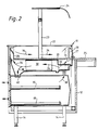
- Figure 2 is a section on the line II - II in Fig. 1;
- Figure 3 is a further diagrammatic section illustrating the position of various functional units; and
- Figure 4 is a simplified block circuit diagram of the electronic control system.
- As shown in Figs. 1, 2 and 3, a refrigerated
display unit 10 comprises acabinet 12 mounted onfeet 14 and having two refrigeratedstorage drawers display tray 20, supportingfood 21, and atransparent frame 22. Above thetray 20 there is supported by pillars 23 acanopy 24, and on the front of thecabinet 12 is mounted atray counter 25. Thedisplay tray 20 has anair inlet 26 and anair outlet 27, near which is located abaffle plate 28. - Mounted below the
display tray 20 is anevaporator 30, of the coil type, connected to arefrigeration condensing unit 31 which is accessible for cleaning via a drop-down louvredair intake 32, and which can be easily pulled out of thecabinet 12 for service. Access to a condensate drip tray (not shown) is gained through a hingedpanel 33. - Air in a closed circuit passes through a
centrifugal fan 36, upstream of theevaporator 30, through theevaporator 30, over the display tray 20 and back to thefan 36, as indicated byarrows 34. Thebaffle plate 28 allows cold air in the display tray to build up to a predetermined height. A branch stream is driven downwardly over thedrawers fan 40 downstream of theevaporator 30, as indicated byarrows 38. Above thefan 40 is positioned a guard (not shown) to prevent food being placed immediately thereabove and thus stopping the circulation of air to thedrawers 16. Ahumidification unit 42 is arranged to inject a fine mist of softened water into the air leaving theevaporator 30. - The electronic control system illustrated in Fig. 3 is largely centralised in an electronic control unit 44 (see Fig. 2) and also includes an air
inlet temperature sensor 46 and an airoutlet temperature sensor 48 for sensing the air temperatures at theinlet 26 and theoutlet 27 of the display compartment. An associateddisplay 52 displays the mean of the inlet and outlet temperatures as computed by thecomparator 49 to give the temperature approximately at the mid-point 50. Arelative humidity sensor 54 is arranged to give an RH read-out also on thedisplay 52. Moreover, the control system is arranged to control the speed of thefans compressor 59; and also the defrost cycles throughsensors 56,58,comparator 60 anddefrost selector 62. Additionally, the control system controls thehumidifier 42 and its associated water treatment systems, and cabinet lighting. - By monitoring the computed mid-point temperature to ± 0.1°C the control system enables the temperature range at the rear of the
tray 20 to be controlled to ± 1.5°C; at the middle to ± 1°C; and better than ± 2°C at the front. Moreover, the control system allows a choice of mid-point temperatures of + 5 or + 8°C, and a choice of humidity settings up to 85% RH. - From the foregoing it will be appreciated that the above-described refrigerated
display unit 10 offers a wide variety of improvements over existing units, in particular the capability of maintaining a large open food display at a temperature not exceeding + 5°C over the height of the food.
Claims (7)
- Apparatus for displaying material (21) under refrigerated conditions, comprising a display compartment (20,22), refrigeration means (30,31,36) for generating a stream (34) of cooled air which passes through the display compartment (20,22), an air inlet sensor (46) for sensing the temperature of the air at the inlet (26) to the display compartment (20,22), an air outlet sensor (48) for sensing the temperature of the air at the outlet (27) from the display compartment (20,22), and control means (44) for controlling the operation of the refrigeration means (30,31, 36), characterised in that the control means (44) is responsive to a signal derived from the output of both the sensors (46,48), thereby maintaining the air temperature in the display compartment (20,22) within a narrow predetermined range.
- Apparatus according to claim 1, in which the control means (44) is responsive to the computed mean of the temperatures at the inlet (26) and the outlet (27) of the display compartment (20,22).
- Apparatus according to claim 3, in which the fan (36) is a centrifugal fan which is located upstream of the evaporator (30).
- Apparatus according to claim 2 or 3, in which there is a further fan (40) downstream of the evaporator (30) to drive a refrigerated airsteam (38) to a refrigerated storage compartment (16,18).
- Apparatus according to any preceding claim, in which the evaporator (30) has a large surface area, allowing it to be operated at a temperature such that moisture is retained in the air stream (34).
- Apparatus according to claim 5, in which the surface area of the evaporator exceeds more than about 10.3 m² per metre run.
- Apparatus according to any preceding claim, in which continuous humidification means (42) lie downstream of the refrigeration means (30,32,36) and are arranged to inject a fine fresh water mist into the air stream.
Applications Claiming Priority (3)
| Application Number | Priority Date | Filing Date | Title |
|---|---|---|---|
| GB9001225 | 1990-01-19 | ||
| GB909001225A GB9001225D0 (en) | 1990-01-19 | 1990-01-19 | Refrigerated food display apparatus |
| PCT/GB1991/000078 WO1991010388A1 (en) | 1990-01-19 | 1991-01-18 | Apparatus for displaying material under refrigerated conditions |
Publications (2)
| Publication Number | Publication Date |
|---|---|
| EP0511251A1 EP0511251A1 (en) | 1992-11-04 |
| EP0511251B1 true EP0511251B1 (en) | 1995-09-13 |
Family
ID=10669561
Family Applications (1)
| Application Number | Title | Priority Date | Filing Date |
|---|---|---|---|
| EP91902133A Expired - Lifetime EP0511251B1 (en) | 1990-01-19 | 1991-01-18 | Apparatus for displaying material under refrigerated conditions |
Country Status (5)
| Country | Link |
|---|---|
| US (1) | US5317881A (en) |
| EP (1) | EP0511251B1 (en) |
| DE (1) | DE69113022T2 (en) |
| GB (1) | GB9001225D0 (en) |
| WO (1) | WO1991010388A1 (en) |
Families Citing this family (13)
| Publication number | Priority date | Publication date | Assignee | Title |
|---|---|---|---|---|
| FR2756622B1 (en) * | 1996-12-04 | 1999-02-12 | Vachez Isabelle | DEVICE FOR HOLDING FOODS IN COLD ATMOSPHERE AND TABLE COMPRISING SUCH A DEVICE |
| US6564569B1 (en) | 2000-09-22 | 2003-05-20 | Brian D. Havens | Refrigeration system for commercial food handling |
| DE10105245A1 (en) * | 2001-02-06 | 2002-08-08 | Linde Ag | Measuring device for recording the cooling effect of a product presentation piece of furniture |
| US20050097910A1 (en) * | 2003-11-12 | 2005-05-12 | Sanden Corporation | Open showcase |
| US20050103212A1 (en) * | 2003-11-13 | 2005-05-19 | Eastern Tabletop Manufacturing Company, Inc. | Apparatus and method for presenting, serving and protecting food and beverages |
| US7367197B1 (en) * | 2004-09-03 | 2008-05-06 | H & K Dallas, Inc. | Refrigerated open condiment rail |
| AT500980B1 (en) | 2004-11-05 | 2007-01-15 | Doczekal Gerhard Ing | METHOD FOR MAINTAINING FOODSTUFFS AND PRESENTING RULES FOR FOODSTUFFS |
| US7367198B2 (en) * | 2005-07-07 | 2008-05-06 | Hussmann Corporation | Method of control for a refrigerated merchandiser |
| EP2478798A1 (en) * | 2011-01-25 | 2012-07-25 | Franz Hilberer | Device for cooling food |
| US10646054B2 (en) * | 2016-03-31 | 2020-05-12 | Panasonic Intellectual Property Management Co., Ltd. | Showcase and operation method thereof |
| US20190038047A1 (en) * | 2017-08-04 | 2019-02-07 | Nelson Chi | Controlled Atmosphere Storage Case |
| GB2584613B (en) * | 2019-05-16 | 2023-02-22 | Aerofoil Energy Ltd | Process for optimising the position of refrigerator air guides in order to achieve increased energy efficiency of the refrigerator |
| US11215598B2 (en) * | 2019-04-26 | 2022-01-04 | METER Group, Inc. USA | Meat processing sensor suite |
Family Cites Families (10)
| Publication number | Priority date | Publication date | Assignee | Title |
|---|---|---|---|---|
| US2794325A (en) * | 1956-03-13 | 1957-06-04 | Gen Motors Corp | Refrigerated display case |
| US3018712A (en) * | 1958-05-12 | 1962-01-30 | Honeywell Regulator Co | Control system for a room closing air curtain |
| US2932955A (en) * | 1958-12-31 | 1960-04-19 | Schaefer Inc | Gravity-flow open-topped refrigerated display cabinet |
| US3119241A (en) * | 1962-09-17 | 1964-01-28 | Recold Corp | Refrigerated display and storage fixture |
| US3698205A (en) * | 1971-10-07 | 1972-10-17 | Clark Equipment Co | Walk-in cooler refrigerated display case combination |
| US4117698A (en) * | 1977-06-29 | 1978-10-03 | Kysor Industrial Corporation | Refrigerated display |
| DE2923611A1 (en) * | 1979-06-11 | 1980-12-18 | Allg Kuehlmoebelbau Gmbh | Display cabinet for food - has separate temp. refrigeration and humidity controls for different sections holding different item |
| DK159004C (en) * | 1980-12-01 | 1991-01-28 | Knudsen Koeling A S | PROCEDURE FOR OPERATING A COOLING FURNITURE |
| US4738806A (en) * | 1985-08-08 | 1988-04-19 | Sanyo Electric Co., Ltd. | Humidifier for refrigeration showcase |
| US5007242A (en) * | 1988-09-30 | 1991-04-16 | Snow Brand Milk Products Co., Ltd. | Thermoelectric humidifier and display case provided with such humidifier |
-
1990
- 1990-01-19 GB GB909001225A patent/GB9001225D0/en active Pending
-
1991
- 1991-01-18 US US07/910,338 patent/US5317881A/en not_active Expired - Fee Related
- 1991-01-18 WO PCT/GB1991/000078 patent/WO1991010388A1/en active IP Right Grant
- 1991-01-18 DE DE69113022T patent/DE69113022T2/en not_active Expired - Fee Related
- 1991-01-18 EP EP91902133A patent/EP0511251B1/en not_active Expired - Lifetime
Also Published As
| Publication number | Publication date |
|---|---|
| DE69113022D1 (en) | 1995-10-19 |
| US5317881A (en) | 1994-06-07 |
| GB9001225D0 (en) | 1990-03-21 |
| WO1991010388A1 (en) | 1991-07-25 |
| DE69113022T2 (en) | 1996-02-01 |
| EP0511251A1 (en) | 1992-11-04 |
Similar Documents
| Publication | Publication Date | Title |
|---|---|---|
| EP0511251B1 (en) | Apparatus for displaying material under refrigerated conditions | |
| US5048303A (en) | Open front refrigerated display case with improved ambient air defrost means | |
| US3186185A (en) | Refrigerated display unit | |
| US4145893A (en) | Diversion defrost display cabinet | |
| US3063253A (en) | Low temperature refrigerated case | |
| US6343477B1 (en) | Refrigerator food storage temperature control system | |
| US7137438B2 (en) | Storage device | |
| US6145327A (en) | Air curtain for open-fronted, refrigerated showcase | |
| US4250955A (en) | Self-service replenishable food cabinet | |
| US3696630A (en) | Humidified and refrigerated showcase | |
| US4265092A (en) | Refrigerated display case using air defrost with supplemental heater | |
| US2810267A (en) | Refrigerated display case | |
| US9456705B2 (en) | Dual temperature refrigerated merchandiser | |
| US3091942A (en) | Food merchandiser | |
| US4347710A (en) | Glass door merchandizer with tertiary air band | |
| US4449374A (en) | Combination hot gas and air defrost refrigerated display case | |
| US5315837A (en) | Process for supplying cold to an open refrigerated enclosure for display and sale of fresh products in a supermarket | |
| KR100443317B1 (en) | Refrigeration showcase | |
| CA1068921A (en) | Diversion defrost display cabinet | |
| US3872683A (en) | Refrigeration defrost system | |
| US2962872A (en) | Refrigerator construction and controls | |
| CN207471874U (en) | Vertical freezer | |
| EP0065555B1 (en) | A method in the operation of a refrigerated display unit | |
| US4061482A (en) | Cooling coil and air distribution system defrost means | |
| US2180071A (en) | Refrigerator |
Legal Events
| Date | Code | Title | Description |
|---|---|---|---|
| PUAI | Public reference made under article 153(3) epc to a published international application that has entered the european phase |
Free format text: ORIGINAL CODE: 0009012 |
|
| 17P | Request for examination filed |
Effective date: 19920724 |
|
| AK | Designated contracting states |
Kind code of ref document: A1 Designated state(s): DE GB |
|
| 17Q | First examination report despatched |
Effective date: 19940909 |
|
| GRAA | (expected) grant |
Free format text: ORIGINAL CODE: 0009210 |
|
| AK | Designated contracting states |
Kind code of ref document: B1 Designated state(s): DE GB |
|
| REF | Corresponds to: |
Ref document number: 69113022 Country of ref document: DE Date of ref document: 19951019 |
|
| PG25 | Lapsed in a contracting state [announced via postgrant information from national office to epo] |
Ref country code: GB Effective date: 19960118 |
|
| PLBE | No opposition filed within time limit |
Free format text: ORIGINAL CODE: 0009261 |
|
| STAA | Information on the status of an ep patent application or granted ep patent |
Free format text: STATUS: NO OPPOSITION FILED WITHIN TIME LIMIT |
|
| 26N | No opposition filed | ||
| GBPC | Gb: european patent ceased through non-payment of renewal fee |
Effective date: 19960118 |
|
| PG25 | Lapsed in a contracting state [announced via postgrant information from national office to epo] |
Ref country code: DE Effective date: 19961001 |