EP0509840A2 - Générateur de son - Google Patents
Générateur de son Download PDFInfo
- Publication number
- EP0509840A2 EP0509840A2 EP92303491A EP92303491A EP0509840A2 EP 0509840 A2 EP0509840 A2 EP 0509840A2 EP 92303491 A EP92303491 A EP 92303491A EP 92303491 A EP92303491 A EP 92303491A EP 0509840 A2 EP0509840 A2 EP 0509840A2
- Authority
- EP
- European Patent Office
- Prior art keywords
- sounder
- plate
- housing
- assembly according
- unit
- Prior art date
- Legal status (The legal status is an assumption and is not a legal conclusion. Google has not performed a legal analysis and makes no representation as to the accuracy of the status listed.)
- Granted
Links
Images

Classifications
-
- G—PHYSICS
- G10—MUSICAL INSTRUMENTS; ACOUSTICS
- G10K—SOUND-PRODUCING DEVICES; METHODS OR DEVICES FOR PROTECTING AGAINST, OR FOR DAMPING, NOISE OR OTHER ACOUSTIC WAVES IN GENERAL; ACOUSTICS NOT OTHERWISE PROVIDED FOR
- G10K9/00—Devices in which sound is produced by vibrating a diaphragm or analogous element, e.g. fog horns, vehicle hooters or buzzers
- G10K9/18—Details, e.g. bulbs, pumps, pistons, switches or casings
- G10K9/20—Sounding members
-
- G—PHYSICS
- G08—SIGNALLING
- G08B—SIGNALLING SYSTEMS, e.g. PERSONAL CALLING SYSTEMS; ORDER TELEGRAPHS; ALARM SYSTEMS
- G08B3/00—Audible signalling systems, e.g. audible personal calling systems
Definitions
- the present invention relates to a sounding device, e.g. for a fire alarm, and in particular to a compact sounding device for inclusion in an alarm unit including a light and/or a sensor and/or a switch.
- the present invention provides a sounder assembly which comprises a body having an outer surface, sounder means located generally within the body, an opening in said surface to allow passage of sound from the sounder means, and a sounder plate mounted to said body so as to confront said opening and be spaced from said surface so that sound can emerge laterally of said plate.
- the sounding plate is spaced from the adjacent surface of the sounder housing, so that the volume of air between the sounding plate and the adjacent surface of the sounder housing acts as a resonating volume.
- the sounder plate may have a device, e.g. a sensor and/or a warning light, fixed or removably mounted to it.
- a device e.g. a sensor and/or a warning light
- the invention may provide an alarm assembly which comprises a sounder assembly as defined in the first aspect above, and a device, e.g. a sensor coupled to the sounder for actuation thereof and/or an alarm light, that may be arranged to be actuated simultaneously with the sounder; said device being mounted on the sounder plate.
- the sounder unit is normally between the detector unit (or light unit) and the surface on which the sounder assembly is to be mounted, since it is important that the detector is exposed to the ambient air, and that the light is visible. Therefore, more consideration was given to the design of the sounder unit.
- the centre of the sounder be displaced from the centre of the sounder housing.
- the sounder may be displaced so that its periphery is proximate the centre of the sounder housing, and indeed it is possible for the sounder to be displaced so that the centre of the sounder housing is (in plan) outside the circumference of the sounder.
- the sounder is mounted such that at least a part projects through an opening in the sounder housing towards the sounder plate, so that a surface of the sounder is close to the sounding plate itself.
- a slight adjustment of the spacing of the sounding plate and the sounder housing must then be made, in order to ensure that the volume therebetween (excluding the projecting part of the sounder) is suitable to achieve a satisfactory resonance, but in practice the level of adjustment is small.
- this development of the present invention has the advantage that the overall height of the sounder unit may be reduced, since the height of the sounder housing may be less than the total height of the sounder itself.
- sounder housings have been at least as high, if not higher, than the height of the sounder.
- a terminal block be provided within the sounder housing, providing for electrical connection both to the sounder and to the detector/light unit. There may then be an opening in the housing in the surface of the housing closest to the detector/light unit, to permit suitable electrical connection. Again, this permits a compact construction to be achieved.
- the present invention has primarily been developed for a ceiling mounted sounder assembly, it is not restricted thereto and the sounder assembly may be mounted on any suitable surface.
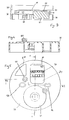
- Fig. 1 shows a generally cylindrical sounder body 2, generally inside which is an electrical sounder 4 (best seen in Fig. 2). The sound from the sounder is emitted through an opening 6 in the top face 5 of the sounder body.
- a sounder plate 8 is shaped and dimensioned to overlie the top face 5 of the sounder body 2, to which it is mounted.
- a number of fixing holes 10 may pass through the plate 8 and the spacers 12.
- Fig. 2 shows the bottom of the sounder body 2, generally inside which is the sounding device 4.
- Said sounding device has a number of electrical connectors, 14.
- the sounder body may have a rim 16 bridged by strengthening walls 18, and contain an encapsulating resin in which the sounder 4 is embedded.
- sound from the sounding device 4 is emitted through the opening 6 and emerges radially from the space between the body 2 and the plate 8.
- An associated component e.g. a fire detector or a flashing xenon light may be mounted on the plate, thus providing a compact alarm unit.
- the dimensions of the components are important, particularly the diameter of the opening 6, the diameter of the plate 8 and its spacing from the body 2. For example, if the spacing is increased, the plate diameter should be decreased.
- Fig. 3 shows a second embodiment of the present invention in which a detector unit 20 and a sounder unit 21 are stacked one on the other.
- the detector unit 20 may be wholly conventional and therefore its detailed structure will not be discussed.
- the sounder unit 21 comprises a housing 22 which supports a sounder 23, a sounding plate 24 connected to the housing via supports 25 and a terminal block 26.
- the sounder unit 21 may also contain suitable electronics, as will be discussed later.
- the sounder 23 in Fig. 3 is laterally displaced from the centre of the housing 22, so that the terminal block 26 may be mounted alongside the sounder 23.
- the terminal block 26 is mounted in the housing 22 so that it is (in plan) within the boundaries of an aperture 27 (shown more clearly in Fig. 5) so that electrical connections arriving at the sounder assembly from the bottom in Fig. 3 may pass through the housing 22 via the terminal block 26 to the detector 20.
- An opening 28 may be provided in the sounding plate 24 to facilitate this.
- the sounder 23 projects from the housing 22 into the space defined between the housing 22 and the sounding plate 24.
- the upper surface 29 of the sounder (from an opening in which surface 29 the sound is emitted), is very close to the sounding plate 24.
- the spacing is preferably at least as small as 3 mm, more preferably 1 mm.
- the volume of air between the sounding plate 24 and the adjacent surface of the housing 22 acts as a resonating volume for the sounder 23, and, since the sounder 23 projects into that space, the spacing of the sounding plate 24 and the housing 22 must be suitably selected in order to achieve the necessary resonant volume.
- Fig. 4 shows the structure of the housing 22 in more detail; Fig. 4 being taken along the line B to B in Fig. 5.
- Fig. 4 shows that the housing 22 has a boss 40 projecting from its upper surface, which boss may coincide with an opening in the sounding plate 24 to enable connection thereto of a suitable interconnection to the detector unit 20. In this way, the detector unit 20 is fixed above the sounder unit 21.
- Fig. 4 also shows a mounting recess 41 in the housing 22 to enable the housing 22 and hence the sounder assembly, to be fixed to a suitable surface.
- Fig. 5 shows that a second mounting recess 42 similar to the mounting recess 41 may be provided.
- FIG. 5 shows the upper surface of the sounder unit 21 in plan view.
- the mounting of the terminal block 26 below the aperture 27 can clearly be seen.
- Fig. 5 shows that there is a suitable space, e..g area 50 to enable electronic components to be mounted in the housing 22 to control the sounder and/or detector.
- the electronics mounted in the space 50 may be conventional, and will not be discussed in detail.
- a user controllable adjustment device 51 connected via the electronics in e.g. space 50 to the sounder 23 for controlling the volume of the sounder 23. The mounting of this in line with the aperture 27 makes access for adjustment easy.
- a further feature that is evident from Fig. 5 is that the aperture 27 is larger than the terminal block 26, to allow the passage of a suitable number of cables to or from the detector unit 20.
- the sounder assembly has the minimum lateral extent, and also the minimum vertical extent compatible with the size of the components. This is particularly desirably in a ceiling mounted assembly, since then the assembly is not obtrusive. It should be noted that, when the assembly of Fig. 3 is mounted on the ceiling, it will be inverted and the words "above” and “below” in the description of the embodiment are concerned only with the orientation shown in Fig. 3. It may also be noted that the sounder assembly according to that embodiment may be mounted on any suitable surface at any orientation.
- the detector unit 20 it is possible to replace the detector unit 20 with a light unit, with the sounder unit then being connected to a remote detector. Again, such a light unit may be conventional.
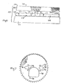
- Figs. 6 and 7 show a third embodiment which is a sounder unit 50 substantially the same as the sounder unit 21 of the second embodiment.
- a housing 51 in which a sounder, a terminal block 52, and other components are mounted; and there is a sounding plate 54 which, in use, is connected to the housing via supports 56.
- the main top surface 58 of the housing is a circular plate. Adjacent the periphery there is a circular rib 60.
- the terminal block 52 is mounted in an aperture delimited by a wall 62 that rises from the surface to the same height as the supports 56. Also projecting above the surface 58 to the same height are a pair of hollow bosses 64, similar to the bosses 40 of the second embodiment.
- the sounder projects slightly above the surface 58 within a sounder cover 66.
- the top of this cover is an annular plate 68 with a central opening, centered over the sounder.
- the plate 68 is spaced slightly below the level of the tops of the terminal block wall 62, the supports 56 and the bosses 64.
- a pillar 69 that also extends to the higher level.
- the sounding plate 54 has the form of a shallow cup.
- the base 70 is a flat disc penetrated by screw apertures 72 corresponding to the supports 56; by connection apertures 74 corresponding to the hollow interiors of the bosses 64; an adjustment aperture 76 for permitting access to a user controllable device associated with the sounder; and a large terminal block aperture 78 corresponding to the aperture delimited by the wall 62.
- the cylinder wall 80 has the form of a multiplicity of teeth 82 between which are defined openings. Over about two thirds of the circumference these penetrate the wall 80 to provide sound outlets. Over the remaining third they are closed.
- the plate is dimensioned so that it can sit on the housing 51, engaging over the rib 60.
- the base 70 is then in contact with the tops of the terminal block wall 62, the supports 56, the bases 64, and the pillar 69, and is spaced by a small, carefully controlled, distance from the plate 68 of the sounder cover 66, thus providing a predetermined resonance volume.
- the plate 54 With the various openings in register, the plate 54 is oriented so that the closed third of the openings are centred on, and adjacent, the sounder cover 66.
Landscapes
- Physics & Mathematics (AREA)
- Engineering & Computer Science (AREA)
- Acoustics & Sound (AREA)
- Multimedia (AREA)
- General Physics & Mathematics (AREA)
- Electrophonic Musical Instruments (AREA)
- Percussion Or Vibration Massage (AREA)
- Fire Alarms (AREA)
- Headphones And Earphones (AREA)
- Eye Examination Apparatus (AREA)
- Telephone Function (AREA)
- Measuring Pulse, Heart Rate, Blood Pressure Or Blood Flow (AREA)
Applications Claiming Priority (4)
| Application Number | Priority Date | Filing Date | Title |
|---|---|---|---|
| GB919108417A GB9108417D0 (en) | 1991-04-19 | 1991-04-19 | Sounding device |
| GB9108417 | 1991-04-19 | ||
| GB919122437A GB9122437D0 (en) | 1991-10-23 | 1991-10-23 | Sounder assembly |
| GB9122437 | 1991-10-23 |
Publications (3)
| Publication Number | Publication Date |
|---|---|
| EP0509840A2 true EP0509840A2 (fr) | 1992-10-21 |
| EP0509840A3 EP0509840A3 (en) | 1993-02-24 |
| EP0509840B1 EP0509840B1 (fr) | 1996-06-26 |
Family
ID=26298757
Family Applications (1)
| Application Number | Title | Priority Date | Filing Date |
|---|---|---|---|
| EP92303491A Expired - Lifetime EP0509840B1 (fr) | 1991-04-19 | 1992-04-16 | Générateur de son |
Country Status (4)
| Country | Link |
|---|---|
| EP (1) | EP0509840B1 (fr) |
| AT (1) | ATE139855T1 (fr) |
| DE (1) | DE69211753T2 (fr) |
| ES (1) | ES2088544T3 (fr) |
Cited By (3)
| Publication number | Priority date | Publication date | Assignee | Title |
|---|---|---|---|---|
| WO1998038608A1 (fr) * | 1997-02-27 | 1998-09-03 | Fulleon Limited | Sonneur |
| EP1881470A4 (fr) * | 2005-05-10 | 2009-03-04 | Hochiki Co | Dispositif de sortie d alarme |
| AU2011203306B2 (en) * | 2005-05-10 | 2011-11-03 | Hochiki Corporation | Sounder |
Family Cites Families (2)
| Publication number | Priority date | Publication date | Assignee | Title |
|---|---|---|---|---|
| FR2267602A1 (en) * | 1974-04-09 | 1975-11-07 | Seima | Resonator plate for motor vehicle horn - has diameter greater than that of vibrating membrane |
| DE3214074A1 (de) * | 1982-04-16 | 1983-10-20 | Marukokeihouki Co. Ltd., Nagano | Elektrische hupe |
-
1992
- 1992-04-16 AT AT92303491T patent/ATE139855T1/de not_active IP Right Cessation
- 1992-04-16 EP EP92303491A patent/EP0509840B1/fr not_active Expired - Lifetime
- 1992-04-16 ES ES92303491T patent/ES2088544T3/es not_active Expired - Lifetime
- 1992-04-16 DE DE69211753T patent/DE69211753T2/de not_active Expired - Lifetime
Cited By (6)
| Publication number | Priority date | Publication date | Assignee | Title |
|---|---|---|---|---|
| WO1998038608A1 (fr) * | 1997-02-27 | 1998-09-03 | Fulleon Limited | Sonneur |
| US6362726B1 (en) | 1997-02-27 | 2002-03-26 | Fulleon Limited | Sounder device which deflects sound away from a housing |
| EP1881470A4 (fr) * | 2005-05-10 | 2009-03-04 | Hochiki Co | Dispositif de sortie d alarme |
| EP2175433A3 (fr) * | 2005-05-10 | 2011-03-30 | Hochiki Corporation | Système d'alarme incendie |
| AU2011203306B2 (en) * | 2005-05-10 | 2011-11-03 | Hochiki Corporation | Sounder |
| US8125320B2 (en) | 2005-05-10 | 2012-02-28 | Hochiki Corporation | Fire alarm system |
Also Published As
| Publication number | Publication date |
|---|---|
| DE69211753D1 (de) | 1996-08-01 |
| DE69211753T2 (de) | 1996-11-07 |
| EP0509840A3 (en) | 1993-02-24 |
| ATE139855T1 (de) | 1996-07-15 |
| EP0509840B1 (fr) | 1996-06-26 |
| ES2088544T3 (es) | 1996-08-16 |
Similar Documents
| Publication | Publication Date | Title |
|---|---|---|
| US4893062A (en) | Wall box dimming system and face plate and switch assembly therefor | |
| EP1368593B1 (fr) | Ameliorations apportees a des detecteurs de fumee et ameliorations associees a des detecteurs de fumee | |
| US6204602B1 (en) | Compact fluorescent lamp and ballast assembly with an air gap for thermal isolation | |
| US5030893A (en) | Wall box dimming system and face plate and switch assembly therefor | |
| JPH04322052A (ja) | 電子医療器具をバッテリ駆動操作するためのバッテリパック及びその製造方法 | |
| US6057778A (en) | Modular interchangeble cover system | |
| AU2002247823A1 (en) | Improvements in and relating to smoke detectors | |
| US4700079A (en) | Light-transmission type smoke detector having a spiral optical path | |
| JPH0215221Y2 (fr) | ||
| EP0509840B1 (fr) | Générateur de son | |
| US4306229A (en) | Smoke detector having an integral piezo-electric buzzer | |
| EP0482886A1 (fr) | Dispositif acoustique pour jouets | |
| US6362726B1 (en) | Sounder device which deflects sound away from a housing | |
| CA2270984C (fr) | Les alarmes | |
| US4032707A (en) | Housing for battery-operated device | |
| US6097300A (en) | Multifunctional sensing and control assembly | |
| EP0691773A2 (fr) | Module de support d'un transducteur acoustique et de composants d'un circuit imprimé, insérable dans la partie réceptrice d'un appareil de test pour le technicien | |
| US20080247125A1 (en) | Handheld Housing for Wall-Mount Controller | |
| US4464792A (en) | Portable transmitter enclosure | |
| EP0841673A2 (fr) | Module de commutation électrique | |
| US5652698A (en) | Bracket assembly for a circuit breaker and an associated method | |
| JPH09373U (ja) | 火災感知器 | |
| JP2011113541A (ja) | 火災検知器 | |
| CN219814729U (zh) | 内置药盒的保温茶杯 | |
| JP3532070B2 (ja) | 充電器 |
Legal Events
| Date | Code | Title | Description |
|---|---|---|---|
| PUAI | Public reference made under article 153(3) epc to a published international application that has entered the european phase |
Free format text: ORIGINAL CODE: 0009012 |
|
| AK | Designated contracting states |
Kind code of ref document: A2 Designated state(s): AT BE CH DE DK ES FR GB GR IT LI LU MC NL PT SE |
|
| PUAL | Search report despatched |
Free format text: ORIGINAL CODE: 0009013 |
|
| AK | Designated contracting states |
Kind code of ref document: A3 Designated state(s): AT BE CH DE DK ES FR GB GR IT LI LU MC NL PT SE |
|
| 17P | Request for examination filed |
Effective date: 19930316 |
|
| RAP1 | Party data changed (applicant data changed or rights of an application transferred) |
Owner name: FULLEON LIMITED |
|
| RAP3 | Party data changed (applicant data changed or rights of an application transferred) |
Owner name: FULLEON SYNCHROBELL LIMITED |
|
| 17Q | First examination report despatched |
Effective date: 19950209 |
|
| GRAH | Despatch of communication of intention to grant a patent |
Free format text: ORIGINAL CODE: EPIDOS IGRA |
|
| GRAA | (expected) grant |
Free format text: ORIGINAL CODE: 0009210 |
|
| AK | Designated contracting states |
Kind code of ref document: B1 Designated state(s): AT BE CH DE DK ES FR GB GR IT LI LU MC NL PT SE |
|
| PG25 | Lapsed in a contracting state [announced via postgrant information from national office to epo] |
Ref country code: BE Effective date: 19960626 Ref country code: GR Free format text: LAPSE BECAUSE OF FAILURE TO SUBMIT A TRANSLATION OF THE DESCRIPTION OR TO PAY THE FEE WITHIN THE PRESCRIBED TIME-LIMIT Effective date: 19960626 Ref country code: AT Effective date: 19960626 Ref country code: NL Free format text: LAPSE BECAUSE OF FAILURE TO SUBMIT A TRANSLATION OF THE DESCRIPTION OR TO PAY THE FEE WITHIN THE PRESCRIBED TIME-LIMIT Effective date: 19960626 Ref country code: DK Effective date: 19960626 |
|
| REF | Corresponds to: |
Ref document number: 139855 Country of ref document: AT Date of ref document: 19960715 Kind code of ref document: T |
|
| REG | Reference to a national code |
Ref country code: ES Ref legal event code: BA2A Ref document number: 2088544 Country of ref document: ES Kind code of ref document: T3 |
|
| REG | Reference to a national code |
Ref country code: CH Ref legal event code: NV Representative=s name: MICHELI & CIE INGENIEURS-CONSEILS |
|
| REF | Corresponds to: |
Ref document number: 69211753 Country of ref document: DE Date of ref document: 19960801 |
|
| REG | Reference to a national code |
Ref country code: ES Ref legal event code: FG2A Ref document number: 2088544 Country of ref document: ES Kind code of ref document: T3 |
|
| ITF | It: translation for a ep patent filed | ||
| PG25 | Lapsed in a contracting state [announced via postgrant information from national office to epo] |
Ref country code: SE Effective date: 19960926 Ref country code: PT Effective date: 19960926 |
|
| ET | Fr: translation filed | ||
| NLV1 | Nl: lapsed or annulled due to failure to fulfill the requirements of art. 29p and 29m of the patents act | ||
| PG25 | Lapsed in a contracting state [announced via postgrant information from national office to epo] |
Ref country code: LU Free format text: LAPSE BECAUSE OF NON-PAYMENT OF DUE FEES Effective date: 19970430 |
|
| PLBE | No opposition filed within time limit |
Free format text: ORIGINAL CODE: 0009261 |
|
| STAA | Information on the status of an ep patent application or granted ep patent |
Free format text: STATUS: NO OPPOSITION FILED WITHIN TIME LIMIT |
|
| 26N | No opposition filed | ||
| PG25 | Lapsed in a contracting state [announced via postgrant information from national office to epo] |
Ref country code: MC Effective date: 19971031 |
|
| REG | Reference to a national code |
Ref country code: CH Ref legal event code: PFA Free format text: FULLEON SYNCHROBELL LIMITED TRANSFER- FULLEON LIMITED |
|
| REG | Reference to a national code |
Ref country code: FR Ref legal event code: CA Ref country code: FR Ref legal event code: CD |
|
| REG | Reference to a national code |
Ref country code: ES Ref legal event code: PC2A |
|
| REG | Reference to a national code |
Ref country code: GB Ref legal event code: IF02 |
|
| PGFP | Annual fee paid to national office [announced via postgrant information from national office to epo] |
Ref country code: FR Payment date: 20110331 Year of fee payment: 20 Ref country code: CH Payment date: 20110328 Year of fee payment: 20 |
|
| PGFP | Annual fee paid to national office [announced via postgrant information from national office to epo] |
Ref country code: ES Payment date: 20110425 Year of fee payment: 20 Ref country code: DE Payment date: 20110429 Year of fee payment: 20 Ref country code: GB Payment date: 20110328 Year of fee payment: 20 |
|
| PGFP | Annual fee paid to national office [announced via postgrant information from national office to epo] |
Ref country code: IT Payment date: 20110423 Year of fee payment: 20 |
|
| REG | Reference to a national code |
Ref country code: DE Ref legal event code: R071 Ref document number: 69211753 Country of ref document: DE |
|
| REG | Reference to a national code |
Ref country code: DE Ref legal event code: R071 Ref document number: 69211753 Country of ref document: DE |
|
| REG | Reference to a national code |
Ref country code: CH Ref legal event code: PL |
|
| REG | Reference to a national code |
Ref country code: GB Ref legal event code: PE20 Expiry date: 20120415 |
|
| PG25 | Lapsed in a contracting state [announced via postgrant information from national office to epo] |
Ref country code: DE Free format text: LAPSE BECAUSE OF EXPIRATION OF PROTECTION Effective date: 20120417 |
|
| PG25 | Lapsed in a contracting state [announced via postgrant information from national office to epo] |
Ref country code: GB Free format text: LAPSE BECAUSE OF EXPIRATION OF PROTECTION Effective date: 20120415 |
|
| REG | Reference to a national code |
Ref country code: ES Ref legal event code: FD2A Effective date: 20130717 |
|
| PG25 | Lapsed in a contracting state [announced via postgrant information from national office to epo] |
Ref country code: ES Free format text: LAPSE BECAUSE OF EXPIRATION OF PROTECTION Effective date: 20120417 |