EP0509646A1 - Reduced pressure heat treating device - Google Patents
Reduced pressure heat treating device Download PDFInfo
- Publication number
- EP0509646A1 EP0509646A1 EP92302380A EP92302380A EP0509646A1 EP 0509646 A1 EP0509646 A1 EP 0509646A1 EP 92302380 A EP92302380 A EP 92302380A EP 92302380 A EP92302380 A EP 92302380A EP 0509646 A1 EP0509646 A1 EP 0509646A1
- Authority
- EP
- European Patent Office
- Prior art keywords
- heat exchanger
- heat
- reduced pressure
- ejector
- treating device
- Prior art date
- Legal status (The legal status is an assumption and is not a legal conclusion. Google has not performed a legal analysis and makes no representation as to the accuracy of the status listed.)
- Granted
Links
- 238000010438 heat treatment Methods 0.000 claims abstract description 12
- 239000012530 fluid Substances 0.000 claims description 3
- 230000009467 reduction Effects 0.000 claims description 3
- 230000001737 promoting effect Effects 0.000 claims description 2
- XLYOFNOQVPJJNP-UHFFFAOYSA-N water Substances O XLYOFNOQVPJJNP-UHFFFAOYSA-N 0.000 abstract description 32
- 230000006872 improvement Effects 0.000 abstract description 3
- 239000000126 substance Substances 0.000 abstract description 3
- 239000000498 cooling water Substances 0.000 description 8
- 230000000694 effects Effects 0.000 description 5
- 239000007789 gas Substances 0.000 description 5
- 238000001816 cooling Methods 0.000 description 4
- 239000000463 material Substances 0.000 description 4
- 239000007788 liquid Substances 0.000 description 3
- 238000011176 pooling Methods 0.000 description 3
- 230000008859 change Effects 0.000 description 2
- 239000007795 chemical reaction product Substances 0.000 description 2
- 239000000047 product Substances 0.000 description 2
- 230000008901 benefit Effects 0.000 description 1
- 238000009833 condensation Methods 0.000 description 1
- 230000005494 condensation Effects 0.000 description 1
- 238000007599 discharging Methods 0.000 description 1
- 238000001704 evaporation Methods 0.000 description 1
- 230000008020 evaporation Effects 0.000 description 1
- 230000001788 irregular Effects 0.000 description 1
- 238000012423 maintenance Methods 0.000 description 1
- 230000004048 modification Effects 0.000 description 1
- 238000012986 modification Methods 0.000 description 1
- 238000011084 recovery Methods 0.000 description 1
- 230000001603 reducing effect Effects 0.000 description 1
- 230000035939 shock Effects 0.000 description 1
- 238000003756 stirring Methods 0.000 description 1
Images


Classifications
-
- F—MECHANICAL ENGINEERING; LIGHTING; HEATING; WEAPONS; BLASTING
- F28—HEAT EXCHANGE IN GENERAL
- F28F—DETAILS OF HEAT-EXCHANGE AND HEAT-TRANSFER APPARATUS, OF GENERAL APPLICATION
- F28F27/00—Control arrangements or safety devices specially adapted for heat-exchange or heat-transfer apparatus
-
- Y—GENERAL TAGGING OF NEW TECHNOLOGICAL DEVELOPMENTS; GENERAL TAGGING OF CROSS-SECTIONAL TECHNOLOGIES SPANNING OVER SEVERAL SECTIONS OF THE IPC; TECHNICAL SUBJECTS COVERED BY FORMER USPC CROSS-REFERENCE ART COLLECTIONS [XRACs] AND DIGESTS
- Y10—TECHNICAL SUBJECTS COVERED BY FORMER USPC
- Y10S—TECHNICAL SUBJECTS COVERED BY FORMER USPC CROSS-REFERENCE ART COLLECTIONS [XRACs] AND DIGESTS
- Y10S165/00—Heat exchange
- Y10S165/917—Pressurization and/or degassification
Definitions
- This invention relates to a heat treating device for safely and efficiently heat-treating product to be treated at relatively low temperature such as below 100 o C, using reduced pressure steam and/or water as heat media.
- this device includes a reaction vessel 1 for causing materials supplied from an inlet 5 to react as stirring them by a stirrer 7 and delivering reaction product from an outlet 9, a heat exchanger 11 of jacket type having an inlet 13 and an outlet 15 of a heat media such as steam and water and surrounding the vessel 1, a piping 17 for feeding heating steam to the heat exchanger 11 through an automatic valve 19, a suction pump 21 of ejector type having its suction port 23 connected to the outlet 15 of the heat exchanger 11 through a piping 24, a water tank 25 having a diffuser 27 of the ejector 21 connected to its upper space and being provided with level sensors 29a and 29b and a temperature sensor 31, a piping 33 for feeding cooling water to the water tank 25 through an automatic valve 35, a piping 37 for connecting a lower portion of the tank 25 to a jetting nozzle 41 of the ejector 21 through a pump 39, a piping 43 for connecting the piping 37 to the inlet 13 of the heat exchanger 11 through an automatic valve 45, a drain
- the valve 19 When the reaction vessel 1 is heated, the valve 19 is opened and the valve 45 is closed by a signal from the central control unit 51, and heating steam is supplied from the piping 17 to the heat exchanger 11. The steam is sucked by the ejector 21 to enter the water tank 25 together with condenced water, thereby raising the water temperature within the tank 25 gradually. Since the interior of the heat exchanger 11 is put in a reduced pressure state by the ejector 21, saturation temperature of the steam is low and the materials can be caused to react at a low temperature below 100 o C. In the case of turning from heating to cooling, the valve 19 is closed and the valve 45 is opened by a signal from the central control unit 51, and cool water is supplied into the tank 25, thereby lowering the water temperature within the tank 25 gradually.
- the reaction vessel 1 cooled with water whose temperature lowers gradually.
- the water temperature within the tank 25 is sensed by the temperature sensor 31 and the central control unit 51 responds thereto to control the valve 35, thereby controlling a change of the water temperature in accordance with a predetermined program to control a temperature change of the heat exchanger 11.
- the level sensors 29a and 29b sense the upper and lower limit of the water level, respectively, and the central control unit 51 responds thereto to control the valves 35 and 49 for maintaining the water level of the tank 25 substantially in constant.
- the temperature difference between the initial cooling water and the heating steam is small at the time of turning from heating to cooling and, therefore, it has such an advantage in that there is no hammering effect caused by thermal shock and a lifetime of the device can be extended.
- this device bears such a problem in that, although the reduced pressure level within the heat exchanger 11 must be precisely controlled for effecting a predetermined temperature control of the heat exchanger 11, water having condenced from the steam within the heat exchanger 11 at the time of heating or remained therein from evaporation at the time of cooling may pool in the vicinity of the outlet 15 to clog it up, thereby causing variation in the reduced pressure level and, accordingly, in the temperature, which results in variation in the quality of the reaction product. Moreover, it has also such a problem in that the water pooling in the vicinity of the outlet 15 actually makes it impossible to lower the heating temperature below 50 o C since it impedes pressure reduction within the heat exchanger 11.
- an object of this invention is to provide an improved device which can effect an effective heat treatment at a much lower temperature regardless of the above-mentioned water pooling, by adding a simple improvement to the above-mentioned prior art device.
- the above-mentioned object can be attained by connecting another sucking means to the upper portion of the heat exchanger of the prior art device to suck the remaining vapor in the upper portion of the heat exchanger aside from the ejector connected to the lower outlet of the heat exchanger.
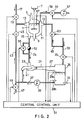
- FIG. 2 which shows an embodiment of this invention
- this embodiment is constructed by adding some components to the prior art device of FIG. 1. Since the same components as shown in FIG. 1 indeed effect substantially same function as described above, the description will not be made on these components but only on the additional components.
- a steam trap 53 and an automatic valve 55 are inserted in parallel in a piping 24 between a heat exchanger 11 and an ejector 21 and, as a feature of this invention, an evacuation pump 57 is connected through a piping 59 and an automatic valve 61 to a top portion of the heat exchanger 11.
- An inlet 13 of the heat exchanger 11 is further connected through an automatic valve 63 and a piping 65 to a cooling water supply piping 33.
- the inlet 33 opens throughout the periphery of the side wall of a reaction vessel 1 so that heat media such as steam and water are distributed uniformly throughout the periphery of its side wall.
- the reaction vessel 1 is provided with a temperature sensor 67 whose temperature signal is transferred to a central control unit 51.
- the valve 55 is closed to actuate the steam trap 53. Then, the condenced water is removed here and does not clog up the outlet 15 of the heat exchanger 11 and, therefore, the evacuation pump 57 is no longer needed.
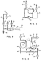
- FIG. 3 shows a variation in which an ejector 73 is used therefor. Since the gas within the heat exchanger 11 is mainly water vapor which may condence in the way of discharge, the ejector is preferable as the evacuation pump 57.
- the ejector 73 has its nozzle connected through an automatic valve 69 and a piping 71 to the steam supply piping 17 so as to be driven with steam. Also, it has a diffuser opening to the external air.
- FIG. 4 shows another variation in which two ejectors 74 and 75 are further connected in series to the ejector 73 of FIG. 3 in order to improve its evacuating power.
- the second ejector 74 has its nozzel connected through an automatic valve 77 to the piping 71 so as to be driven with steam, while the third ejectror 75 has its nozzle connected through an automatic valve 79 to the cooling water piping 33 so as to be driven with water flow.
- the diffusers of the first and second ejectors are connected respectively to the suction chambers of the succeeding ejectors and the diffuser of the third ejector is opened to the external air.
- FIG. 5 which shows a further variation, two series ejectors 73 and 74 are used and the diffuser of the second ejector 74 is connected to the suction chamber of the liquid sucking ejector 21 together with the piping 24 from the outlet of the heat exchanger 11, to recover condensation.
- the diffuser of the second ejector 74 is connected to the suction chamber of the liquid sucking ejector 21 together with the piping 24 from the outlet of the heat exchanger 11, to recover condensation.
- Such recovery of condenzation is often important when the heat medium is a substance other than water.
- the nozzle of the ejector 73 of FIG. 3 is connected to the outlet of the pump 39, thereby driving the ejector 73 with output fluid of the pump 39.
- the diffuser of the ejector 73 is connected to the tank 25 for recovering the driving fluid.
- the gas exhaust piping 59 is connected to the suction chamber of the ejector 21, so that the ejector 21 serves two functions at the same time.
- the ejector 21 has its nozzle connected through a piping 81 having an automatic valve 83 to the steam supply piping 17 to be driven with high pressure steam, in order to raise its sucking power.
- a steam stap 85 is inserted in the piping 81 so as to remove condenced water.
- FIG. 8 shows an improvement of the heat exchanger 11.
- the inlet 13 of the heat exchanger 11 is provided many nozzles 87 facing the side wall of the reaction vessel 1, so that cooling water is jetted against the side wall and caused to flow down uniformly along it to cool the vessel 1 efficiently.
- a nozzle 89 is also disposed in the lower portion of the heat exchanger 11 and connected to a compressed air supply (not shown) through a piping 91 having an automatic valve 93.
- the nozzle 89 serves to cause the air jetted therefrom to flow helically upwards within the heat exchamber 11 and be exhausted by the evacuation pump 57. With this structure, the temperature in the heat exchanger 11 is made uniform and any irregular cooling can be prevented.
- the heat exchanger 11 is not limited to the jacket type as shown and may be of any type suitable for applying the invention. While ejectors are used as a preferred embodiment of the suction pump means for discharging liquids and gases, any type having a suitable sucking power may be used therefor. Although water and its vapor are used as the heat media, other known materials may be used in accordance with the treating conditions. Moreover, part of the automatic valves as shown may be manually operated, or appropriately omitted.
Abstract
Description
- This invention relates to a heat treating device for safely and efficiently heat-treating product to be treated at relatively low temperature such as below 100oC, using reduced pressure steam and/or water as heat media.
- In the field of chemical industry and food industry, materials may be treated at relatively low temperature such as about 50oC for example for the purpose of safety of working and maintenance of product quality. Such a reduced pressure steam heat treating device as disclosed in the Japanese opened patent gazette No. H1-315336 has been proposed for this heat treatment. As shown in FIG. 1, this device includes a
reaction vessel 1 for causing materials supplied from an inlet 5 to react as stirring them by a stirrer 7 and delivering reaction product from an outlet 9, aheat exchanger 11 of jacket type having aninlet 13 and anoutlet 15 of a heat media such as steam and water and surrounding thevessel 1, apiping 17 for feeding heating steam to theheat exchanger 11 through anautomatic valve 19, asuction pump 21 of ejector type having itssuction port 23 connected to theoutlet 15 of theheat exchanger 11 through apiping 24, awater tank 25 having adiffuser 27 of theejector 21 connected to its upper space and being provided withlevel sensors temperature sensor 31, apiping 33 for feeding cooling water to thewater tank 25 through anautomatic valve 35, apiping 37 for connecting a lower portion of thetank 25 to ajetting nozzle 41 of theejector 21 through apump 39, apiping 43 for connecting thepiping 37 to theinlet 13 of theheat exchanger 11 through anautomatic valve 45, a drainingpiping 47 for connecting thepiping 43 to the exterior through anautomatic valve 49, and acentral control unit 51 for receiving signals from thesensors pump 39 is driven, the water in thetank 25 circulates through thepiping 37 and theejector 21 to maintain theejector 21 in a sucking state. - When the
reaction vessel 1 is heated, thevalve 19 is opened and thevalve 45 is closed by a signal from thecentral control unit 51, and heating steam is supplied from thepiping 17 to theheat exchanger 11. The steam is sucked by theejector 21 to enter thewater tank 25 together with condenced water, thereby raising the water temperature within thetank 25 gradually. Since the interior of theheat exchanger 11 is put in a reduced pressure state by theejector 21, saturation temperature of the steam is low and the materials can be caused to react at a low temperature below 100oC. In the case of turning from heating to cooling, thevalve 19 is closed and thevalve 45 is opened by a signal from thecentral control unit 51, and cool water is supplied into thetank 25, thereby lowering the water temperature within thetank 25 gradually. Thus, thereaction vessel 1 cooled with water whose temperature lowers gradually. The water temperature within thetank 25 is sensed by thetemperature sensor 31 and thecentral control unit 51 responds thereto to control thevalve 35, thereby controlling a change of the water temperature in accordance with a predetermined program to control a temperature change of theheat exchanger 11. Thelevel sensors central control unit 51 responds thereto to control thevalves tank 25 substantially in constant. - In this prior art device, the temperature difference between the initial cooling water and the heating steam is small at the time of turning from heating to cooling and, therefore, it has such an advantage in that there is no hammering effect caused by thermal shock and a lifetime of the device can be extended.
- However, this device bears such a problem in that, although the reduced pressure level within the
heat exchanger 11 must be precisely controlled for effecting a predetermined temperature control of theheat exchanger 11, water having condenced from the steam within theheat exchanger 11 at the time of heating or remained therein from evaporation at the time of cooling may pool in the vicinity of theoutlet 15 to clog it up, thereby causing variation in the reduced pressure level and, accordingly, in the temperature, which results in variation in the quality of the reaction product. Moreover, it has also such a problem in that the water pooling in the vicinity of theoutlet 15 actually makes it impossible to lower the heating temperature below 50oC since it impedes pressure reduction within theheat exchanger 11. While it is considered to branch thepiping 24 and connect it to the upper portion of the heat exchager 11 for promoting reduction of the pressure, it exhibits no actual pressure reducing effect since the condenced water is sucked preferentially. On the other hand, to control supply of the steam and water so as to prevent the water from pooling is undesirable since it needs a very complicated and expensive control device. - Accordingly, an object of this invention is to provide an improved device which can effect an effective heat treatment at a much lower temperature regardless of the above-mentioned water pooling, by adding a simple improvement to the above-mentioned prior art device.
- According to this invention, the above-mentioned object can be attained by connecting another sucking means to the upper portion of the heat exchanger of the prior art device to suck the remaining vapor in the upper portion of the heat exchanger aside from the ejector connected to the lower outlet of the heat exchanger.
- These and other objects and features of this invention will be described in more detail below with reference to the accompanying drawings.
- In the drawings:
- FIG. 1 is a schematic view showing a configuration of the reduced pressure heat treating device according to the prior art;
- FIG. 2 is a schematic view showing a configuration of an embodiment of the reduced pressure heat treating device according to this invention;
- FIGS. 3, 4, 5 and 6 are partial views showing variations of the embodiment of FIG. 2, respectively; and
- FIGS. 7 and 8 are partial views showing further variations of the embodiment of FIG. 2.
- Throughout the drawings, the same reference numerals are given to corresponding structural components and no description will be repeated thereon.
- As is understood from FIG. 2 which shows an embodiment of this invention, this embodiment is constructed by adding some components to the prior art device of FIG. 1. Since the same components as shown in FIG. 1 indeed effect substantially same function as described above, the description will not be made on these components but only on the additional components.
- More particularly, a
steam trap 53 and anautomatic valve 55 are inserted in parallel in apiping 24 between aheat exchanger 11 and anejector 21 and, as a feature of this invention, anevacuation pump 57 is connected through apiping 59 and anautomatic valve 61 to a top portion of theheat exchanger 11. Aninlet 13 of theheat exchanger 11 is further connected through anautomatic valve 63 and apiping 65 to a coolingwater supply piping 33. Theinlet 33 opens throughout the periphery of the side wall of areaction vessel 1 so that heat media such as steam and water are distributed uniformly throughout the periphery of its side wall. In addition, thereaction vessel 1 is provided with atemperature sensor 67 whose temperature signal is transferred to acentral control unit 51. - The operation of this embodiment is substantially same as that of the prior art device of FIG. 1 if the
valve 55 is opened and thevalves evacuation pump 57 is driven and thevalve 61 is opened appropriately by a command from thecontrol unit 51. Thus, such gases as steam and air within theheat exchanger 11 are discharged through thepiping 59 and cooling water and condenced water are sucked by theejector 21 to return to awater tank 25 as usual. Namely, the liquids and the gases are discharged through separate paths and, therefore, there is not the problem of the prior art device at all. Accordingly, a sufficient reduced pressure state is obtained in theheat exchanger 11 and it is possible to effect treatment at low temperature such as below 50oC. In this case, it is possible to open thevalve 63 to supply cooling water of normal temperatue directly into theheat exchanger 11 since no hammering effect is caused by the cooling water. - When the condenced water is not produced so much in a heating process using steam only, the
valve 55 is closed to actuate thesteam trap 53. Then, the condenced water is removed here and does not clog up theoutlet 15 of theheat exchanger 11 and, therefore, theevacuation pump 57 is no longer needed. - While it is possible to use any suitable type of the
evacuation pump 57, FIG. 3 shows a variation in which anejector 73 is used therefor. Since the gas within theheat exchanger 11 is mainly water vapor which may condence in the way of discharge, the ejector is preferable as theevacuation pump 57. Theejector 73 has its nozzle connected through anautomatic valve 69 and apiping 71 to thesteam supply piping 17 so as to be driven with steam. Also, it has a diffuser opening to the external air. - FIG. 4 shows another variation in which two
ejectors ejector 73 of FIG. 3 in order to improve its evacuating power. Thesecond ejector 74 has its nozzel connected through anautomatic valve 77 to thepiping 71 so as to be driven with steam, while thethird ejectror 75 has its nozzle connected through anautomatic valve 79 to thecooling water piping 33 so as to be driven with water flow. The diffusers of the first and second ejectors are connected respectively to the suction chambers of the succeeding ejectors and the diffuser of the third ejector is opened to the external air. - In FIG. 5 which shows a further variation, two
series ejectors second ejector 74 is connected to the suction chamber of theliquid sucking ejector 21 together with thepiping 24 from the outlet of theheat exchanger 11, to recover condensation. Such recovery of condenzation is often important when the heat medium is a substance other than water. - In the variation of FIG. 6, the nozzle of the
ejector 73 of FIG. 3 is connected to the outlet of thepump 39, thereby driving theejector 73 with output fluid of thepump 39. The diffuser of theejector 73 is connected to thetank 25 for recovering the driving fluid. - In the variation of FIG. 7, the
gas exhaust piping 59 is connected to the suction chamber of theejector 21, so that theejector 21 serves two functions at the same time. In this case, theejector 21 has its nozzle connected through apiping 81 having anautomatic valve 83 to thesteam supply piping 17 to be driven with high pressure steam, in order to raise its sucking power. Asteam stap 85 is inserted in thepiping 81 so as to remove condenced water. - The variation of FIG. 8 shows an improvement of the
heat exchanger 11. Theinlet 13 of theheat exchanger 11 is providedmany nozzles 87 facing the side wall of thereaction vessel 1, so that cooling water is jetted against the side wall and caused to flow down uniformly along it to cool thevessel 1 efficiently. Anozzle 89 is also disposed in the lower portion of theheat exchanger 11 and connected to a compressed air supply (not shown) through apiping 91 having anautomatic valve 93. Thenozzle 89 serves to cause the air jetted therefrom to flow helically upwards within theheat exchamber 11 and be exhausted by theevacuation pump 57. With this structure, the temperature in theheat exchanger 11 is made uniform and any irregular cooling can be prevented. - The above description is given only for the purpose of illustration and does not mean any limitation to the invention. It is a matter of course that various modifications and changes can be added to the above embodiment and its variations without leaving the spirit and scope of the invention as defined in the appended claims. For example, the
heat exchanger 11 is not limited to the jacket type as shown and may be of any type suitable for applying the invention. While ejectors are used as a preferred embodiment of the suction pump means for discharging liquids and gases, any type having a suitable sucking power may be used therefor. Although water and its vapor are used as the heat media, other known materials may be used in accordance with the treating conditions. Moreover, part of the automatic valves as shown may be manually operated, or appropriately omitted.
Claims (7)
- A reduced pressure heat treating device comprising a heat exchanger having an inlet and an outlet for heat medium at the upper and lower portions thereof, respectively, for effecting heat exchange with product to be subjected to heat treatment, vapor producing means connected to said inlet for feeding vapor of said heat medium to said heat exchanger, first sucking means connected to said outlet for sucking said heat medium to put the interior of said heat exchanger in a reduced pressure state, a storage tank connected to said first sucking means for storing said heat medium, and pump means for feeding said heat medium from said storage tank to the inlet of said heat exchanger: characterized in that said device further includes second sucking means connected to the upper portion of said heat exchanger for sucking vapor of said heat medium produced in said heat exchanger to remove the same therefrom for promoting pressure reduction in said heat exchanger.
- A reduced pressure heat treating device as set forth in claim 1, characterized in that said second sucking means includes at least one ejector.
- A reduced pressure heat treating device as set forth in claim 2, characterized in that said ejector is driven with the vapor from said vapor producing means.
- A reduced pressure heat treating device as set forth in claim 2, characterized in that said ejector is driven with output fluid of said pump means.
- A reduced pressure heat treating device as set forth in claim 2, characterized in that said ejector has an outlet connected to said storage tank.
- A reduced pressure heat treating device as set forth in claim 1, characterized in that said first and second sucking means include a common ejector driven with the vapor from said vapor producing means.
- A reduced pressure heat treating device as set forth in claim 1, characterized in that said heat exchanger includes a plurality of nozzles and compressed air feeding means for agitating the heat medium in said heat exchanger.
Applications Claiming Priority (10)
| Application Number | Priority Date | Filing Date | Title |
|---|---|---|---|
| JP110880/91 | 1991-04-15 | ||
| JP11088091 | 1991-04-15 | ||
| JP140928/91 | 1991-05-15 | ||
| JP3140928A JP2764226B2 (en) | 1991-05-15 | 1991-05-15 | Decompression evaporative cooling equipment |
| JP20128391A JP2681318B2 (en) | 1991-07-15 | 1991-07-15 | Decompression evaporative cooling equipment |
| JP20128491A JP2724776B2 (en) | 1991-07-15 | 1991-07-15 | Heating and cooling device |
| JP201284/91 | 1991-07-15 | ||
| JP201283/91 | 1991-07-15 | ||
| JP262832/91 | 1991-09-13 | ||
| JP3262832A JP2729421B2 (en) | 1991-04-15 | 1991-09-13 | Decompression evaporative cooling equipment |
Publications (2)
| Publication Number | Publication Date |
|---|---|
| EP0509646A1 true EP0509646A1 (en) | 1992-10-21 |
| EP0509646B1 EP0509646B1 (en) | 1994-03-02 |
Family
ID=27526462
Family Applications (1)
| Application Number | Title | Priority Date | Filing Date |
|---|---|---|---|
| EP92302380A Expired - Lifetime EP0509646B1 (en) | 1991-04-15 | 1992-03-19 | Reduced pressure heat treating device |
Country Status (10)
| Country | Link |
|---|---|
| US (1) | US5209284A (en) |
| EP (1) | EP0509646B1 (en) |
| CN (1) | CN1034633C (en) |
| AU (1) | AU635457B2 (en) |
| BR (1) | BR9201370A (en) |
| CA (1) | CA2065507C (en) |
| DE (1) | DE69200056T2 (en) |
| DK (1) | DK0509646T3 (en) |
| ES (1) | ES2052404T3 (en) |
| NO (1) | NO301188B1 (en) |
Cited By (2)
| Publication number | Priority date | Publication date | Assignee | Title |
|---|---|---|---|---|
| EP1162425A1 (en) * | 2000-01-14 | 2001-12-12 | T L V Co., Ltd. | Steam heating device |
| CN102869440A (en) * | 2010-04-14 | 2013-01-09 | 蒂森克虏伯伍德有限公司 | Method for heating up or keeping warm the flow paths of a process plant |
Families Citing this family (11)
| Publication number | Priority date | Publication date | Assignee | Title |
|---|---|---|---|---|
| US5466603A (en) * | 1994-02-15 | 1995-11-14 | Meehan; Brian W. | Temperature regulated hybridization chamber |
| US20030224303A1 (en) * | 2002-05-07 | 2003-12-04 | Fuji Photo Film Co., Ltd. | Solid dispersion, process of producing solid dispersion, and heat developable photosensitive material |
| US6983723B2 (en) * | 2004-06-10 | 2006-01-10 | Brewster Jackie L | Method and apparatus for providing on-demand hot water |
| FR2879608B1 (en) * | 2004-12-22 | 2007-03-16 | Solvay | PROCESS FOR DRYING A WET POLYMER |
| US20080025889A1 (en) * | 2006-03-27 | 2008-01-31 | Dwayne Brent Cole | Steam-hose with steam-trap |
| CN101654265B (en) * | 2008-08-19 | 2011-06-29 | 沈阳铝镁设计研究院有限公司 | Diluting tank waste-heat recovering device and control system and control method thereof |
| KR100898380B1 (en) * | 2008-11-13 | 2009-05-18 | 영일펌프테크(주) | Apparatus for recovering vent steam and drain |
| JP5917225B2 (en) * | 2012-03-28 | 2016-05-11 | 株式会社テイエルブイ | Low pressure steam heating device |
| US8978399B2 (en) * | 2013-01-14 | 2015-03-17 | Serguei A. Popov | Heat pumping unit and variants thereof |
| CN105435712A (en) * | 2014-09-30 | 2016-03-30 | 李肥生 | Low-temperature high-pressure gas explosion device |
| US10145269B2 (en) | 2015-03-04 | 2018-12-04 | General Electric Company | System and method for cooling discharge flow |
Citations (2)
| Publication number | Priority date | Publication date | Assignee | Title |
|---|---|---|---|---|
| US2525581A (en) * | 1947-07-08 | 1950-10-10 | Ingersoll Rand Co | Apparatus for treating food material |
| AU601118B1 (en) * | 1989-11-14 | 1990-08-30 | Tlv Co., Ltd. | Reduced pressure steam heat treating device |
Family Cites Families (4)
| Publication number | Priority date | Publication date | Assignee | Title |
|---|---|---|---|---|
| JPS4949232B1 (en) * | 1968-12-29 | 1974-12-26 | ||
| JPS57202490A (en) * | 1981-06-08 | 1982-12-11 | Toshiba Corp | Gas extracting equipment |
| JPS58173390A (en) * | 1982-04-02 | 1983-10-12 | Babcock Hitachi Kk | Purging device of noncondensable gas in heat pipe |
| SU1205886A1 (en) * | 1984-02-03 | 1986-01-23 | Свердловский институт народного хозяйства | Digester |
-
1992
- 1992-03-05 AU AU11427/92A patent/AU635457B2/en not_active Expired
- 1992-03-09 US US07/848,286 patent/US5209284A/en not_active Expired - Lifetime
- 1992-03-19 ES ES92302380T patent/ES2052404T3/en not_active Expired - Lifetime
- 1992-03-19 DK DK92302380.8T patent/DK0509646T3/en active
- 1992-03-19 DE DE69200056T patent/DE69200056T2/en not_active Expired - Lifetime
- 1992-03-19 EP EP92302380A patent/EP0509646B1/en not_active Expired - Lifetime
- 1992-04-02 CN CN92102343A patent/CN1034633C/en not_active Expired - Lifetime
- 1992-04-07 CA CA002065507A patent/CA2065507C/en not_active Expired - Lifetime
- 1992-04-13 NO NO921469A patent/NO301188B1/en not_active IP Right Cessation
- 1992-04-14 BR BR929201370A patent/BR9201370A/en not_active IP Right Cessation
Patent Citations (2)
| Publication number | Priority date | Publication date | Assignee | Title |
|---|---|---|---|---|
| US2525581A (en) * | 1947-07-08 | 1950-10-10 | Ingersoll Rand Co | Apparatus for treating food material |
| AU601118B1 (en) * | 1989-11-14 | 1990-08-30 | Tlv Co., Ltd. | Reduced pressure steam heat treating device |
Cited By (8)
| Publication number | Priority date | Publication date | Assignee | Title |
|---|---|---|---|---|
| EP1162425A1 (en) * | 2000-01-14 | 2001-12-12 | T L V Co., Ltd. | Steam heating device |
| EP1162425A4 (en) * | 2000-01-14 | 2006-05-10 | Tlv Co Ltd | Steam heating device |
| EP1795845A2 (en) * | 2000-01-14 | 2007-06-13 | Tlv Co. Ltd. | Steam-heating apparatus |
| EP1795844A2 (en) * | 2000-01-14 | 2007-06-13 | Tlv Co. Ltd. | Steam-heating apparatus |
| EP1795844A3 (en) * | 2000-01-14 | 2007-06-27 | Tlv Co. Ltd. | Steam-heating apparatus |
| EP1795845A3 (en) * | 2000-01-14 | 2007-07-04 | Tlv Co. Ltd. | Steam-heating apparatus |
| CN102869440A (en) * | 2010-04-14 | 2013-01-09 | 蒂森克虏伯伍德有限公司 | Method for heating up or keeping warm the flow paths of a process plant |
| CN102869440B (en) * | 2010-04-14 | 2015-11-25 | 蒂森克虏伯伍德有限公司 | For heating or the method for flow path of insulating process equipment |
Also Published As
| Publication number | Publication date |
|---|---|
| NO921469L (en) | 1992-10-16 |
| US5209284A (en) | 1993-05-11 |
| CA2065507A1 (en) | 1992-10-16 |
| ES2052404T3 (en) | 1994-07-01 |
| DE69200056D1 (en) | 1994-04-07 |
| BR9201370A (en) | 1992-12-01 |
| CA2065507C (en) | 1994-10-18 |
| AU635457B2 (en) | 1993-03-18 |
| NO301188B1 (en) | 1997-09-22 |
| CN1065812A (en) | 1992-11-04 |
| AU1142792A (en) | 1992-10-22 |
| CN1034633C (en) | 1997-04-23 |
| EP0509646B1 (en) | 1994-03-02 |
| DK0509646T3 (en) | 1994-03-28 |
| DE69200056T2 (en) | 1994-09-08 |
| NO921469D0 (en) | 1992-04-13 |
Similar Documents
| Publication | Publication Date | Title |
|---|---|---|
| US5209284A (en) | Reduced pressure heat treating device | |
| US6331271B1 (en) | Method for hot-isostatic pressing of parts | |
| JPWO2016080197A1 (en) | Heat treatment device and cooling device | |
| CN110614250A (en) | Cleaning device | |
| JP3618703B2 (en) | Pressure heating method and pressure heating apparatus | |
| US5878811A (en) | Apparatus and method for the controlled cooling of chemical tanks | |
| KR960010656B1 (en) | Reduced pressure heat treating device | |
| CN1025639C (en) | Reduced pressure steam heat treating device | |
| CA2003181C (en) | Reduced pressure steam heat treating device | |
| JP3282005B2 (en) | Steam heating device | |
| JP3282004B2 (en) | Steam heating device | |
| JP2840910B2 (en) | Steam heating device | |
| CN210977878U (en) | Circulating vacuum pump capable of being cooled in multiple ways for laboratory | |
| KR930002182B1 (en) | Device for heating with reduced pressure steam | |
| JP2821958B2 (en) | Decompression evaporative cooling equipment | |
| JP2729421B2 (en) | Decompression evaporative cooling equipment | |
| JP3537206B2 (en) | Steam heating device | |
| JP3282006B2 (en) | Steam heating device | |
| CN116711058A (en) | High pressure cleaning method and apparatus for cleaning semiconductor chamber components | |
| JP3210997B2 (en) | Heating and cooling device | |
| JP2840909B2 (en) | Steam heating device | |
| DK172565B1 (en) | Heat treatment device for using steam at a reduced pressure | |
| JPH01181004A (en) | Condensate recovery pump | |
| JP3248553B2 (en) | Low temperature heating system by vacuum steam | |
| CN113172046A (en) | Steam cleaning decompression drying device |
Legal Events
| Date | Code | Title | Description |
|---|---|---|---|
| PUAI | Public reference made under article 153(3) epc to a published international application that has entered the european phase |
Free format text: ORIGINAL CODE: 0009012 |
|
| AK | Designated contracting states |
Kind code of ref document: A1 Designated state(s): BE CH DE DK ES FR GB IT LI NL SE |
|
| 17P | Request for examination filed |
Effective date: 19921028 |
|
| 17Q | First examination report despatched |
Effective date: 19930408 |
|
| GRAA | (expected) grant |
Free format text: ORIGINAL CODE: 0009210 |
|
| AK | Designated contracting states |
Kind code of ref document: B1 Designated state(s): BE CH DE DK ES FR GB IT LI NL SE |
|
| ITF | It: translation for a ep patent filed |
Owner name: JACOBACCI CASETTA & PERANI S.P.A. |
|
| REG | Reference to a national code |
Ref country code: DK Ref legal event code: T3 |
|
| REF | Corresponds to: |
Ref document number: 69200056 Country of ref document: DE Date of ref document: 19940407 |
|
| ET | Fr: translation filed | ||
| REG | Reference to a national code |
Ref country code: ES Ref legal event code: FG2A Ref document number: 2052404 Country of ref document: ES Kind code of ref document: T3 |
|
| PLBE | No opposition filed within time limit |
Free format text: ORIGINAL CODE: 0009261 |
|
| STAA | Information on the status of an ep patent application or granted ep patent |
Free format text: STATUS: NO OPPOSITION FILED WITHIN TIME LIMIT |
|
| EAL | Se: european patent in force in sweden |
Ref document number: 92302380.8 |
|
| 26N | No opposition filed | ||
| REG | Reference to a national code |
Ref country code: GB Ref legal event code: IF02 |
|
| PGFP | Annual fee paid to national office [announced via postgrant information from national office to epo] |
Ref country code: DK Payment date: 20110310 Year of fee payment: 20 |
|
| PGFP | Annual fee paid to national office [announced via postgrant information from national office to epo] |
Ref country code: CH Payment date: 20110314 Year of fee payment: 20 Ref country code: SE Payment date: 20110311 Year of fee payment: 20 Ref country code: NL Payment date: 20110317 Year of fee payment: 20 Ref country code: FR Payment date: 20110317 Year of fee payment: 20 Ref country code: IT Payment date: 20110321 Year of fee payment: 20 |
|
| PGFP | Annual fee paid to national office [announced via postgrant information from national office to epo] |
Ref country code: ES Payment date: 20110414 Year of fee payment: 20 Ref country code: GB Payment date: 20110316 Year of fee payment: 20 Ref country code: DE Payment date: 20110316 Year of fee payment: 20 Ref country code: BE Payment date: 20110311 Year of fee payment: 20 |
|
| REG | Reference to a national code |
Ref country code: DE Ref legal event code: R071 Ref document number: 69200056 Country of ref document: DE |
|
| REG | Reference to a national code |
Ref country code: DE Ref legal event code: R071 Ref document number: 69200056 Country of ref document: DE |
|
| REG | Reference to a national code |
Ref country code: NL Ref legal event code: V4 Effective date: 20120319 |
|
| REG | Reference to a national code |
Ref country code: CH Ref legal event code: PL |
|
| BE20 | Be: patent expired |
Owner name: *TLV CO. LTD Effective date: 20120319 |
|
| REG | Reference to a national code |
Ref country code: DK Ref legal event code: EUP |
|
| REG | Reference to a national code |
Ref country code: GB Ref legal event code: PE20 Expiry date: 20120318 |
|
| PG25 | Lapsed in a contracting state [announced via postgrant information from national office to epo] |
Ref country code: DE Free format text: LAPSE BECAUSE OF EXPIRATION OF PROTECTION Effective date: 20120320 |
|
| REG | Reference to a national code |
Ref country code: ES Ref legal event code: FD2A Effective date: 20120604 |
|
| PG25 | Lapsed in a contracting state [announced via postgrant information from national office to epo] |
Ref country code: GB Free format text: LAPSE BECAUSE OF EXPIRATION OF PROTECTION Effective date: 20120318 |
|
| REG | Reference to a national code |
Ref country code: SE Ref legal event code: EUG |
|
| PG25 | Lapsed in a contracting state [announced via postgrant information from national office to epo] |
Ref country code: ES Free format text: LAPSE BECAUSE OF EXPIRATION OF PROTECTION Effective date: 20120320 |