EP0509220A2 - Prismatic skeleton container having a lining - Google Patents
Prismatic skeleton container having a lining Download PDFInfo
- Publication number
- EP0509220A2 EP0509220A2 EP92103627A EP92103627A EP0509220A2 EP 0509220 A2 EP0509220 A2 EP 0509220A2 EP 92103627 A EP92103627 A EP 92103627A EP 92103627 A EP92103627 A EP 92103627A EP 0509220 A2 EP0509220 A2 EP 0509220A2
- Authority
- EP
- European Patent Office
- Prior art keywords
- container
- walls
- side walls
- box
- lattice
- Prior art date
- Legal status (The legal status is an assumption and is not a legal conclusion. Google has not performed a legal analysis and makes no representation as to the accuracy of the status listed.)
- Withdrawn
Links
Images

Classifications
-
- B—PERFORMING OPERATIONS; TRANSPORTING
- B65—CONVEYING; PACKING; STORING; HANDLING THIN OR FILAMENTARY MATERIAL
- B65D—CONTAINERS FOR STORAGE OR TRANSPORT OF ARTICLES OR MATERIALS, e.g. BAGS, BARRELS, BOTTLES, BOXES, CANS, CARTONS, CRATES, DRUMS, JARS, TANKS, HOPPERS, FORWARDING CONTAINERS; ACCESSORIES, CLOSURES, OR FITTINGS THEREFOR; PACKAGING ELEMENTS; PACKAGES
- B65D25/00—Details of other kinds or types of rigid or semi-rigid containers
- B65D25/14—Linings or internal coatings
- B65D25/16—Loose, or loosely-attached, linings
Definitions
- the invention relates to a lining for prismatic lattice boxes, which consist of bottom, end and side walls and have a frame-like border connected to the end and side walls, which delimits a rectangular access opening, the clear dimensions of which are smaller than those between the lattice boxes.
- Lattice boxes in particular lattice box exchange pallets, are used for the storage and transport of various goods.
- a film bag is used as the lining.
- this accepts the disadvantage that, in the case of bulk goods and in particular in the case of granules, the plastic film of the film bags swells out through the mesh. The film bag can easily be injured at these swelling points.
- it would be conceivable to place supporting walls in the lattice box against which the film bag is placed but this proposal would also be incomplete because the film bag can be injured when it is inserted and leakage losses occur after the material has been filled.
- the object of the invention is to provide a novel lining for lattice boxes with the disadvantages mentioned be avoided.
- the novel lining should be reusable and insensitive to mechanical stress and allow a liquid-tight design at least in its lower third.
- the lining consists of a container made of plastic, which is intended for use as a removable insert used in the grid box, the outer dimensions in the bottom area are smaller than the top edge and at most correspond approximately to the inner dimensions of the access opening of the grid box , while the outer dimensions of the upper edge are approximately the same as the inside dimensions of the mesh box, that the container is at least semi-flexible in its upper half so that the four corner areas of the upper edge of the container lie within the vertically projected bottom contour due to the inward curvature of the front and side walls thus fit through the access opening of the lattice box and that the walls of the container are designed to be resilient, so that after removal of the forces causing the inward curvature of the container walls, the container walls for contacting the lattice box walls outward into their A Snap back exit levels.
- Such an insert container for lattice boxes must both fulfill the condition that it can be easily inserted into and removed from the lattice box and secondly must ensure that the container is held securely in the grid box.
- a prismatic rigid container cannot meet these conditions because of the border provided on the upper edge.
- the container according to the invention fulfills both conditions.
- Both embodiments of the container according to the invention ensure absolute tightness, so that problematic liquids can also be transported. Pointed objects can also be filled in as bulk goods, which would be impermissible in the prior art.
- the insert container according to the invention does not necessarily have to have a height equal to the inside height of the lattice box, an advantageous embodiment is, however, that the upper edge of the container is at least close to the edge border, which generally consists of an angle iron frame exists.
- a container is particularly advantageous which, apart from its rounded edges, is formed from an upside-down regular truncated pyramid with end and side walls diverging upwards. Such containers can be nested to save space.
- one longitudinal wall of the container has a lower height than the other longitudinal wall, at least in its central region.
- the container therefore has a side access opening, which is advantageous if a plurality of lattice boxes are stacked one above the other. Since these lattice boxes also have a flap in at least one longitudinal wall and the longitudinal wall of the container has a lateral access opening corresponding to the flap height, access from the side is also possible at all times.
- two containers can be put into one another - rotated relatively through 180 ° - so that this container combination can also be filled up to the top of the container, if the side access is unnecessary.
- a further embodiment of the invention consists in that a circumferentially closed support frame is assigned to the container that closely surrounds it in its lower area and whose outer dimensions correspond to those of the upper edge of the container.
- the support frame is rigid.
- the height of the support frame is chosen so that it can be inserted canted through the upper access opening of the mesh box.
- the support frame is then supported on the outside of the lattice box and on the inside offers a contact surface for the container, so that even pourable or flowable media of high density can be filled into the container without imposing an impermissible load on it.
- the support frame can also be designed to be flexible, so that the height restriction is eliminated.
- the support frame is preferably designed with a molded-on base as a leak-proof shell.
- the floor can be thin-walled and an additional safety moment against leakage is created.
- the lattice box generally designated 10, has two side walls and two end walls which are perpendicular to a floor. At the upper edge of the container walls there is a frame-like border 12 which is formed from an angle iron frame.
- a plastic container 14 has a flat bottom 16 and flat side walls 18 and also flat end walls 20.
- the surround 12 of the lattice box 10 delimits a rectangular access opening 22 and the bottom 16 of the container 14 is dimensioned such that it just fits into the access opening 22.
- the two side walls 18 and the two end walls 20 of the container 14 diverge upwards. The angle that each container wall forms with the vertical is the same.
- the divergence angle is determined by the outer dimensions of the container 14 at the level of its upper edge, because in this upper edge plane the outer dimensions of the container 14 correspond at least approximately to the corresponding inner dimensions of the lattice box 10.
- its side and end walls 18, 20 In order to insert the container 14 into the lattice box 10, its side and end walls 18, 20 must be arched inwards into the positions 18 'and 20', respectively the container is shortened in length and width. After the bottom 16 of the container 14 is placed on the bottom of the lattice box 10, the side and end walls are released so that they snap back into their flat positions by themselves and lie against the corresponding walls of the lattice box 10. The container 14 is removed accordingly.
- the container 14 is made of polyethylene.
- the wall thickness is small. Nevertheless, it offers the possibility of absorbing liquids, pasty masses and bulk goods as well as heavy general cargo.
- a support frame 24 is used between the walls of the lattice box 10 and the walls 18, 20 of the container 14, which in the exemplary embodiment is designed with a base 26, so that the support frame and base form a trough.
- the support frame 24 is designed as a hollow body which is provided with a padding 28 made of hard foam or the like.
- the outer and inner walls of the support frame 24 could also be stiffened by horizontal ribs. It is essential that the support frame 24 permits support of the container walls 18, 20 all around and is preferably supported on the outside of the walls of the lattice box 10.
- the support frame 24 thus forms a spacer ring, which is the distance between the container 14 and the mesh box 10 in the lower part of the combination 10, 14. Thanks to this support frame 24, the container 14 is positioned immovably in the mesh box 10. Even when the combination is in an inclined position, this position is retained, which might not be the case because of the deformable side walls of the container 14. In addition, the support frame 24 allows the thin-walled container 14 to be loaded with bulk or flowing goods of high density. The container wall is relieved of pressure in the lower area at risk, since this is absorbed by the support frame 24 which, if properly dimensioned, in turn supports itself on the lattice box 10.
- the height 30 of the support frame 24 is selected so that it fits without deformation with appropriate tilting through the access opening 22 of the lattice box 10 delimited by the border 12. Since the support frame 24 should nestle on the inside and outside of the container walls 18, 20 or the lattice box walls, the wall thickness of the support frame 24 tapers upwards in accordance with the taper of the container 14, the outer surfaces of the support frame 24 being arranged vertically, that is to say stand at right angles on the floor 26.
- FIG. 3 illustrates the same mesh box 10 as FIGS. 1 and 2, but the container 15 differs from the container 14 in that it is highly flexible and preferably also elastically deformable and that it is a prismatic container in which the container walls are at least approximately vertical on the floor. A certain conicity can only be desirable for space-saving nesting.
- the outer dimensions of the bottom of the container 15 are at least approximately equal to the corresponding inner dimensions of the lattice box 10, and since the container walls of the container 15 are essentially vertical, the outer cross section of the container 15 is approximately equal to the inner cross section of the lattice box 10 at any height.
- FIGS. 4 and 5 illustrate a container 14 which differs from the previously described embodiment in that that a side wall 18 in the central region does not extend to the upper edge of the container 14, but ends approximately at half height, so that a lateral access opening 32 is formed, which, however, does not extend over the entire width of the longitudinal wall 18, rather at short distances from the end walls 20 ends, so that longitudinal wall webs 34 remain which laterally limit the access opening 32.
- These longitudinal wall webs 34 increase the rigidity of the container 14.
- the access opening 32 makes it possible to access the contents of a lattice box even when several such lattice boxes are stacked one on top of the other, because the lattice boxes have flaps in the longitudinal wall, after which the contents of the container are opened by the lateral access opening 32 is accessible.
Landscapes
- Engineering & Computer Science (AREA)
- Mechanical Engineering (AREA)
- Stackable Containers (AREA)
- Packages (AREA)
Abstract
Description
Die Erfindung betrifft eine Auskleidung für prismatische Gitterboxen, die aus Boden-, Stirn- und Seitenwänden bestehen und eine, mit den Stirn-und Seitenwänden verbundene rahmenartige Einfassung aufweisen, welche eine rechteckförmige Zugangsöffnung begrenzt, deren lichte Maße kleiner als diejenigen zwischen den Gitterboxen sind.The invention relates to a lining for prismatic lattice boxes, which consist of bottom, end and side walls and have a frame-like border connected to the end and side walls, which delimits a rectangular access opening, the clear dimensions of which are smaller than those between the lattice boxes.
Gitterboxen, insbesondere Gitterboxtauschpaletten dienen zur Lagerung und zum Transport diverser Güter. Um auch Schüttgüter und Flüssigkeiten in Gitterboxen transportieren zu können, verwendet man als Auskleidung einen Foliensack. Damit wird jedoch der Nachteil in Kauf genommen, daß bei Schüttgütern und insbesondere bei Granulaten die Plastikfolie der Foliensäcke durch die Gittermaschen hervorquillt. An diesen hervorquellenden Stellen kann der Foliensack leicht verletzt werden. Zur Lösung dieses Problems wäre zwar denkbar, Stützwände in die Gitterbox einzustellen, an die sich der Foliensack anlegt, jedoch wäre dieser Vorschlag ebenfalls noch unvollkommen, weil der Foliensack schon beim Einlegen verletzt werden kann und nach dem Einfüllen des Materials Leckverluste auftreten.Lattice boxes, in particular lattice box exchange pallets, are used for the storage and transport of various goods. In order to also be able to transport bulk goods and liquids in wire mesh boxes, a film bag is used as the lining. However, this accepts the disadvantage that, in the case of bulk goods and in particular in the case of granules, the plastic film of the film bags swells out through the mesh. The film bag can easily be injured at these swelling points. To solve this problem, it would be conceivable to place supporting walls in the lattice box against which the film bag is placed, but this proposal would also be incomplete because the film bag can be injured when it is inserted and leakage losses occur after the material has been filled.
Aufgabe der Erfindung ist es, eine neuartige Auskleidung für Gitterboxen zu schaffen, mit der die genannten Nachteile vermieden werden. Insbesondere soll die neuartige Auskleidung wiederverwendbar und gegen mechanische Beanspruchungen unempfindlich sein und eine flüssigkeitsdichte Ausführung mindestens in ihrem unteren Drittel erlauben.The object of the invention is to provide a novel lining for lattice boxes with the disadvantages mentioned be avoided. In particular, the novel lining should be reusable and insensitive to mechanical stress and allow a liquid-tight design at least in its lower third.
Diese Aufgabe wird erfindungsgemäß dadurch gelöst, daß die Auskleidung aus einem Behälter aus Kunststoff besteht, der zur Verwendung als in die Gitterbox herausnehmbar eingesetzter Einsatz bestimmt ist, dessen Außenmaße im Bodenbereich kleiner als am Oberrand sind und höchstens etwa den inneren Maßen der Zugangsöffnung der Gitterbox entsprechen, während dessen Außenmaße am Oberrand gleich etwa den lichten Innenmaßen der Gitterbox sind, daß der Behälter wenigstens in seiner oberen Hälfte derart halbflexibel ausgebildet ist, daß durch Einwärtswölbung der Stirn-und Seitenwände die vier Eckbereiche des Behälteroberrandes innerhalb der vertikal nach oben projizierten Bodenkontur liegen und somit durch die Zugangsöffnung der Gitterbox passen und daß die Wände des Behälters federelastisch ausgebildet sind, sodaß nach Wegnahme der die Einwärtswölbung der Behälterwände bewirkenden Kräfte die Behälterwände zur Anlage an den Gitterboxwänden nach außen in ihre Ausgangsebenen zurückschnappen.This object is achieved in that the lining consists of a container made of plastic, which is intended for use as a removable insert used in the grid box, the outer dimensions in the bottom area are smaller than the top edge and at most correspond approximately to the inner dimensions of the access opening of the grid box , while the outer dimensions of the upper edge are approximately the same as the inside dimensions of the mesh box, that the container is at least semi-flexible in its upper half so that the four corner areas of the upper edge of the container lie within the vertically projected bottom contour due to the inward curvature of the front and side walls thus fit through the access opening of the lattice box and that the walls of the container are designed to be resilient, so that after removal of the forces causing the inward curvature of the container walls, the container walls for contacting the lattice box walls outward into their A Snap back exit levels.
Ein solcher Einsatzbehälter für Gitterboxen muß sowohl die Bedingung erfülllen, leicht in die Gitterbox einsetzbar und wieder herausnehmbar zu sein und zum anderen gewährleisten, daß der Behälter verschiebesicher in der Gitterbox aufgenommen wird. Ein prismatischer starrer Behälter kann diese Bedingungen wegen der am Oberrand vorgesehenen Einfassung nicht erfüllen. Der erfindungsgemäße Behälter erfüllt dagegen beide Bedingungen.Such an insert container for lattice boxes must both fulfill the condition that it can be easily inserted into and removed from the lattice box and secondly must ensure that the container is held securely in the grid box. A prismatic rigid container cannot meet these conditions because of the border provided on the upper edge. In contrast, the container according to the invention fulfills both conditions.
Eine alternative Lösung des erfindungsgemäßen Problems ist Gegenstand des Patentanspruches 9. Während für den halbflexiblen Behälter gemäß Patentanspruch 1 als Material Polyäthylen verwendet werden kann, ist ein prismatischer Behälter gemäß Patentanspruch 9 nur einsetzbar, wenn er aus flexiblem, kautschukähnlichem Material besteht, denn bei dieser Ausführungsform muß auch der Boden des Behälters für das Einsetzen und die Entnahme verformt werden.An alternative solution to the problem according to the invention is the subject of claim 9. While polyethylene can be used as the material for the semi-flexible container according to claim 1, a prismatic container according to claim 9 can only be used if it consists of flexible, rubber-like material, because in this embodiment the bottom of the container must also be deformed for insertion and removal.
Beide erfindungsgemäßen Ausführungsformen des Behälters gewährleisten eine absolute Dichtigkeit, sodaß auch problematische Flüssigkeiten transportiert werden können. Genausogut lassen sich spitze Gegenstände als Schüttgut einfüllen, was beim Stand der Technik unzulässig wäre.Both embodiments of the container according to the invention ensure absolute tightness, so that problematic liquids can also be transported. Pointed objects can also be filled in as bulk goods, which would be impermissible in the prior art.
Obwohl der erfindungsgemäße Einsatzbehälter nicht notwendigerweise eine Höhe gleich der lichten Höhe der Gitterbox zu haben braucht, besteht jedoch eine vorteilhafte Ausgestaltung darin, daß der Oberrand des Behälters bis wenigstens nahe an die Randeinfassung, die im allgemeinen aus einem Winkeleisenrahmen besteht, heranreicht.Although the insert container according to the invention does not necessarily have to have a height equal to the inside height of the lattice box, an advantageous embodiment is, however, that the upper edge of the container is at least close to the edge border, which generally consists of an angle iron frame exists.
Besonders vorteilhaft ist ein Behälter, der abgesehen von seinen gerundeten Kanten aus einem auf dem Kopf stehenden regelmäßigen Pyramidenstumpf mit nach oben divergierenden Stirn- und Seitenwänden gebildet ist. Solche Behälter lassen sich raumsparend verschachteln.A container is particularly advantageous which, apart from its rounded edges, is formed from an upside-down regular truncated pyramid with end and side walls diverging upwards. Such containers can be nested to save space.
Auch besteht noch eine Ausgestaltung der Erfindung darin, daß eine Längswand des Behälters wenigstens in ihrem Mittelbereich eine geringere Höhe als die andere Längswand aufweist. Der Behälter hat also eine seitliche Zugangsöffnung, was vorteilhaft ist, wenn mehrere Gitterboxen übereinander gestapelt sind. Da diese Gitterboxen ebenfalls in mindestens einer Längswand eine Klappe aufweisen und die Längswand des Behälters eine der Klappenhöhe entsprechende seitliche Zugangsöffnung hat, ist jederzeit auch ein Zugang von der Seite her gegeben. Um dem Nachteil zu begegnen, daß ein solcher Behälter mit Seitenwandöffnung im Fall von Schüttgütern nur bis etwa zur Hälfte gefüllt werden kann, lassen sich erfindungsgemäß zwei Behälter - relativ um 180° gedreht - ineinandersetzen, sodaß diese Behälterkombination ebenfalls bis zum Behälteroberrand gefüllt werden kann, wenn der seitliche Zugang entbehrlich ist.Another embodiment of the invention is that one longitudinal wall of the container has a lower height than the other longitudinal wall, at least in its central region. The container therefore has a side access opening, which is advantageous if a plurality of lattice boxes are stacked one above the other. Since these lattice boxes also have a flap in at least one longitudinal wall and the longitudinal wall of the container has a lateral access opening corresponding to the flap height, access from the side is also possible at all times. In order to counter the disadvantage that such a container with a side wall opening can only be filled up to half in the case of bulk goods, two containers can be put into one another - rotated relatively through 180 ° - so that this container combination can also be filled up to the top of the container, if the side access is unnecessary.
Eine weitere Ausgestaltung der Erfindung besteht darin, daß dem Behälter ein umfangsgeschlossener Stützrahmen zugeordnet ist, der ihn in seinem unteren Bereich eng umgibt und dessen Außendimensionen denjenigen des Behälteroberrandes entsprechen. Der Stützrahmen ist gemäß einer Ausführungsform steif ausgebildet. In diesem Fall wird die Höhe des Stützrahmens so gewählt, daß dieser verkantet durch die obere Zugangsöffnung der Gitterbox in diese eingefahren werden kann. Der Stützrahmen stützt sich dann außen an der Gitterbox ab und bietet innenseitig eine Anlagefläche für den Behälter, sodaß auch schütt-oder fließfähige Medien hoher Dichte in den Behälter eingefüllt werden können, ohne diesen unzulässig zu belasten. Der Stützrahmen kann aber gemäß einer Variante auch flexibel ausgebildet sein, womit die Höhenbeschränkung entfällt. Vorzugsweise ist der Stützrahmen mit einem angeformten Boden als auslaufsichere Schale ausgebildet. Der Boden kann dabei dünnwandig ausgebildet sein und es wird ein zusätzliches Sicherheitsmoment gegen Leckagen geschaffen.A further embodiment of the invention consists in that a circumferentially closed support frame is assigned to the container that closely surrounds it in its lower area and whose outer dimensions correspond to those of the upper edge of the container. According to one embodiment, the support frame is rigid. In this case, the height of the support frame is chosen so that it can be inserted canted through the upper access opening of the mesh box. The support frame is then supported on the outside of the lattice box and on the inside offers a contact surface for the container, so that even pourable or flowable media of high density can be filled into the container without imposing an impermissible load on it. According to one variant, however, the support frame can also be designed to be flexible, so that the height restriction is eliminated. The support frame is preferably designed with a molded-on base as a leak-proof shell. The floor can be thin-walled and an additional safety moment against leakage is created.
Anhand der Zeichnung, die einige Ausführungsbeispiele schematisch darstellt, sei die Erfindung näher beschrieben.The invention will be described in more detail with reference to the drawing, which shows some exemplary embodiments schematically.
Es zeigt
- FIG. 1
- eine Draufsicht auf eine Gitterbox während des Einsetzens eines Behälters,
- FIG. 2
- eine schematische Schnittansicht durch einen in eine Gitterbox eingesetzten Behälter,
- FIG. 3
- eine schematische Schnittansicht durch eine abgewandelte Ausführungsform eines Behälters, während des Einsetzens in die Gitterbox,
- FIG. 4
- eine Seitenansicht eines Behälters mit einseitig halbhoher Seitenwand und
- FIG. 5
- einen Querschnitt durch den Behälter gemäß FIG. 4.
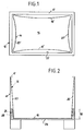
- FIG. 1
- a plan view of a lattice box during the insertion of a container,
- FIG. 2nd
- 2 shows a schematic sectional view through a container inserted into a mesh box,
- FIG. 3rd
- 2 shows a schematic sectional view through a modified embodiment of a container while it is being inserted into the mesh box,
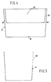
- FIG. 4th
- a side view of a container with one-sided half-high side wall and
- FIG. 5
- a cross section through the container of FIG. 4th
Die allgemein mit 10 bezeichnete Gitterbox hat zwei Seitenwände und zwei Stirnwände, die auf einem Boden senkrecht stehen. Am oberen Rand der Behälterwände befindet sich eine rahmenartige Einfassung 12, die aus einem Winkeleisenrahmen gebildet ist. Ein Kunststoffbehälter 14 weist einen ebenen Boden 16 sowie ebene Seitenwände 18 und ebenfalls ebene Stirnwände 20 auf. Die Einfassung 12 der Gitterbox 10 begrenzt eine rechteckförmige Zugangsöffnung 22 und der Boden 16 des Behälters 14 ist so dimensioniert, daß er gerade in die Zugangsöffnung 22 hineinpaßt. Die beiden Seitenwände 18 und die beiden Stirnwände 20 des Behälters 14 divergieren nach oben. Der Winkel, den jede Behälterwand mit der Vertikalen bildet, ist derselbe. Der Divergenzwinkel ist durch die Außendimensionen des Behälters 14 in Höhe seines Oberrandes bestimmt, denn in dieser Oberrandebene stimmen die Außendimensionen des Behälters 14 wenigstens angenähert mit den entsprechenden Innendimensionen der Gitterbox 10 überein. Um den Behälter 14 in die Gitterbox 10 einzusetzen, müssen seine Seiten- und Stirnwände 18, 20 in die Stellung 18' bzw. 20' einwärts gewölbt werden , wodurch sich der Behälter in Länge und Breite verkürzt. Nachdem der Boden 16 des Behälters 14 auf dem Boden der Gitterbox 10 gesetzt ist, läßt man die Seiten- und Stirnwände los, sodaß sie von selbst in ihre ebenen Stellungen zurückschnappen und sich an den entsprechenden Wänden der Gitterbox 10 anlegen. Die Herausnahme des Behälters 14 erfolgt entsprechend.The lattice box, generally designated 10, has two side walls and two end walls which are perpendicular to a floor. At the upper edge of the container walls there is a frame-
Der Behälter 14 besteht aus Polyethylen. Die Wandstärke ist gering. Gleichwohl bildet er die Möglichkeit Flüssigkeiten, pastöse Massen und Schüttgüter genausogut aufzunehmen, wie schwere Stückgüter.The
Für Schüttgüter mit besonders hoher Dichte wird zwischen den Wänden der Gitterbox 10 und den Wänden 18, 20 des Behälters 14 ein Stützrahmen 24 eingesetzt, der im Ausführungsbeispiel mit einem Boden 26 ausgebildet ist, sodaß Stützrahmen und Boden eine Wanne bilden. Im Ausführungsbeispiel ist der Stützrahmen 24 als Hohlkörper ausgebildet, der mit einer Polsterfüllung 28 aus Hartschaum oder dergl. versehen ist. Alternativ könnten die Außen- und Innenwände des Stützrahmens 24 auch durch horizontale Rippen versteift sein. Wesentlich ist, daß der Stützrahmen 24 ringsum eine Abstützung der Behälterwände 18,20 erlaubt und sich dabei vorzugsweise außen an den Wänden der Gitterbox 10 abstützt. Der Stützrahmen 24 bildet also einen Distanzring, der den Abstand zwischen Behälter 14 und Gitterbox 10 im unteren Teil der Kombination 10, 14 aufüllt. Dank dieses Stützrahmens 24 ist der Behälter 14 in der Gitterbox 10 unverschiebbar positioniert. Auch bei einer Schräglage der Kombination bleibt diese Position erhalten, was wegen der verformbaren Seitenwände des Behälters 14 möglicherweise nicht der Fall wäre. Außerdem erlaubt der Stützrahmen 24 die Beladung des dünnwandigen Behälters 14 mit Schütt- oder Fließgütern hoher Dichte. Die Behälterwandung ist im gefährdeten unteren Bereich von der Druckbeanspruchung entlastet, da diese vom Stützrahmen 24 aufgenommen wird, der bei richtiger Dimensionierung sich selbst wiederum an der Gitterbox 10 abstützt.For bulk goods with a particularly high density, a
Die Höhe 30 des Stützrahmens 24 wird so gewählt, daß dieser ohne Verformung unter entsprechender Verkantung durch die von der Einfassung 12 begrenzte Zugangsöffnung 22 der Gitterbox 10 paßt. Da sich der Stützrahmen 24 sowohl innenseitig als auch außenseitig an die Behälterwände 18, 20 bzw. die Gitterboxwände anschmiegen soll, verjüngt sich die Wandstärke des Stützrahmens 24 entsprechend der Konizität des Behälters 14 nach oben, wobei die Außenflächen des Stützrahmens 24 vertikal angeordnet sind, also rechtwinklig auf dem Boden 26 stehen.The
FIG. 3 veranschaulicht dieselbe Gitterbox 10 wie die Figuren 1 und 2, der Behälter 15 unterscheidet sich jedoch vom Behälter 14 dadurch, daß er hochflexibel und vorzugsweise ebenfalls elastisch verformbar ausgebildet ist und daß es sich um einen prismatischen Behälter handelt, bei dem die Behälterwände auf dem Boden wenigstens angenähert senkrecht stehen. Lediglich für das raumsparende Ineinanderschachteln kann eine gewisse Konizität wünschenswert sein. Die Außendimensionen des Bodens des Behälters 15 sind wenigstens angenähert gleich den entsprechenden Innendimensionen der Gitterbox 10 und da die Behälterwände des Behälters 15 im wesentlichen senkrecht stehen, ist der Außenquerschnitt des Behälters 15 in jeder beliebigen Höhe etwa gleich dem Innenquerschnitt der Gitterbox 10.FIG. 3 illustrates the
Um den Behälter 15 in die Gitterbox 10 einzusetzen, müssen nicht nur die Seitenwände sondern auch der Boden gewölbt werden, wie dies FIG. 3 veranschaulicht. Sobald der Behälter 15 vollständig in die Gitterbox 10 eingesetzt ist, werden die auf den Behälter ausgeübten Verformungskräfte weggenommen und aufgrund der Elastizität schnappen Boden und Seitenwände in ihre ursprüngliche ebene Ausgangsform zurück und legen sich dabei eng an den Boden und die Seitenwände der Gitterbox an.In order to insert the
Die Figuren 4 und 5 veranschaulichen einen Behälter 14, der sich von der vorbeschriebenen Ausführungsform dadurch unterscheidet, daß eine Seitenwand 18 im Mittelbereich nicht bis zum Oberrand des Behälters 14 reicht, sondern etwa auf halber Höhe endet, sodaß eine seitliche Zugangsöffnung 32 gebildet wird, die allerdings nicht über die ganze Breite der Längswand 18 reicht, vielmehr in geringen Abständen von den Stirnwänden 20 endet, sodaß Längswandstege 34 verbleiben, die die Zugangsöffnung 32 seitlich begrenzen. Diese Längswandstege 34 erhöhen die Steifigkeit des Behälters 14. Die Zugangsöffnung 32 ermöglicht es,an den Inhalt einer Gitterbox auch dann heranzukommen, wenn mehrere solcher Gitterboxen übereinandergestapelt sind, denn die Gitterboxen haben in der Längswand Klappen, nach deren Öffnung der Inhalt des Behälters durch die seitliche Zugangsöffnung 32 hindurch erreichbar ist.FIGS. 4 and 5 illustrate a
Es versteht sich, daß die seitliche Zugangsöffnung 32 auch bei dem prismatischen Behälter 15 gemäß FIG. 3 vorgesehen werden kann.It goes without saying that the lateral access opening 32 also in the
Claims (9)
Applications Claiming Priority (2)
| Application Number | Priority Date | Filing Date | Title |
|---|---|---|---|
| DE19914108387 DE4108387A1 (en) | 1991-03-15 | 1991-03-15 | LINING FOR PRISMATIC GRID BOXES |
| DE4108387 | 1991-03-15 |
Publications (2)
| Publication Number | Publication Date |
|---|---|
| EP0509220A2 true EP0509220A2 (en) | 1992-10-21 |
| EP0509220A3 EP0509220A3 (en) | 1993-02-10 |
Family
ID=6427345
Family Applications (1)
| Application Number | Title | Priority Date | Filing Date |
|---|---|---|---|
| EP19920103627 Withdrawn EP0509220A3 (en) | 1991-03-15 | 1992-03-03 | Lining for prismatic skeleton containers |
Country Status (2)
| Country | Link |
|---|---|
| EP (1) | EP0509220A3 (en) |
| DE (1) | DE4108387A1 (en) |
Cited By (2)
| Publication number | Priority date | Publication date | Assignee | Title |
|---|---|---|---|---|
| AU726038B2 (en) * | 1995-06-21 | 2000-10-26 | B A Lancaster Limited | Containers and bins |
| CN106945948A (en) * | 2017-04-28 | 2017-07-14 | 中国电建集团贵阳勘测设计研究院有限公司 | Anti-collision method and device for discharge bin of coarse crushing workshop |
Citations (5)
| Publication number | Priority date | Publication date | Assignee | Title |
|---|---|---|---|---|
| US2297097A (en) * | 1940-08-31 | 1942-09-29 | Wilson F Best | Receptacle |
| AT218949B (en) * | 1960-08-05 | 1961-12-27 | Ernst Robathin | Carrying basket |
| DE1173014B (en) * | 1961-08-16 | 1964-06-25 | Volkswagenwerk Ag | Stackable liquid insert container, especially for the transport of paint |
| AT247782B (en) * | 1963-12-14 | 1966-06-27 | Huels Chemische Werke Ag | Lattice box pallet |
| CH548330A (en) * | 1972-02-18 | 1974-04-30 | Thurnherr Albert | CONTAINER FOR WASTE BAG. |
Family Cites Families (6)
| Publication number | Priority date | Publication date | Assignee | Title |
|---|---|---|---|---|
| FR2472514A1 (en) * | 1979-12-31 | 1981-07-03 | Sotralentz Sa | CONTAINER ON PALLET WITH FOLDED MESH PROTECTION DEVICE |
| AU2020483A (en) * | 1982-10-14 | 1984-04-19 | Ian Claude Thomas Campbell | Bulk bag stacking |
| CA1302312C (en) * | 1985-10-25 | 1992-06-02 | Dietmar J. Neumann | Flexible container |
| DE3545855A1 (en) * | 1985-12-23 | 1987-07-02 | Jakobsson E Thomas | CONTAINER FOR WATER OR OTHER LIQUIDS |
| DE3724764C1 (en) * | 1987-07-25 | 1988-09-15 | Lorraine De Recuperation De Re | Appliance for transporting liquid metallurgical slag |
| DE8801027U1 (en) * | 1988-01-28 | 1988-03-17 | Edelhoff Polytechnik Gmbh & Co, 58640 Iserlohn | Collection container |
-
1991
- 1991-03-15 DE DE19914108387 patent/DE4108387A1/en not_active Withdrawn
-
1992
- 1992-03-03 EP EP19920103627 patent/EP0509220A3/en not_active Withdrawn
Patent Citations (5)
| Publication number | Priority date | Publication date | Assignee | Title |
|---|---|---|---|---|
| US2297097A (en) * | 1940-08-31 | 1942-09-29 | Wilson F Best | Receptacle |
| AT218949B (en) * | 1960-08-05 | 1961-12-27 | Ernst Robathin | Carrying basket |
| DE1173014B (en) * | 1961-08-16 | 1964-06-25 | Volkswagenwerk Ag | Stackable liquid insert container, especially for the transport of paint |
| AT247782B (en) * | 1963-12-14 | 1966-06-27 | Huels Chemische Werke Ag | Lattice box pallet |
| CH548330A (en) * | 1972-02-18 | 1974-04-30 | Thurnherr Albert | CONTAINER FOR WASTE BAG. |
Cited By (2)
| Publication number | Priority date | Publication date | Assignee | Title |
|---|---|---|---|---|
| AU726038B2 (en) * | 1995-06-21 | 2000-10-26 | B A Lancaster Limited | Containers and bins |
| CN106945948A (en) * | 2017-04-28 | 2017-07-14 | 中国电建集团贵阳勘测设计研究院有限公司 | Anti-collision method and device for discharge bin of coarse crushing workshop |
Also Published As
| Publication number | Publication date |
|---|---|
| DE4108387A1 (en) | 1992-09-17 |
| EP0509220A3 (en) | 1993-02-10 |
Similar Documents
| Publication | Publication Date | Title |
|---|---|---|
| DE3819911C2 (en) | ||
| DE4117159C2 (en) | Transport and / or storage containers | |
| DE3101975A1 (en) | PACKAGING FOR A VARIETY OF EXHIBITION PACKS | |
| DE2209967A1 (en) | Box for packing eggs, fruits or other items | |
| DE69308661T2 (en) | Stackable-nestable packaging box with skeleton-type sides | |
| DE8209245U1 (en) | Collapsible container | |
| DE69500528T2 (en) | CONTAINER | |
| DE2852932A1 (en) | INSULATING CONTAINER | |
| DE19641686C2 (en) | Stackable containers, in particular storage and transport containers and container system | |
| DE69103990T2 (en) | Construction of containers. | |
| DE2729737B2 (en) | Tightly closable, divisible container | |
| EP0509220A2 (en) | Prismatic skeleton container having a lining | |
| EP0440844B1 (en) | Carrying crates with means to detachably connect carrying crates | |
| DE4103333A1 (en) | Rectangular container for transporting fish, meat or fruit - has bottom with drainage ducts and holes, longitudinal and transverse sides, and reinforced top rim | |
| DE1960113C3 (en) | Plastic box | |
| DE4317300C2 (en) | Box-shaped container made of plastic | |
| DE69508460T2 (en) | Stackable and stackable box with vertical columns | |
| DE102019132975A1 (en) | Attachment ring and transport container with a attachment ring | |
| DE202018104281U1 (en) | Container | |
| DE68902471T2 (en) | FOLDING BOX AND CUTTING THEREFOR. | |
| DE3319802A1 (en) | HORDE TO RECORD ITEMS | |
| DE202018102107U1 (en) | Stacking container and transport system for such containers | |
| DE202013100968U1 (en) | Pallet | |
| DE6908320U (en) | BOTTLE CREST | |
| DE202020000925U1 (en) | Reusable load carrier with reduced volume and textile covers for removal openings |
Legal Events
| Date | Code | Title | Description |
|---|---|---|---|
| PUAI | Public reference made under article 153(3) epc to a published international application that has entered the european phase |
Free format text: ORIGINAL CODE: 0009012 |
|
| AK | Designated contracting states |
Kind code of ref document: A2 Designated state(s): AT BE CH DE DK ES FR GB GR IT LI LU NL PT SE |
|
| PUAL | Search report despatched |
Free format text: ORIGINAL CODE: 0009013 |
|
| AK | Designated contracting states |
Kind code of ref document: A3 Designated state(s): AT BE CH DE DK ES FR GB GR IT LI LU NL PT SE |
|
| 17P | Request for examination filed |
Effective date: 19930426 |
|
| 17Q | First examination report despatched |
Effective date: 19940328 |
|
| STAA | Information on the status of an ep patent application or granted ep patent |
Free format text: STATUS: THE APPLICATION IS DEEMED TO BE WITHDRAWN |
|
| 18D | Application deemed to be withdrawn |
Effective date: 19940730 |