EP0508892A2 - Belichtungssystem für einen Farbvideodrucker - Google Patents
Belichtungssystem für einen Farbvideodrucker Download PDFInfo
- Publication number
- EP0508892A2 EP0508892A2 EP92400984A EP92400984A EP0508892A2 EP 0508892 A2 EP0508892 A2 EP 0508892A2 EP 92400984 A EP92400984 A EP 92400984A EP 92400984 A EP92400984 A EP 92400984A EP 0508892 A2 EP0508892 A2 EP 0508892A2
- Authority
- EP
- European Patent Office
- Prior art keywords
- cycolor
- film
- cycolor film
- exposing
- color video
- Prior art date
- Legal status (The legal status is an assumption and is not a legal conclusion. Google has not performed a legal analysis and makes no representation as to the accuracy of the status listed.)
- Withdrawn
Links
Images


Classifications
-
- B—PERFORMING OPERATIONS; TRANSPORTING
- B41—PRINTING; LINING MACHINES; TYPEWRITERS; STAMPS
- B41J—TYPEWRITERS; SELECTIVE PRINTING MECHANISMS, i.e. MECHANISMS PRINTING OTHERWISE THAN FROM A FORME; CORRECTION OF TYPOGRAPHICAL ERRORS
- B41J2/00—Typewriters or selective printing mechanisms characterised by the printing or marking process for which they are designed
- B41J2/435—Typewriters or selective printing mechanisms characterised by the printing or marking process for which they are designed characterised by selective application of radiation to a printing material or impression-transfer material
-
- G—PHYSICS
- G03—PHOTOGRAPHY; CINEMATOGRAPHY; ANALOGOUS TECHNIQUES USING WAVES OTHER THAN OPTICAL WAVES; ELECTROGRAPHY; HOLOGRAPHY
- G03B—APPARATUS OR ARRANGEMENTS FOR TAKING PHOTOGRAPHS OR FOR PROJECTING OR VIEWING THEM; APPARATUS OR ARRANGEMENTS EMPLOYING ANALOGOUS TECHNIQUES USING WAVES OTHER THAN OPTICAL WAVES; ACCESSORIES THEREFOR
- G03B15/00—Special procedures for taking photographs; Apparatus therefor
- G03B15/003—Apparatus for photographing CRT-screens
-
- H—ELECTRICITY
- H04—ELECTRIC COMMUNICATION TECHNIQUE
- H04N—PICTORIAL COMMUNICATION, e.g. TELEVISION
- H04N1/00—Scanning, transmission or reproduction of documents or the like, e.g. facsimile transmission; Details thereof
- H04N1/46—Colour picture communication systems
- H04N1/50—Picture reproducers
Definitions
- the present invention relates to an exposure system for use in a color video printer, and more particularly to an exposure system for use in a cycolor type color video printer which is capable of reducing the manufacturing cost of a printer by use of light emitting diodes(LED) as an exposing light source.
- LED light emitting diodes
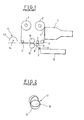
- the conventional color video printer comprises a supply roller 2 for supplying a cycolor film 1, a take-up roller 3 for winding up the cycolor film 1, a plurality of guide rollers 4 and 4' for guiding the cycolor film 1, a fiber optics cathode ray tube (FOCRT) 5 for exposing the cycolor film 1 which is drawn out of the supply roller 2, a capstan roller 6 and a pinch roller 7 for transferring the cycolor film 1, feeding rollers 9 and 9' for transferring receiver papers 8 to the running path of the cycolor film 1, upper and lower developing rollers 10 and 10' for applying a predetermined pressure to the cycolor film 1 which has been exposed by the FOCRT 5 and to the receiver paper 8 so that picture images of the cycolor film 1 can be developed on the receiver paper 8, and a
- Such a conventional color video printer operates as follows.
- the cycolor film 1 which is fed from the supply roller 2 is transferred at a predetermined speed by the rotation of the capstan roller 6 and guided by the guide rollers 4 and 4' and then wound-up on the take-up roller 3. At this moment, an exposing procedure is executed to the cycolor film 1 at an outlet side of the supply roller 2 by the FOCRT 5 which is spaced apart from the cycolor film 1.
- the receiver paper 8 is transferred to the running path of the cycolor film 1 so that the receiver paper 8 passes through the upper and lower developing rollers 10 and 10' together with the cycolor film 1, thereby transcribing the picture images of the cycolor film 1 to the receiver paper 8. That is, a developing procedure is carried out.
- cyliths particles On the surface of the cycolor film 1, several millions of cyliths particles of 2 /1 .m to to 12 /1 .m in diameter are doped in which leuco dye 16 is filled in a light sensitive micro capsules 15.
- leuco dye 16 As for the cyliths particles, there are three types, i.e., a cyan leuco dye, a magenta leuco dye, and a yellow leuco dye.
- the cyan leuco dye is subject to hardening when it is exposed to a red light.
- the magenta leuco dye is subject to hardening when it is exposed to a green light.
- the yellow leuco dye is subject to hardening when it is exposed to a blue light.
- an exposing light source for the cycolor film 1 since the light is dependent upon the wavelength, it is ideal that an exposing light source for the cycolor film 1 has a wavelength similar to that of cyliths particle.
- the picture images of the cycolor film 1 which have been exposed in the exposing procedure are transcribed on the receiver paper 8 by the upper and lower developing rollers 10 and 10' in the developing procedure. Thereafter, the receiver paper 8 is transferred to a heat-fixing unit 11 so that the picture images are heat-fixed on the receiver paper 8 by the heat from the heater 14.
- an object of the present invention to provide an exposure system for use in a color video printer which uses light emitting diodes which have a light distribution characteristic similar to that of cyliths particles as a light source, thereby reducing the size of color video printer and the manufacturing cost.
- the color video printer comprises film supplying and take-up units for supplying and taking up a cycolor film, an exposing unit for exposing the cycolor film, a paper supplying unit for supplying receiver papers, a developing unit for developing a picture image of the cycolor film on the receiver paper, and a heat-fixing unit for fixing the picture image which has been developed on the receiver paper.
- the present invention relates, especially, to an exposing unit comprising light sources each for generating red, green and blue lights, respectively, focusing members for focusing the light from the light sources to a cycolor film, and a transferring memeber for transferring the exposed film at a predetermined speed.
- the exposing unit of the present invention comprises light emitting diode (LED) arrays each for generating red, green and blue lights, respectively, a drive circuit for applying drive signals to the LED arrays, a base roller disposed at the running path of the cycolor film for transferring the cycolor film and functioning as a base surface in the exposing procedure, and micro lens arrays disposed between the LED arrays and the base roller for focusing the light from the LED arrays to the cycolor film.
- LED light emitting diode
- the exposure system for use in a color video printer as shown in Figs. 6 to 8 comprises a supplying and take-up unit for supplying and taking up a cycolor film 21, an exposing unit for exposing the cycolor film 21, a paper feeding unit for feeding a receiver paper 22, a developing unit for applying a predetermined pressure to the cycolor film 21 which has been exposed by the exposing unit and the receiver paper 22 and developing a picture image of the cycolor film 21 on the receiver paper 22, and a heat-fixing unit for fixing the picture image which has been developed on the receiver paper 22.
- the supplying and take-up unit includes a supply roller 23 for supplying the cycolor film 21, a take-up roller 24 for taking up the developed cycolor film 21, and a capstan roller 26 and a pinch roller 27 for transferring the cycolor film 21.
- the exposing unit includes LED arrays 28, 28' and 28" each for generating red, green and blue light, respectively, a drive circuit 29 for applying a drive signal to the LED arrays 28, 28' and 28", a base roller 30 disposed at the running path of the cycolor film 21 for functioning as a base surface of the cycolor film 21 in the exposing procedure, and micro lens arrays 31, 31' and 31" disposed between the LED arrays 28, 28' and 28" and the base roller 30 for focusing the light from the LED arrays 28, 28' and 28" to the cycolor film 21.
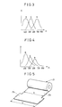
- the light emitting diode which is utilized as a light source in the present invention has the light-distribution characteristic as shown in Fig. 3.
- the light-distribution characteristic of the light emitting diode is similar to that of the cyliths particle as shown in Fig. 4. Thus, it can be used as an ideal light source of the exposure system by adjusting the wavelengths of red, green and blue lights through a compensating method such as a gamma- compensation.
- driven gears 32 and 33 are coaxially mounted at the base roller 30 and the pinch roller 27 and the driven gear 32 of the base roller 30 is meshed with a drive gear 35 of a drive motor 34. Between the drive gear 35 and the driven gear 32 of the pinch roller 27, an idle gear 36 is engaged therewith so that the base roller 30 and the pinch roller 27 rotate in same direction by the driving force of the drive motor 34. In the above arrangements, it is preferrable to rotate the pinch roller 27 slightly faster than the base roller 30 so that the cycolor film 21 receives a predetermined tension force during its running.
- support plates 37 are fixed, respectively.
- Each of the support plates 37 is provided at both ends thereof with guide slots 37a and 37b through which guide shafts 40 and 41 of upper and lower guide rollers 38 and 39 are rotatably inserted.
- the upper and lower guide rollers 38 and 39 are in contact with the base roller 30.
- the guide shafts 40 and 41 are biased toward the shaft 30a of the base roller 30 by means of coil springs 42 and 43, respectively, one end of which is fixed to one support plate 37 and the other end of which is fixed to the guide shaft 40 or 41.
- a pair of arcuate sheet guiders 44 are provided with a predetermined gap so that the cycolor film 21 which has passed through the upper guide rollers 38 may be guided to the lower guide rollers 39.
- the paper feeding unit includes a paper cassette 45 for containing receiver papers 22 therein, and feed rollers 46 and 46' for guiding the receiver papers 22 from the paper cassette 45 to the running path of the cycolor film 21.
- the developing unit includes an upper and a lower developing rollers 47 and 47' for applying a predetermined pressure to the cycolor film 21 which has been exposed and the receiver paper 22 and developing a picture image of the cycolor film 21 on the receiver paper 22.
- the heat-fixing unit includes a heater 48 for applying a heat to the receiver paper 22, and a reflective mirror 49 for reflecting the heat from the heater 48 toward the receiver paper 22.
- the cycolor film 21 which is utilized in the exposure system of the present invention is provided at the front edge thereof with an initial guide portion 21 a whose width (W) is larger than the width (b) of the film portion 21 b to enable an initial setting of the film to be made easier.
- the cycolor-type color video printer of the present invention operates as follows :
- the initial guide portion 21 a of the cycolor film since the circumferential edge portions of the initial guide portion 21 a of the cycolor film is engaged between the base roller 30 and the upper guide rollers 38, the initial guide portion 21 a moves upon the guidance of the upper guide rollers 38 and then engaged between the base roller 30 and the lower guide rollers 39 upon the guidance of the sheet guiders 44 provided below the upper guide rollers 38.
- the driving force of the drive motor 34 is transmitted to the idle gear 36 so that the pinch roller 27 is rotated in the same direction as the base roller 30.
- the image information is applied to the LED arrays 28, 28' and 23" as R.G.B. image signals by the drive circuit 29. Then, the LED arrays 28, 28' and 28" generate red, green and blue lights containing the image signals, respectively, and the lights from the LED arrays 28, 28' and 28" are focused by the micro lens arrays 31, 31' and 31" and then irradiated to the film portion 21 b of the cycolor film 21 which is wound around the base roller 30, so that the image information is exposed to the cycolor film 21.
- the receiver paper 22 is also transferred to the running path by the rotation of the feeding rollers 46 and 46'. Thereafter, the cycolor film 21 and the receiver paper 22 pass together through the developing rollers 47 and 47' which are in contact with each other at a predetermined pressure so that the picture image of the cycolor film 21 is transcribed to the receiver paper 22.
- the cycolor film 21 is transferred to and wound aroung the take-up roller 24 and the receiver paper 22 is transferred to the heat-fixing unit so that the transcribed picture image is heat-fixed to the receiver paper 22 by the heat from the heater 48.
- the present invention provides the effect that it is possible to provide an exposure system for use in a color video printer which is simple in structure and inexpensive in mancfacturing cost by use of light emitting diodes as a light source instead of the conventional fiber optics cathode ray tube.
Landscapes
- Physics & Mathematics (AREA)
- General Physics & Mathematics (AREA)
- Engineering & Computer Science (AREA)
- Multimedia (AREA)
- Signal Processing (AREA)
- Printers Or Recording Devices Using Electromagnetic And Radiation Means (AREA)
- Projection-Type Copiers In General (AREA)
- Printers Characterized By Their Purpose (AREA)
- Dot-Matrix Printers And Others (AREA)
Applications Claiming Priority (2)
| Application Number | Priority Date | Filing Date | Title |
|---|---|---|---|
| KR1019910005593A KR920019538A (ko) | 1991-04-08 | 1991-04-08 | 싸이칼라 방식 칼라비디오 프린터의 노광장치 |
| KR559391 | 1991-04-08 |
Publications (2)
| Publication Number | Publication Date |
|---|---|
| EP0508892A2 true EP0508892A2 (de) | 1992-10-14 |
| EP0508892A3 EP0508892A3 (en) | 1993-04-28 |
Family
ID=19313022
Family Applications (1)
| Application Number | Title | Priority Date | Filing Date |
|---|---|---|---|
| EP19920400984 Withdrawn EP0508892A3 (en) | 1991-04-08 | 1992-04-08 | Exposure system for color video printer |
Country Status (3)
| Country | Link |
|---|---|
| EP (1) | EP0508892A3 (de) |
| JP (1) | JPH05211666A (de) |
| KR (1) | KR920019538A (de) |
Families Citing this family (3)
| Publication number | Priority date | Publication date | Assignee | Title |
|---|---|---|---|---|
| EA000971B1 (ru) | 1996-07-09 | 2000-08-28 | Сайколор Систем Инк. | Устройство экспонирования, способ экспонирования и печатающее устройство |
| KR19990044364A (ko) | 1996-07-09 | 1999-06-25 | 오오시마 야스히로 | 노광용 헤드 및 인쇄장치 |
| TWI366260B (en) | 2007-12-31 | 2012-06-11 | Universal Scient Ind Shanghai | Multi-wavelength light-emitting module with high density electrical connection |
Family Cites Families (3)
| Publication number | Priority date | Publication date | Assignee | Title |
|---|---|---|---|---|
| US4716285A (en) * | 1984-08-23 | 1987-12-29 | Fuji Photo Film Co., Ltd. | Light amount correction method and apparatus for image output system |
| US4918536A (en) * | 1986-03-04 | 1990-04-17 | Brother Kogyo Kabushiki Kaisha | Facsimile recording system using photosensitive microcapsule recording medium |
| US5003383A (en) * | 1987-02-18 | 1991-03-26 | Sharp Kabushiki Kaisha | Color image copier operable in analog and digital modes |
-
1991
- 1991-04-08 KR KR1019910005593A patent/KR920019538A/ko not_active Ceased
-
1992
- 1992-04-08 JP JP8721692A patent/JPH05211666A/ja active Pending
- 1992-04-08 EP EP19920400984 patent/EP0508892A3/en not_active Withdrawn
Also Published As
| Publication number | Publication date |
|---|---|
| JPH05211666A (ja) | 1993-08-20 |
| KR920019538A (ko) | 1992-11-19 |
| EP0508892A3 (en) | 1993-04-28 |
Similar Documents
| Publication | Publication Date | Title |
|---|---|---|
| US6278472B1 (en) | Thermal printer, thermal printing method and conveyor for recording material | |
| US4875074A (en) | Image recording apparatus | |
| US5743663A (en) | Record medium feeding in a color thermal printer | |
| US5216438A (en) | Direct color thermal printing method for optically and thermally recording a full-color image on a thermosensitive recording medium | |
| US6831732B2 (en) | Printer | |
| US5276464A (en) | Method and apparatus for loading and unloading superposed sheets on a vacuum drum | |
| US5428371A (en) | Laser thermal printer using roll material supply | |
| KR19990022069A (ko) | 드라이브 베이용 프린터 | |
| US4884082A (en) | Color image recording apparatus | |
| US5260714A (en) | Method of removing air from between superposed sheets | |
| US5072245A (en) | Image recording apparatus employing optical and heat energy to record image | |
| US5257038A (en) | Focusing laser diode mount on a write head | |
| EP0508892A2 (de) | Belichtungssystem für einen Farbvideodrucker | |
| US5280307A (en) | Selectively wound material for a laser thermal printer | |
| JP2883499B2 (ja) | 素材供給カルーゼル(回転ラック) | |
| JPS63303774A (ja) | プリンタ− | |
| GB2203255A (en) | Colour picture image recording apparatus | |
| US5264867A (en) | Method and apparatus for selectively sorting image-bearing sheets from scrap sheets | |
| US5034756A (en) | Light irradiation device having filter unit | |
| US4893010A (en) | Image recording apparatus | |
| EP0530634A2 (de) | Bildaufzeichnungstrommel | |
| US6670977B2 (en) | Image-recording method and image-recording system | |
| US5142321A (en) | Image recording apparatus built up with versatile unit and optional exposure unit | |
| US5079587A (en) | Image recording apparatus having device for adjusting position of mask members | |
| JP3406996B2 (ja) | 画像形成装置 |
Legal Events
| Date | Code | Title | Description |
|---|---|---|---|
| PUAI | Public reference made under article 153(3) epc to a published international application that has entered the european phase |
Free format text: ORIGINAL CODE: 0009012 |
|
| AK | Designated contracting states |
Kind code of ref document: A2 Designated state(s): DE FR GB NL |
|
| PUAL | Search report despatched |
Free format text: ORIGINAL CODE: 0009013 |
|
| AK | Designated contracting states |
Kind code of ref document: A3 Designated state(s): DE FR GB NL |
|
| 17P | Request for examination filed |
Effective date: 19930810 |
|
| STAA | Information on the status of an ep patent application or granted ep patent |
Free format text: STATUS: THE APPLICATION IS DEEMED TO BE WITHDRAWN |
|
| 18D | Application deemed to be withdrawn |
Effective date: 19941101 |