EP0508281B1 - Arc welding machine - Google Patents
Arc welding machine Download PDFInfo
- Publication number
- EP0508281B1 EP0508281B1 EP92105544A EP92105544A EP0508281B1 EP 0508281 B1 EP0508281 B1 EP 0508281B1 EP 92105544 A EP92105544 A EP 92105544A EP 92105544 A EP92105544 A EP 92105544A EP 0508281 B1 EP0508281 B1 EP 0508281B1
- Authority
- EP
- European Patent Office
- Prior art keywords
- output
- arc
- signal
- short
- current
- Prior art date
- Legal status (The legal status is an assumption and is not a legal conclusion. Google has not performed a legal analysis and makes no representation as to the accuracy of the status listed.)
- Expired - Lifetime
Links
Images






Classifications
-
- B—PERFORMING OPERATIONS; TRANSPORTING
- B23—MACHINE TOOLS; METAL-WORKING NOT OTHERWISE PROVIDED FOR
- B23K—SOLDERING OR UNSOLDERING; WELDING; CLADDING OR PLATING BY SOLDERING OR WELDING; CUTTING BY APPLYING HEAT LOCALLY, e.g. FLAME CUTTING; WORKING BY LASER BEAM
- B23K9/00—Arc welding or cutting
- B23K9/095—Monitoring or automatic control of welding parameters
- B23K9/0956—Monitoring or automatic control of welding parameters using sensing means, e.g. optical
Definitions
- This invention relates to a power supply unit used for the arc welding work.
- Conventional arc welding machines are controlled for the welding output power through the selection of an output value in a fixed power range in accordance with the predetermined rule of operation of a differential amplifier or the like which has a feedback of the state of arc.
- the welding output power is also controlled through the detection of a transition from the state of arcing to the state of short-circuiting and vice versa, and the switching of the output waveform according to the result of detection.
- the CO2 welding work will be explained in detail.
- the butt length is normally set from 10 to 20 mm.
- the tip of the welding torch cannot access to the welding position in some cases. In these cases, it is inevitable to carry out the welding work in a state of butt length as long as 50 mm, and the operation may encounter the difficulty of maintaining a constant butt length depending on the degree of expertness of the welding worker.
- the arc becomes unstable, which causes the deficiency of beads, resulting in a defective junction in that portion, or causes an uneven bead width or a too small average bead width, or causes a insuffient melting.
- the welding work with a longer butt length is carried out with its welding voltage adjusted higher than the usual condition.
- the butt length is short, while the welding output voltage is adjusted higher, such a trouble as melt-sticking of the wire to the electrode can emerge, and on this account it is necessary to re-adjust the output voltage each time the butt length varies.
- the foregoing welding power control based on the selection of an output value in a fixed power range in accordance with the predetermined rule of operation in response to the fed-back arc state, in which the selected output signal is one-to-one relation with the feedback signal, does not necessarily select the optimal output signal for stabilizing the immediate state of the arc, and this is a cause of instability of arcing.
- the control loop gain is set too small, the power output cannot respond immediately to a change in the state of arc, or if the loop gain is set too large, the output power overshoots, making the arc more unstable.
- the welding power control based on the switching of the output waveform by detecting the transition between the state of arcing and the state of short-circuiting under the foregoing feedback control is subjected to a delay of waveform switching, resulting in an improper output waveform for maintaining the optimal arc, which causes the disturbance of the output power. Since the initial phase of short-circuiting cannot be predicted, the emergence of a small-scale short-circuiting cannot be brought to a positive short-circuit state, and this causes the emergence of sputtering and uneven transition to the short-circuit state due to a varying period of transition, resulting in a poor appearance of beads.
- EP-0 300 367 A2 discloses and arc welding machine comprising means for automatically controlling the welding current, the feeding rate of the welding wire and the welding voltage on the basis of the respective target values determined by calculation. The calculation is performed arithmetically, i.e. on the basis of respective equations.
- fuzzy logic may be used in various technical fields, particularly in case that a lot of control values and measuring values are to be considered.
- the present invention is intended to overcome the foregoing prior art deficiencies, and its prime object is to provide an arc welding machine which produces the optimal output power by using multiple feedback signals through the inference based on the fuzzy theory.
- Another object of this invention is to provide an arc welding machine which produces the optimal output power through the measurement of the period of transition between the state of arcing and the state of short-circuiting based on the feedback signals and the prediction of the next state transition through the inference based on the fuzzy theory.
- Still another object of this invention is to provide an arc welding machine which calculates the butt length automatically during the welding operation and implements the power adjustment automatically based on the calculation result, thereby enhancing the efficiency of welding work and the quality of welding.
- the power supply unit for the arc welding work based on this invention comprises an output control means which produces an arc output in accordance with the output control signal, an output detection means which measures the state of arc output and produces feedback signals indicative of the arc state, and a fuzzy inference control means which introduces the feedback signals, produces a welding current waveform and welding voltage waveform required to produce the optimal arc state based on the fuzzy theory, and delivers the resulting waveforms to the output control means as the output control signal.
- the output detection means includes a signal conversion means which introduces the output arc voltage signal indicative of the arc voltage and the output arc current signal indicative of the arc current and produces an output arc voltage value signal and output arc current value signal, and a short-circuit event count means which introduces the output arc voltage signal, counts the number of events of contact between the welding wire, which is a consumable electrode, and the object of welding in a certain time period, and produces a short-circuit event count signal.
- the fuzzy inference control means includes a base power setting means which reads out a base output current waveform and a base output voltage waveform selectively from a data bank memory and delivers the waveforms as base output signals, and a fuzzy inference means which introduces the base output signals, output arc voltage value signal, output arc current value signal and short-circuit event count signal, implements the inference in accordance with the predetermined rules based on the fuzzy theory, and produces an output control signal which achieves the welding output current waveform and voltage waveform needed for the achievement of the optimal arc state.
- the output detection means includes a current detection means which measures the output current and produces a current value signal, a voltage detection means which measures the output voltage and produces a voltage value signal, and a short-circuiting/arcing period measuring means which introduces the voltage value signal to measure the time length since the beginning of previous short-circuiting until arc generation and the time length since arc generation until short-circuiting and produces a short-circuit/arc period signal.
- the fuzzy inference control means includes a fuzzy inference means which introduces the current value signal, voltage value signal and short-circuit/arc period signal, implements the fuzzy inference based on the predetermined rule thereby to predict the time length since the transition from the previous arcing to short-circuiting until the transition from the next short-circuiting to arcing, or the time length since the transition from the previous short-circuiting to arcing until the transition from the next arcing to short-circuiting, and produces an inference signal, and a waveform control means which introduces the inference signal and produces signals of output waveforms for achieving the optimal state of arc.
- the output detection means includes a current detection means which detects the welding current, a current value calculation means which introduces the output of the current detection means and calculates the mean value and effective value of the output current, and a wire feed rate detection means which detects the feed speed of wire which is a consumable electrode.
- the fuzzy inference control means includes a butt length calculation means which calculates the distance between the welding object and the electrode based on the calculation result provided by the current value calculation means and the detection result provided by the feed rate detection means, a fuzzy inference means which introduces the calculation result provided by the butt length calculation means as an input variable and evaluates the output setting value in accordance with the predetermined rule based on the fuzzy inference, and an output setting means which reads out the optimal output value from the database memory in response to the output setting value and sets the welding output.
- the welding machine operates through the inference based on the fuzzy theory in response to the reference signals and the feedback signals indicative of the state of arc, whereby the output waveform can be controlled to achieve the optimal state of arc.
- the welding machine operates through the inference based on the fuzzy theory in response to the period of transition between short-circuiting and arcing evaluated from the feedback signals as well as to the measured current value and voltage value thereby to predict the next transition between short-circuiting and arcing, whereby the output waveform can be controlled to achieve the optimal state of arc.
- the welding machine is capable of calculating the butt length during the welding operation from the mean value and effective value of output current and the wire feed rate thereby to adjust the output condition promptly and automatically based on the calculation result, whereby the efficiency of welding work and the quality of welding can be improved.
- reference numeral 1 denotes a fuzzy inference control circuit
- 2 is an output control circuit
- 3 is an output detection circuit.
- Indicated by FBS is a feedback signal indicative of the state of arc produced by the output detection circuit 3 and sent to the fuzzy inference control circuit 1
- CS is an output control signal produced by the fuzzy inference control circuit 1 and sent to the output control circuit 2.
- the output detection circuit 3 measures the present state of arc which is being maneuvered by the output control circuit 2 that is the actuator of the welding machine, and produces the arc-state feedback signal FBS.
- the fuzzy inference control circuit 1 receives the arc-state feedback signal FBS, implements the fuzzy inference for producing the output waveform for achieving the optimal state of arc based on the preset membership function, and delivers the resulting output control signal CS.
- the output control circuit 2 performs the arc control in accordance with the output control signal CS.
- the fuzzy inference control circuit 1 includes a fuzzy inference circuit 11 and a base output setting circuit 12, and the output detection circuit 3 includes a short-circuit event count circuit 31 and a signal conversion circuit 32.
- the signal conversion circuit 32 introduces the arc current value and arc voltage value, which reflect the present operation of the welding machine, as an output arc current signal Ao and output arc voltage signal Vo, and delivers an output arc current signal AS and output arc voltage signal VS.
- the short-circuit event count circuit 31 monitors the output arc voltage signal Vo and determines the occurrence of short-circuiting of the wire on detecting a falling voltage below a certain level, and counts the number of events of short-circuiting in a certain time period to produce a short-circuit event count signal SS.
- the base output setting circuit 12 reads out selectively from the data bank memory a base welding output current waveform and voltage waveform for the welding output current and voltage command values given from the outside, and delivers a resulting base output signal KS.
- the fuzzy inference circuit 11 introduces the base output signal KS, the short-circuit event count signal SS, the output arc current value signal AS and output arc voltage value signal VS, renders weights to the signals SS, AS and VS in the form of membership function, implements the fuzzy inference based on the predetermined rule, adjusts finely the base output signal KS in accordance with the inference result, and delivers an output control signal CS for controlling the output values so as to achieve the optimal state of arc.
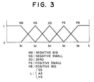
- Fig. 3 is a graph showing the membership function of the short-circuit event count signal SS, output arc current value signal AS and output arc voltage value signal VS, and the following are expressions of the membership function.
- ⁇ A (X) max (0, 1-
- Rules of fuzzy inference are established in advance based on the experience of skilled welding workers, and each rule takes the IF-THEN form of three inputs and one output as follows.
- the fuzzy inference circuit 11 and base output setting circuit 12 can readily be realized with a microprocessor or the like, and the short-circuit event count circuit 31 can readily be realized with a comparator, counter, etc. configured as integrated circuits.
- the fuzzy inference circuit 11 of this embodiment adopts the simplified fuzzy inference based on the lookup table for delivering the output of THEN clause of rule
- the circuit may employ the formal fuzzy inference in which both the IF clause and THEN clause are treated in the form of membership function.
- reference symbol 10 denotes a fuzzy inference circuit
- 20 is a waveform control circuit
- 30 is a short-circuiting/arcing period measuring circuit
- 40 is a voltage detection circuit
- 50 is a current detection circuit
- 60 is a drive control circuit
- 70 is an output drive element
- 80 is an input terminal
- 90 is a primary rectifier
- 100 is a capacitor
- 110 is a main transformer
- 120 is a secondary rectifier
- 130 is a reactor
- 140 is a current transformer
- 150a and 150b are output terminals
- 160 is a current contact chip
- 170 is a welding wire
- 180 is a welding object.
- the current detection circuit 50 measures the output arc current by using the current transformer 140, and produces a current value signal AS which consists of an instantaneous component and average component.
- the voltage detection means 40 measures the output arc voltage between the output terminals 150a and 150b, and produces a voltage value signal VS which consists of an instantaneous component and average component.
- the short-circuiting/arcing period measuring circuit 30 introduces the voltage value signal VS provided by the voltage detection circuit 40, determines the state of short-circuit or arcing between the welding wire 170 and welding object 180 based on the instantaneous component of the signal, measures the time length since the beginning of short-circuiting until arcing and the time length since arcing until the beginning of short-circuiting, and delivers a resulting short-circuit/arc period signal FS.
- the fuzzy inference circuit 10 introduces the current value signal AS, voltage value signal VS and short-circuit/arc period signal FS thereby to extract the instantaneous component and average component of the current value signal AS, the average component of the voltage value signal VS, the time length since the beginning of short-circuiting until arcing, and the time length since arcing until the beginning of short-circuiting as parameters of inference, infers the time length from the next beginning of short-circuiting to arcing or from arcing to short-circuiting based on the multiplexed fuzzy inference theory, and delivers the result of inference as an inference signal LS.
- the fuzzy inference circuit 10 can readily be realized with a microprocessor or the like.
- the waveform control circuit 20 produces an output waveform by combining output waveforms at the next short-circuiting and arcing read out of the internal data bank memory in response to she inference signal LS provided by the fuzzy inference circuit 10, and delivers a waveform signal WS.
- the drive control circuit 60 introduces the waveform signal WS, transforms it into a drive signal DS, and delivers the signal DS to the output drive element 70.
- Figs. 5A and 5B are a set of diagrams used to explain the operation of the fuzzy inference circuit 10
- Figs. 6A and 6B are a set of waveform diagrams showing the voltage value signal and current value signal.
- the fuzzy inference circuit 10 bases its operation on the multiplexed fuzzy inference theory, and evaluates the output of the membership function ⁇ (x) based on the max-min composed centroid method.
- the inference circuit has six inputs as shown in Figs. 5A and 5B, and it implements the inference in accordance with the predetermined rule to produce an output ts1 or ta1.
- the circuit introduces into the membership function ⁇ (x) the previous short-circuiting time TS0, the previous arcing time Ta0, the current value at the previous transition from arcing to short-circuiting Ib0, the current value at the previous transition from short-circuiting to arcing IP0, and the output average current value Ia and average voltage value Va of the present short-circuiting/arcing period, implements the inference in accordance with the predetermined rule, and produces a present inferenced short-circuiting time tS1, as shown in Fig. 5A.
- the circuit introduces into the membership function ⁇ (x) the previous arcing time Ta0, the present short-circuiting time TS1, the current value at the previous transition from short-circuiting to arcing IP0, the current value at the present transition from arcing to short-circuiting Ib1, and the output average current value Ia' and output average voltage value Va' of the previous short-circuiting/arcing period, implements the inference in accordance with the predetermined rule, and produces an inferenced arcing time ta1, as shown in Fig. 5B.
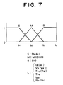
- Fig. 7 is a graph showing the membership function of the input variables Ia, Ia', Va, Va', TS0, TS1, Ta1, Ta0, IP0, Ib0, and Ib1 in the IF clause, and the following are expressions of the membership function.
- membership function of fuzzy variable S (X: input variable) membership function of fuzzy variables M ⁇ A (X) max (0, 1-
- the membership function for producing the output values tS1 and ta1 has three variables as in the previous embodiment.
- reference symbol 100 denotes a current detection circuit
- 200 is a current value calculation circuit
- 300 is a wire feed rate detection circuit
- 400 is a butt length calculation circuit
- 5100 is a fuzzy inference circuit
- 5200 is an output value setting circuit
- 5300 is a database memory
- 600 is an output drive control circuit
- 700 is an output drive element
- 800 is a main transformer
- 900 is a secondary rectifier
- 1000 is a shunt device
- 1100a and 1100b are output terminals
- 1200 is a welding object
- 1300 is an electrode
- 1400 is a wire which is a consumable electrode.
- the current detection circuit 100 detects the value of present welding current by means of the shunt device 1000 placed between the secondary rectifier 900 and output terminal 1100, and produces a current value signal.
- the current calculation circuit 200 receives the current value signal from the current detection circuit 100 and calculates the mean value and effective value of the output current based on a microcomputer or the like.
- the feed rate detection circuit 300 counts the number of revolutions of a roller which is in contact with the consumable electrode wire 1400 and coupled with a rotary encoder or tachogenerator thereby to evaluate the feed rate of the wire, and produces a feed rate signal.
- the butt length calculation circuit 400 introduces the mean value and effective value of the output current and the wire feed rate, and calculates the butt length.
- the fuzzy inference circuit 5100 introduces the butt length calculated by the butt length calculation circuit 400, assesses the butt length into five categories of "short”, “normal”, “slightly long”, “long” and “very long”, implements the weighting operation in accordance with the membership function, and produces a signal indicative of the adjustment value of the welding output from the result of inference.
- the output value setting circuit 5200 reads out an adjustment value from the database memory in response to the command signal from the fuzzy inference circuit 5100, and delivers the output adjustment value to the output drive control circuit 600.
- the feed rate detection circuit 300 counts the number of revolutions of a roller, which is in contact with the consumable electrode wire 1400 and coupled with an encoder or tachogenerator
- alternative arrangements for the detection of feed rate include the use of interference of laser rays reflected on the wire and the use of the number of revolutions of the wire feed motor.
- the arc welding machine of the type of consumable electrode calculates the butt length and adjusts the welding power automatically based on the calculation result.
- the optimal output waveform can be inferred from the immediate state of arc, which enables the achievement of stable and optimal arcing and facilitates arc welding for the workers.
- the machine enables the prediction of the next beginning of short-circuiting and arcing based on the immediate state of arc, which eliminates the delay of waveform control and ensures the transition to short-circuiting by eliminating small-scale short-circuiting through the control of short-circuit starting time, whereby the emergence of sputtering can be prevented, a smooth bead appearance can be realized based on uniform arcing, and allows the worker to have easily a stable and optimal arc.
- the machine frees the worker from the awkward re-adjustment of the output power in response to the variation of butt length, prevents the degradation of quality of welding due to improper output adjustment or suspension of welding for the output re-adjustment, ensures the stable welding result irrespective of the degree of extertness of workers.
Landscapes
- Engineering & Computer Science (AREA)
- Physics & Mathematics (AREA)
- Plasma & Fusion (AREA)
- Mechanical Engineering (AREA)
- Arc Welding Control (AREA)
- Feedback Control In General (AREA)
Description
- This invention relates to a power supply unit used for the arc welding work.
- Conventional arc welding machines are controlled for the welding output power through the selection of an output value in a fixed power range in accordance with the predetermined rule of operation of a differential amplifier or the like which has a feedback of the state of arc. The welding output power is also controlled through the detection of a transition from the state of arcing to the state of short-circuiting and vice versa, and the switching of the output waveform according to the result of detection.
- As a typical example of the consumable electrode arc welding work, the CO₂ welding work will be explained in detail. In this welding work, the butt length is normally set from 10 to 20 mm. However, in welding a structure of complex shape or a large structure which involve narrow deep sections, the tip of the welding torch cannot access to the welding position in some cases. In these cases, it is inevitable to carry out the welding work in a state of butt length as long as 50 mm, and the operation may encounter the difficulty of maintaining a constant butt length depending on the degree of expertness of the welding worker.
- In the state of a longer butt length, the arc becomes unstable, which causes the deficiency of beads, resulting in a defective junction in that portion, or causes an uneven bead width or a too small average bead width, or causes a insuffient melting.
- In order to prevent the above-mentioned adverse inference on the result of welding and the condition of operation, the welding work with a longer butt length is carried out with its welding voltage adjusted higher than the usual condition. However, if the butt length is short, while the welding output voltage is adjusted higher, such a trouble as melt-sticking of the wire to the electrode can emerge, and on this account it is necessary to re-adjust the output voltage each time the butt length varies.
- However, the foregoing welding power control based on the selection of an output value in a fixed power range in accordance with the predetermined rule of operation in response to the fed-back arc state, in which the selected output signal is one-to-one relation with the feedback signal, does not necessarily select the optimal output signal for stabilizing the immediate state of the arc, and this is a cause of instability of arcing. In addition, if the control loop gain is set too small, the power output cannot respond immediately to a change in the state of arc, or if the loop gain is set too large, the output power overshoots, making the arc more unstable.
- Moreover, the welding power control based on the switching of the output waveform by detecting the transition between the state of arcing and the state of short-circuiting under the foregoing feedback control is subjected to a delay of waveform switching, resulting in an improper output waveform for maintaining the optimal arc, which causes the disturbance of the output power. Since the initial phase of short-circuiting cannot be predicted, the emergence of a small-scale short-circuiting cannot be brought to a positive short-circuit state, and this causes the emergence of sputtering and uneven transition to the short-circuit state due to a varying period of transition, resulting in a poor appearance of beads.
- In the semi-automatic welding work, the operation needs to be halted for the output adjustment each time the butt length varies as mentioned above, which makes the welding work awkward and inefficient and also adversely affects the quality of welding. It is very difficult to measure from outside the butt length of welding which goes on currently or the butt length for the subsequent welding operation, and therefore the welding power must be adjusted on a try-and-error basis, which imposes increased problems on the efficiency of work and on the degradation of welding quality caused by improper adjustment.
- EP-0 300 367 A2 discloses and arc welding machine comprising means for automatically controlling the welding current, the feeding rate of the welding wire and the welding voltage on the basis of the respective target values determined by calculation. The calculation is performed arithmetically, i.e. on the basis of respective equations.
- What is to be taken from "c't Magazin für Computertechnik, March 1991, pages 188 - 206, C. von Altrock, "Über den Daumen gepeilt, fuzzy logic: Scharfe Theorie der unscharfen Mengen", is that the principle of fuzzy logic may be used in various technical fields, particularly in case that a lot of control values and measuring values are to be considered.
- The present invention is intended to overcome the foregoing prior art deficiencies, and its prime object is to provide an arc welding machine which produces the optimal output power by using multiple feedback signals through the inference based on the fuzzy theory.
- Another object of this invention is to provide an arc welding machine which produces the optimal output power through the measurement of the period of transition between the state of arcing and the state of short-circuiting based on the feedback signals and the prediction of the next state transition through the inference based on the fuzzy theory.
- Still another object of this invention is to provide an arc welding machine which calculates the butt length automatically during the welding operation and implements the power adjustment automatically based on the calculation result, thereby enhancing the efficiency of welding work and the quality of welding.
- The power supply unit for the arc welding work based on this invention comprises an output control means which produces an arc output in accordance with the output control signal, an output detection means which measures the state of arc output and produces feedback signals indicative of the arc state, and a fuzzy inference control means which introduces the feedback signals, produces a welding current waveform and welding voltage waveform required to produce the optimal arc state based on the fuzzy theory, and delivers the resulting waveforms to the output control means as the output control signal.
- More specifically, the output detection means includes a signal conversion means which introduces the output arc voltage signal indicative of the arc voltage and the output arc current signal indicative of the arc current and produces an output arc voltage value signal and output arc current value signal, and a short-circuit event count means which introduces the output arc voltage signal, counts the number of events of contact between the welding wire, which is a consumable electrode, and the object of welding in a certain time period, and produces a short-circuit event count signal. The fuzzy inference control means includes a base power setting means which reads out a base output current waveform and a base output voltage waveform selectively from a data bank memory and delivers the waveforms as base output signals, and a fuzzy inference means which introduces the base output signals, output arc voltage value signal, output arc current value signal and short-circuit event count signal, implements the inference in accordance with the predetermined rules based on the fuzzy theory, and produces an output control signal which achieves the welding output current waveform and voltage waveform needed for the achievement of the optimal arc state.
- The output detection means includes a current detection means which measures the output current and produces a current value signal, a voltage detection means which measures the output voltage and produces a voltage value signal, and a short-circuiting/arcing period measuring means which introduces the voltage value signal to measure the time length since the beginning of previous short-circuiting until arc generation and the time length since arc generation until short-circuiting and produces a short-circuit/arc period signal. The fuzzy inference control means includes a fuzzy inference means which introduces the current value signal, voltage value signal and short-circuit/arc period signal, implements the fuzzy inference based on the predetermined rule thereby to predict the time length since the transition from the previous arcing to short-circuiting until the transition from the next short-circuiting to arcing, or the time length since the transition from the previous short-circuiting to arcing until the transition from the next arcing to short-circuiting, and produces an inference signal, and a waveform control means which introduces the inference signal and produces signals of output waveforms for achieving the optimal state of arc.
- The output detection means includes a current detection means which detects the welding current, a current value calculation means which introduces the output of the current detection means and calculates the mean value and effective value of the output current, and a wire feed rate detection means which detects the feed speed of wire which is a consumable electrode. The fuzzy inference control means includes a butt length calculation means which calculates the distance between the welding object and the electrode based on the calculation result provided by the current value calculation means and the detection result provided by the feed rate detection means, a fuzzy inference means which introduces the calculation result provided by the butt length calculation means as an input variable and evaluates the output setting value in accordance with the predetermined rule based on the fuzzy inference, and an output setting means which reads out the optimal output value from the database memory in response to the output setting value and sets the welding output.
- According to this invention, the welding machine operates through the inference based on the fuzzy theory in response to the reference signals and the feedback signals indicative of the state of arc, whereby the output waveform can be controlled to achieve the optimal state of arc.
- According to this invention, the welding machine operates through the inference based on the fuzzy theory in response to the period of transition between short-circuiting and arcing evaluated from the feedback signals as well as to the measured current value and voltage value thereby to predict the next transition between short-circuiting and arcing, whereby the output waveform can be controlled to achieve the optimal state of arc.
- According to this invention, the welding machine is capable of calculating the butt length during the welding operation from the mean value and effective value of output current and the wire feed rate thereby to adjust the output condition promptly and automatically based on the calculation result, whereby the efficiency of welding work and the quality of welding can be improved.
-
- Fig. 1 is a block diagram showing the first embodiment of this invention;
- Fig. 2 is a block diagram showing the second embodiment of this invention;
- Fig. 3 is a diagram explaining the membership function of the second embodiment of this invention;
- Fig. 4 is a block diagram showing the third embodiment of this invention;
- Fig. 5A and 5B are a set of diagrams used to explain the operation of the fuzzy inference means of the third embodiment of this invention;
- Figs. 6A and 6B are a set of waveform diagrams showing the voltage signal and current signal of the third embodiment of this invention;
- Fig. 7 is a diagram explaining the membership function of the third embodiment of this invention;
- Fig. 8 is a block diagram showing the fourth embodiment of this invention; and
- Fig. 9 is a diagram explaining the membership function of the fourth emodiment of this invention.
- The first embodiment of this invention will be explained with reference to the drawings.
- In the block diagram of Fig. 1,
reference numeral 1 denotes a fuzzy inference control circuit, 2 is an output control circuit, and 3 is an output detection circuit. Indicated by FBS is a feedback signal indicative of the state of arc produced by theoutput detection circuit 3 and sent to the fuzzyinference control circuit 1, and CS is an output control signal produced by the fuzzyinference control circuit 1 and sent to the output control circuit 2. - The
output detection circuit 3 measures the present state of arc which is being maneuvered by the output control circuit 2 that is the actuator of the welding machine, and produces the arc-state feedback signal FBS. The fuzzyinference control circuit 1 receives the arc-state feedback signal FBS, implements the fuzzy inference for producing the output waveform for achieving the optimal state of arc based on the preset membership function, and delivers the resulting output control signal CS. The output control circuit 2 performs the arc control in accordance with the output control signal CS. - The second embodiment of this invention will be explained with reference to the drawings.
- In Fig. 2, the fuzzy
inference control circuit 1 includes a fuzzy inference circuit 11 and a baseoutput setting circuit 12, and theoutput detection circuit 3 includes a short-circuitevent count circuit 31 and asignal conversion circuit 32. - The
signal conversion circuit 32 introduces the arc current value and arc voltage value, which reflect the present operation of the welding machine, as an output arc current signal Ao and output arc voltage signal Vo, and delivers an output arc current signal AS and output arc voltage signal VS. - The short-circuit
event count circuit 31 monitors the output arc voltage signal Vo and determines the occurrence of short-circuiting of the wire on detecting a falling voltage below a certain level, and counts the number of events of short-circuiting in a certain time period to produce a short-circuit event count signal SS. - The base
output setting circuit 12 reads out selectively from the data bank memory a base welding output current waveform and voltage waveform for the welding output current and voltage command values given from the outside, and delivers a resulting base output signal KS. - The fuzzy inference circuit 11 introduces the base output signal KS, the short-circuit event count signal SS, the output arc current value signal AS and output arc voltage value signal VS, renders weights to the signals SS, AS and VS in the form of membership function, implements the fuzzy inference based on the predetermined rule, adjusts finely the base output signal KS in accordance with the inference result, and delivers an output control signal CS for controlling the output values so as to achieve the optimal state of arc.
- Fig. 3 is a graph showing the membership function of the short-circuit event count signal SS, output arc current value signal AS and output arc voltage value signal VS, and the following are expressions of the membership function.
membership function of fuzzy variable NB (X: input variable)
membership function of fuzzy variables NS, ZO and PS (n = 2, 3, 4)

Rules of fuzzy inference are established in advance based on the experience of skilled welding workers, and each rule takes the IF-THEN form of three inputs and one output as follows.
If AS=NS and VS=ZO and SS=PS then C1S=A1
If AS=ZO and VS=ZO and SS=PS then C2S=A2
If AS=NB and VS=ZO and SS=PS then C3S=A3
If AS=NS and VS=NS and SS=ZO then C4S=A4
If AS=ZO and VS=NS and SS=ZO then C5S=A5
If AS=NB and VS=NS and SS=ZO then C6S=A6
.......................
If ... and ... and ... then CnS=An
The fuzzy inference process adopted in this embodiment is the simplified fuzzy inference which is used commonly in home appliances and the like, and it works as follows. Among the constant values A1-An in the THEN clause, those with the presence of membership values (any value greater than zero) of the short-circuit event count signal SS, output arc current value signal AS and output arc voltage value signal VS are picked up as CnS values, their centroid, i.e., mean value, is evaluated, as the output of the fuzzy inference circuit 11, and the base output signal KS is adjusted based on it to produce the output control signal CS. Accordingly, it is not necessary to calculate membership values for individual input signals, but instead, all CnS values for possible input signal values are prepared as a lookup table, and the output control signal CS is calculated from the CnS values read out of the table. - The fuzzy inference circuit 11 and base
output setting circuit 12 can readily be realized with a microprocessor or the like, and the short-circuitevent count circuit 31 can readily be realized with a comparator, counter, etc. configured as integrated circuits. - Although the fuzzy inference circuit 11 of this embodiment adopts the simplified fuzzy inference based on the lookup table for delivering the output of THEN clause of rule, the circuit may employ the formal fuzzy inference in which both the IF clause and THEN clause are treated in the form of membership function.
- The third embodiment of this invention will be explained with reference to the drawings.
- In the block diagram of Fig. 4,
reference symbol 10 denotes a fuzzy inference circuit, 20 is a waveform control circuit, 30 is a short-circuiting/arcing period measuring circuit, 40 is a voltage detection circuit, 50 is a current detection circuit, 60 is a drive control circuit, 70 is an output drive element, 80 is an input terminal, 90 is a primary rectifier, 100 is a capacitor, 110 is a main transformer, 120 is a secondary rectifier, 130 is a reactor, 140 is a current transformer, 150a and 150b are output terminals, 160 is a current contact chip, 170 is a welding wire, and 180 is a welding object. - Next, each constituting element will be explained in detail.
- The
current detection circuit 50 measures the output arc current by using thecurrent transformer 140, and produces a current value signal AS which consists of an instantaneous component and average component. The voltage detection means 40 measures the output arc voltage between theoutput terminals period measuring circuit 30 introduces the voltage value signal VS provided by thevoltage detection circuit 40, determines the state of short-circuit or arcing between thewelding wire 170 andwelding object 180 based on the instantaneous component of the signal, measures the time length since the beginning of short-circuiting until arcing and the time length since arcing until the beginning of short-circuiting, and delivers a resulting short-circuit/arc period signal FS. - The
fuzzy inference circuit 10 introduces the current value signal AS, voltage value signal VS and short-circuit/arc period signal FS thereby to extract the instantaneous component and average component of the current value signal AS, the average component of the voltage value signal VS, the time length since the beginning of short-circuiting until arcing, and the time length since arcing until the beginning of short-circuiting as parameters of inference, infers the time length from the next beginning of short-circuiting to arcing or from arcing to short-circuiting based on the multiplexed fuzzy inference theory, and delivers the result of inference as an inference signal LS. Thefuzzy inference circuit 10 can readily be realized with a microprocessor or the like. - The
waveform control circuit 20 produces an output waveform by combining output waveforms at the next short-circuiting and arcing read out of the internal data bank memory in response to she inference signal LS provided by thefuzzy inference circuit 10, and delivers a waveform signal WS. Thedrive control circuit 60 introduces the waveform signal WS, transforms it into a drive signal DS, and delivers the signal DS to theoutput drive element 70. - Figs. 5A and 5B are a set of diagrams used to explain the operation of the
fuzzy inference circuit 10, and Figs. 6A and 6B are a set of waveform diagrams showing the voltage value signal and current value signal. Thefuzzy inference circuit 10 bases its operation on the multiplexed fuzzy inference theory, and evaluates the output of the membership function µ(x) based on the max-min composed centroid method. The inference circuit has six inputs as shown in Figs. 5A and 5B, and it implements the inference in accordance with the predetermined rule to produce an output ts1 or ta1. For example, for inferring the present short-circuiting time TS1, the circuit introduces into the membership function µ(x) the previous short-circuiting time TS0, the previous arcing time Ta0, the current value at the previous transition from arcing to short-circuiting Ib0, the current value at the previous transition from short-circuiting to arcing IP0, and the output average current value Ia and average voltage value Va of the present short-circuiting/arcing period, implements the inference in accordance with the predetermined rule, and produces a present inferenced short-circuiting time tS1, as shown in Fig. 5A. For inferring the present arcing time Ta1, the circuit introduces into the membership function µ(x) the previous arcing time Ta0, the present short-circuiting time TS1, the current value at the previous transition from short-circuiting to arcing IP0, the current value at the present transition from arcing to short-circuiting Ib1, and the output average current value Ia' and output average voltage value Va' of the previous short-circuiting/arcing period, implements the inference in accordance with the predetermined rule, and produces an inferenced arcing time ta1, as shown in Fig. 5B. - Fig. 7 is a graph showing the membership function of the input variables Ia, Ia', Va, Va', TS0, TS1, Ta1, Ta0, IP0, Ib0, and Ib1 in the IF clause, and the following are expressions of the membership function.
membership function of fuzzy variable S (X: input variable)
membership function of fuzzy variables M

The membership function for producing the output values tS1 and ta1 has three variables as in the previous embodiment. - Rules of fuzzy inference are established in advance based on the experience of skilled welding workers, and each rule takes the IF-THEN form of six inputs and one output as follows.
- If Ia=S and Va=M and TS0=M and Ta0=M and IP0=M and Ib1=M,
then tS1=M
If Ia'=S and Va'=M and TS1=M and Ta0=M and IP0=M and Ib1=M,
then ta1=M
..............
If Ia=B and Va=S and TS0=S and Ta0=B and IP0=M and Ib0=S,
then tS1=B
..............
The fuzzy inference circuit bases its operation on the multiplexed fuzzy inference theory, and evaluates the output based on the max-min composed centroid method. - The fourth embodiment of this invention will be explained with reference to the drawings.
- In the block diagram of Fig. 8,
reference symbol 100 denotes a current detection circuit, 200 is a current value calculation circuit, 300 is a wire feed rate detection circuit, 400 is a butt length calculation circuit, 5100 is a fuzzy inference circuit, 5200 is an output value setting circuit, 5300 is a database memory, 600 is an output drive control circuit, 700 is an output drive element, 800 is a main transformer, 900 is a secondary rectifier, 1000 is a shunt device, 1100a and 1100b are output terminals, 1200 is a welding object, 1300 is an electrode, and 1400 is a wire which is a consumable electrode. - The operation of the power supply unit for the consumable electrode welding machine arranged as described above will be explained.
- The
current detection circuit 100 detects the value of present welding current by means of theshunt device 1000 placed between thesecondary rectifier 900 and output terminal 1100, and produces a current value signal. Thecurrent calculation circuit 200 receives the current value signal from thecurrent detection circuit 100 and calculates the mean value and effective value of the output current based on a microcomputer or the like. The feedrate detection circuit 300 counts the number of revolutions of a roller which is in contact with theconsumable electrode wire 1400 and coupled with a rotary encoder or tachogenerator thereby to evaluate the feed rate of the wire, and produces a feed rate signal. The buttlength calculation circuit 400 introduces the mean value and effective value of the output current and the wire feed rate, and calculates the butt length. Thefuzzy inference circuit 5100 introduces the butt length calculated by the buttlength calculation circuit 400, assesses the butt length into five categories of "short", "normal", "slightly long", "long" and "very long", implements the weighting operation in accordance with the membership function, and produces a signal indicative of the adjustment value of the welding output from the result of inference. The outputvalue setting circuit 5200 reads out an adjustment value from the database memory in response to the command signal from thefuzzy inference circuit 5100, and delivers the output adjustment value to the outputdrive control circuit 600. - The following is the expression used to calculate the butt length in this embodiment.

- L
- : butt length
- V
- : wire feed rate
- Ia
- : average output current
- Ir
- : effective output current
- α
- : constant
- β
- : constant
- γ
- : constant
- Although in the foregoing embodiments the feed
rate detection circuit 300 counts the number of revolutions of a roller, which is in contact with theconsumable electrode wire 1400 and coupled with an encoder or tachogenerator, alternative arrangements for the detection of feed rate include the use of interference of laser rays reflected on the wire and the use of the number of revolutions of the wire feed motor. - In this manner, the arc welding machine of the type of consumable electrode calculates the butt length and adjusts the welding power automatically based on the calculation result.
- According to the arc welding machine of this invention, the optimal output waveform can be inferred from the immediate state of arc, which enables the achievement of stable and optimal arcing and facilitates arc welding for the workers. The machine enables the prediction of the next beginning of short-circuiting and arcing based on the immediate state of arc, which eliminates the delay of waveform control and ensures the transition to short-circuiting by eliminating small-scale short-circuiting through the control of short-circuit starting time, whereby the emergence of sputtering can be prevented, a smooth bead appearance can be realized based on uniform arcing, and allows the worker to have easily a stable and optimal arc. In addition, the machine frees the worker from the awkward re-adjustment of the output power in response to the variation of butt length, prevents the degradation of quality of welding due to improper output adjustment or suspension of welding for the output re-adjustment, ensures the stable welding result irrespective of the degree of extertness of workers.

membership function of fuzzy variables Z, PS and PM (n = 2, 3, 4)


As described above, the conventional control scheme provides an output value for an input value in one-to-one relationship and the selected output value is not necessarily optimal, whereas the application of the fuzzy theory enables more flexible control based on the control rule and membership function, allowing the involvement of subjective knowledge and ambiguous information for producing the control output.
Claims (4)
- An arc welding machine comprising output control means (2) which produces an arc output in accordance with an output control signal;output detection means (3) which measures the state of arc output and produces a feedback signal indicative of the output arc state; and fuzzy inference control means (1) which introduces the feedback signal, produces a welding current waveform and welding voltage waveform required to produce an optimal arc state based on the fuzzy theory, and delivers the resulting waveforms to said output control means as the output control signal.
- An arc welding machine according to claim 1, wherein said output detection means includes a signal conversion means (32) which introduces an output arc voltage signal indicative of the arc voltage and an output arc current signal indicative of the arc current and produces an output arc voltage value signal and output arc current value signal, and a short-circuit event count means (31) which introduces the output arc voltage signal, counts the number of events of contact between a welding wire, which is a consumable electrode, and the object of welding in a certain time period, and produces a short-circuit event count signal, and wherein said fuzzy inference control means includes base power setting means (12) which reads out a base output current waveform and a base output voltage waveform selectively from a data bank memory and delivers the waveforms as a base output signal, and fuzzy inference means (11) which introduces the base output signal, output arc voltage value signal, output arc current signal and short-circuit event count signal, implements the inference in accordance with a predetermined rule based on the fuzzy theory, and produces output control signals which achieves the welding output current waveform and voltage waveform needed for the achievement of the optimal arc state.
- An arc welding machine according to claim 1 or 2, wherein said output detection means includes current detection means (50) which measures the output current and produces a current value signal, voltage detection means (40) which measures the output voltage and produces a voltage value signal, and short-circuiting/arcing period measuring means (30) which introduces the voltage value signal to measure the time length since the beginning of previous short-circuiting until arc generation and the time length since arc generation until short-circuiting and produces a short-circuit/arc period signal, and wherein said fuzzy inference control means includes fuzzy inference means (10) which introduces the current value signal, voltage value signal and short-circuit/arc period signal, implements the fuzzy inference based on a predetermined rule thereby to predict the time length since the transition from the previous arcing to short-circuiting until the transition from the next short-circuiting to arcing, or the time length since the transition from the previous short-circuiting to arcing until the transition from the next arcing to short-circuiting, and produces an inference signal, and a waveform control means (20) which introduces the inference signal and produces output waveform signals for achieving the optimal state of arc.
- An arc welding machine according to any preceding claim, wherein said output detection means includes current detection means (100) which detects the welding current, current value calculation means (200) which introduces the output of said current detection means and calculates the mean value and effective value of the output current, and wire feed rate detection means (300) which detects the feed speed of wire which is a consumable electrode, and wherein said fuzzy inference control means includes butt length calculation means (400) which calculates the distance between the welding object and the electrode based on the calculation result provided by said current value calculation means and the detection result provided by said feed rate detection means, fuzzy inference means (5100) which introduces the calculation result provided by said butt length calculation means as an input variable and evaluates the output setting value in accordance with a predetermined rule based on the fuzzy inference, and output setting means (5200) which reads out an optimal output value from the data base memory in response to the output setting value and sets the welding output based on the optimal output value.
Applications Claiming Priority (6)
| Application Number | Priority Date | Filing Date | Title |
|---|---|---|---|
| JP68273/91 | 1991-04-01 | ||
| JP3068273A JP2591357B2 (en) | 1991-04-01 | 1991-04-01 | Distance calculation device and consumable electrode type arc welding power supply device using the same |
| JP3092067A JPH0747208B2 (en) | 1991-04-23 | 1991-04-23 | Consumable electrode type arc welder |
| JP92066/91 | 1991-04-23 | ||
| JP92067/91 | 1991-04-23 | ||
| JP3092066A JP2589414B2 (en) | 1991-04-23 | 1991-04-23 | Consumable electrode type arc welding machine |
Publications (2)
| Publication Number | Publication Date |
|---|---|
| EP0508281A1 EP0508281A1 (en) | 1992-10-14 |
| EP0508281B1 true EP0508281B1 (en) | 1996-06-12 |
Family
ID=27299690
Family Applications (1)
| Application Number | Title | Priority Date | Filing Date |
|---|---|---|---|
| EP92105544A Expired - Lifetime EP0508281B1 (en) | 1991-04-01 | 1992-03-31 | Arc welding machine |
Country Status (3)
| Country | Link |
|---|---|
| US (1) | US5270516A (en) |
| EP (1) | EP0508281B1 (en) |
| DE (1) | DE69211410T2 (en) |
Families Citing this family (55)
| Publication number | Priority date | Publication date | Assignee | Title |
|---|---|---|---|---|
| JP2742545B2 (en) * | 1994-02-25 | 1998-04-22 | ミヤチテクノス株式会社 | Resistance welding control method |
| DE4419071C1 (en) * | 1994-05-31 | 1995-11-02 | Siemens Ag | Device for welding current control during spot welding with a fuzzy sensor for quantified detection of the strength of welding spatter |
| US5614116A (en) * | 1994-10-31 | 1997-03-25 | United Technologies Corporation | Welding control using fuzzy logic analysis of video imaged puddle dimensions |
| JPH09141451A (en) * | 1995-11-17 | 1997-06-03 | Miyachi Technos Corp | Resistance welding control method |
| AU741965B2 (en) * | 1997-04-08 | 2001-12-13 | University Of Sydney, The | Weld quality measurement |
| AUPO607397A0 (en) * | 1997-04-08 | 1997-05-01 | University Of Sydney, The | Weld quality measurement |
| SE510159C2 (en) * | 1997-05-05 | 1999-04-26 | Esab Ab | Method and apparatus for arc welding with melting electrode |
| US6087626A (en) * | 1998-02-17 | 2000-07-11 | Illinois Tool Works Inc. | Method and apparatus for welding |
| JP4036960B2 (en) * | 1998-03-31 | 2008-01-23 | 株式会社ダイヘン | Arc length control method for consumable electrode pulse welding |
| US6087627A (en) * | 1998-09-21 | 2000-07-11 | Lincoln Global, Inc. | Method of controlling a welding process and controller therefor |
| US6160241A (en) | 1999-03-16 | 2000-12-12 | Lincoln Global, Inc. | Method and apparatus for electric arc welding |
| US6236017B1 (en) * | 1999-07-01 | 2001-05-22 | Bechtel Bwxt Idaho, Llc | Method and apparatus for assessing weld quality |
| US6995338B2 (en) * | 2003-03-31 | 2006-02-07 | Illinois Tool Works Inc. | Method and apparatus for short circuit welding |
| US7820943B2 (en) * | 2004-10-08 | 2010-10-26 | Illinois Tool Works Inc. | Stick arc welder with low voltage start |
| CN102123812B (en) * | 2009-04-08 | 2013-06-12 | 松下电器产业株式会社 | Arc welding method and arc welding device |
| EP2580017B1 (en) * | 2010-06-14 | 2014-04-16 | Esab AB | A method of automatically setting a welding parameter for mig/mag welding and a controller for performing the method |
| US9415457B2 (en) * | 2010-10-22 | 2016-08-16 | Lincoln Global, Inc. | Method to control an arc welding system to reduce spatter |
| US9162308B2 (en) | 2010-10-22 | 2015-10-20 | Lincoln Global, Inc. | Apparatus and method for pulse welding with AC waveform |
| MX2013004477A (en) * | 2010-10-22 | 2013-10-28 | Lincoln Global Inc | Methods of and system for reducing spatter in a pulse arc welding process. |
| US20120248080A1 (en) * | 2011-03-29 | 2012-10-04 | Illinois Tool Works Inc. | Welding electrode stickout monitoring and control |
| CN103747912B (en) * | 2011-05-26 | 2016-08-17 | 维克托设备公司 | The system producing welding and the method for the Correction and Control welding machine utilizing voltage based on the welding output calculated and wire feed rate |
| CA2837384A1 (en) | 2011-05-26 | 2012-11-29 | Thermal Dynamics Corporation | Welding process with provision of a pulse period at the start |
| CN102554409B (en) * | 2012-01-06 | 2015-06-10 | 广州长胜机电有限公司 | Digital welding machine with fine welding waveform |
| US10040143B2 (en) | 2012-12-12 | 2018-08-07 | Illinois Tool Works Inc. | Dabbing pulsed welding system and method |
| US10906114B2 (en) | 2012-12-21 | 2021-02-02 | Illinois Tool Works Inc. | System for arc welding with enhanced metal deposition |
| US9950383B2 (en) | 2013-02-05 | 2018-04-24 | Illinois Tool Works Inc. | Welding wire preheating system and method |
| US10835983B2 (en) | 2013-03-14 | 2020-11-17 | Illinois Tool Works Inc. | Electrode negative pulse welding system and method |
| US11045891B2 (en) | 2013-06-13 | 2021-06-29 | Illinois Tool Works Inc. | Systems and methods for anomalous cathode event control |
| US10828728B2 (en) * | 2013-09-26 | 2020-11-10 | Illinois Tool Works Inc. | Hotwire deposition material processing system and method |
| US11154946B2 (en) | 2014-06-30 | 2021-10-26 | Illinois Tool Works Inc. | Systems and methods for the control of welding parameters |
| US11198189B2 (en) | 2014-09-17 | 2021-12-14 | Illinois Tool Works Inc. | Electrode negative pulse welding system and method |
| CA2963056C (en) * | 2014-10-06 | 2018-07-17 | Nippon Steel & Sumitomo Metal Corporation | Arc spot welding method and welding apparatus for working the same |
| US11478870B2 (en) | 2014-11-26 | 2022-10-25 | Illinois Tool Works Inc. | Dabbing pulsed welding system and method |
| US10189106B2 (en) | 2014-12-11 | 2019-01-29 | Illinois Tool Works Inc. | Reduced energy welding system and method |
| US11370050B2 (en) | 2015-03-31 | 2022-06-28 | Illinois Tool Works Inc. | Controlled short circuit welding system and method |
| US11285559B2 (en) | 2015-11-30 | 2022-03-29 | Illinois Tool Works Inc. | Welding system and method for shielded welding wires |
| US10610946B2 (en) | 2015-12-07 | 2020-04-07 | Illinois Tool Works, Inc. | Systems and methods for automated root pass welding |
| US10675699B2 (en) | 2015-12-10 | 2020-06-09 | Illinois Tool Works Inc. | Systems, methods, and apparatus to preheat welding wire |
| US12194579B2 (en) | 2015-12-10 | 2025-01-14 | Illinois Tool Works Inc. | Systems, methods, and apparatus to preheat welding wire |
| US10766092B2 (en) | 2017-04-18 | 2020-09-08 | Illinois Tool Works Inc. | Systems, methods, and apparatus to provide preheat voltage feedback loss protection |
| US10870164B2 (en) | 2017-05-16 | 2020-12-22 | Illinois Tool Works Inc. | Systems, methods, and apparatus to preheat welding wire |
| US11524354B2 (en) | 2017-06-09 | 2022-12-13 | Illinois Tool Works Inc. | Systems, methods, and apparatus to control weld current in a preheating system |
| US11590598B2 (en) | 2017-06-09 | 2023-02-28 | Illinois Tool Works Inc. | Systems, methods, and apparatus to preheat welding wire |
| EP3634684B1 (en) | 2017-06-09 | 2022-10-05 | Illinois Tool Works Inc. | Welding torch with a first contact tip to preheat welding wire and a second contact tip |
| CN111386168A (en) | 2017-06-09 | 2020-07-07 | 伊利诺斯工具制品有限公司 | Welding assembly for a welding torch with two contact tips and a cooling body for cooling and conducting electric current |
| CN111315524A (en) | 2017-06-09 | 2020-06-19 | 伊利诺斯工具制品有限公司 | Welding torch with two contacts and multiple liquid-cooled components for conducting current to the contacts |
| US11020813B2 (en) | 2017-09-13 | 2021-06-01 | Illinois Tool Works Inc. | Systems, methods, and apparatus to reduce cast in a welding wire |
| CN113165097B (en) | 2018-08-31 | 2023-11-03 | 伊利诺斯工具制品有限公司 | Submerged arc welding systems and submerged arc welding torches for resistively preheating the electrode wire |
| US11014185B2 (en) | 2018-09-27 | 2021-05-25 | Illinois Tool Works Inc. | Systems, methods, and apparatus for control of wire preheating in welding-type systems |
| EP3898055A2 (en) | 2018-12-19 | 2021-10-27 | Illinois Tool Works, Inc. | Contact tip, wire preheating assembly, contact tip assembly and consumable electrode-fed welding type system |
| US12583048B2 (en) | 2019-03-29 | 2026-03-24 | Illinois Tool Works Inc. | Methods and apparatus to convert welding-type power to welding-type power and resistive preheating power |
| US12103121B2 (en) | 2019-04-30 | 2024-10-01 | Illinois Tool Works Inc. | Methods and apparatus to control welding power and preheating power |
| US11311958B1 (en) * | 2019-05-13 | 2022-04-26 | Airgas, Inc. | Digital welding and cutting efficiency analysis, process evaluation and response feedback system for process optimization |
| US11772182B2 (en) | 2019-12-20 | 2023-10-03 | Illinois Tool Works Inc. | Systems and methods for gas control during welding wire pretreatments |
| CN114749766A (en) * | 2022-04-22 | 2022-07-15 | 唐山松下产业机器有限公司 | Welding current waveform adjusting method and device |
Family Cites Families (9)
| Publication number | Priority date | Publication date | Assignee | Title |
|---|---|---|---|---|
| FI67046C (en) * | 1982-12-29 | 1988-06-16 | Kemppi Oy | Procedure for measuring the free wire length during MIG / MAG welding. |
| US4529864A (en) * | 1983-05-23 | 1985-07-16 | Bennett Dale E | Closed loop control apparatus for short-circuit arc welding |
| US4665299A (en) * | 1984-09-28 | 1987-05-12 | Mitsubishi Denki Kabushiki Kaisha | Arc welding power source with response delay compensating control |
| JPH0613146B2 (en) * | 1986-03-19 | 1994-02-23 | 株式会社神戸製鋼所 | Arc welding method |
| SU1456290A1 (en) * | 1987-04-06 | 1989-02-07 | Предприятие П/Я А-1944 | Apparatus for measuring parameters of short-circuits of arc gap |
| JPS6422467A (en) * | 1987-07-20 | 1989-01-25 | Nippon Kokan Kk | Automatic arc welding method |
| JPH0774961B2 (en) * | 1988-04-07 | 1995-08-09 | 株式会社日立製作所 | Auto tuning PID controller |
| US4922174A (en) * | 1989-03-20 | 1990-05-01 | United Technologies Corporation | Seam tracking between mating parts |
| JPH02303720A (en) * | 1989-05-15 | 1990-12-17 | Fanuc Ltd | Control method for jump of discharging machine |
-
1992
- 1992-03-26 US US07/858,937 patent/US5270516A/en not_active Expired - Lifetime
- 1992-03-31 DE DE69211410T patent/DE69211410T2/en not_active Expired - Lifetime
- 1992-03-31 EP EP92105544A patent/EP0508281B1/en not_active Expired - Lifetime
Also Published As
| Publication number | Publication date |
|---|---|
| DE69211410T2 (en) | 1996-12-19 |
| US5270516A (en) | 1993-12-14 |
| DE69211410D1 (en) | 1996-07-18 |
| EP0508281A1 (en) | 1992-10-14 |
Similar Documents
| Publication | Publication Date | Title |
|---|---|---|
| US5270516A (en) | Arc welding machine | |
| EP0669182B1 (en) | Method for controlling resistance welding using fuzzy reasoning | |
| CA2233172C (en) | Pulse arc welding apparatus | |
| JP4115704B2 (en) | Control method of arc welding process and welder requiring the method | |
| EP0774317A1 (en) | Pulsed arc welding method and apparatus | |
| US5834732A (en) | Apparatus for controlling consumable electrode type pulsed arc welding power source | |
| US4877941A (en) | Power supply system for consumable electrode arc welding and method of controlling the same | |
| EP2580017A1 (en) | A method of automatically setting a welding parameter for mig/mag welding and a controller for performing the method | |
| US3627975A (en) | Arc-welding apparatus | |
| US4476376A (en) | Direct-current arc welding machine having current control for preventing arc extinction following short circuits | |
| US5365035A (en) | Method and apparatus for TIG welding | |
| GB2116751A (en) | Electrode positioning method and apparatus for numerically controlled electrical discharge machining | |
| JP2589414B2 (en) | Consumable electrode type arc welding machine | |
| JPH04322881A (en) | Consumable electrode type arc welding machine | |
| JPH03474A (en) | Method for controlling output of consumable electrode arc welding power source | |
| JPH01162573A (en) | Arc welding power source | |
| JP2591357B2 (en) | Distance calculation device and consumable electrode type arc welding power supply device using the same | |
| EP3991900B1 (en) | Pulse arc welding power supply | |
| JPS62292317A (en) | Working feed control device in wire electric discharge machine | |
| EP0142582B1 (en) | Adaptive schedule selective weld control | |
| JP2742232B2 (en) | Arc welding machine | |
| JPH02187270A (en) | Consumable electrode type arc welding output control device | |
| JP3200159B2 (en) | Consumable electrode type gas shielded arc welding welding method and welding apparatus | |
| KR20250180142A (en) | Submerged arc welding control method and submerged arc welding apparatus | |
| JPS57168775A (en) | Short circuit transfer arc welding machine |
Legal Events
| Date | Code | Title | Description |
|---|---|---|---|
| PUAI | Public reference made under article 153(3) epc to a published international application that has entered the european phase |
Free format text: ORIGINAL CODE: 0009012 |
|
| AK | Designated contracting states |
Kind code of ref document: A1 Designated state(s): CH DE GB IT LI NL |
|
| 17P | Request for examination filed |
Effective date: 19921116 |
|
| 17Q | First examination report despatched |
Effective date: 19940927 |
|
| GRAH | Despatch of communication of intention to grant a patent |
Free format text: ORIGINAL CODE: EPIDOS IGRA |
|
| GRAA | (expected) grant |
Free format text: ORIGINAL CODE: 0009210 |
|
| AK | Designated contracting states |
Kind code of ref document: B1 Designated state(s): CH DE GB IT LI NL |
|
| ITF | It: translation for a ep patent filed | ||
| REF | Corresponds to: |
Ref document number: 69211410 Country of ref document: DE Date of ref document: 19960718 |
|
| PLBE | No opposition filed within time limit |
Free format text: ORIGINAL CODE: 0009261 |
|
| STAA | Information on the status of an ep patent application or granted ep patent |
Free format text: STATUS: NO OPPOSITION FILED WITHIN TIME LIMIT |
|
| 26N | No opposition filed | ||
| REG | Reference to a national code |
Ref country code: GB Ref legal event code: IF02 |
|
| REG | Reference to a national code |
Ref country code: CH Ref legal event code: PFA Owner name: MATSUSHITA ELECTRIC INDUSTRIAL CO., LTD. Free format text: MATSUSHITA ELECTRIC INDUSTRIAL CO., LTD.#1006, OAZA KADOMA#KADOMA-SHI, OSAKA-FU, 571 (JP) -TRANSFER TO- MATSUSHITA ELECTRIC INDUSTRIAL CO., LTD.#1006, OAZA KADOMA#KADOMA-SHI, OSAKA-FU, 571 (JP) |
|
| REG | Reference to a national code |
Ref country code: GB Ref legal event code: 746 Effective date: 20091215 |
|
| PGFP | Annual fee paid to national office [announced via postgrant information from national office to epo] |
Ref country code: NL Payment date: 20110321 Year of fee payment: 20 Ref country code: IT Payment date: 20110324 Year of fee payment: 20 Ref country code: CH Payment date: 20110314 Year of fee payment: 20 |
|
| PGFP | Annual fee paid to national office [announced via postgrant information from national office to epo] |
Ref country code: DE Payment date: 20110323 Year of fee payment: 20 Ref country code: GB Payment date: 20110330 Year of fee payment: 20 |
|
| REG | Reference to a national code |
Ref country code: DE Ref legal event code: R071 Ref document number: 69211410 Country of ref document: DE |
|
| REG | Reference to a national code |
Ref country code: DE Ref legal event code: R071 Ref document number: 69211410 Country of ref document: DE |
|
| REG | Reference to a national code |
Ref country code: NL Ref legal event code: V4 Effective date: 20120331 |
|
| REG | Reference to a national code |
Ref country code: CH Ref legal event code: PL |
|
| REG | Reference to a national code |
Ref country code: GB Ref legal event code: PE20 Expiry date: 20120330 |
|
| PG25 | Lapsed in a contracting state [announced via postgrant information from national office to epo] |
Ref country code: GB Free format text: LAPSE BECAUSE OF EXPIRATION OF PROTECTION Effective date: 20120330 |
|
| PG25 | Lapsed in a contracting state [announced via postgrant information from national office to epo] |
Ref country code: DE Free format text: LAPSE BECAUSE OF EXPIRATION OF PROTECTION Effective date: 20120401 |