EP0508087A1 - Werkzeugwechsler - Google Patents
Werkzeugwechsler Download PDFInfo
- Publication number
- EP0508087A1 EP0508087A1 EP92103436A EP92103436A EP0508087A1 EP 0508087 A1 EP0508087 A1 EP 0508087A1 EP 92103436 A EP92103436 A EP 92103436A EP 92103436 A EP92103436 A EP 92103436A EP 0508087 A1 EP0508087 A1 EP 0508087A1
- Authority
- EP
- European Patent Office
- Prior art keywords
- axis
- rotation
- tool
- axes
- tools
- Prior art date
- Legal status (The legal status is an assumption and is not a legal conclusion. Google has not performed a legal analysis and makes no representation as to the accuracy of the status listed.)
- Withdrawn
Links
- 230000001154 acute effect Effects 0.000 claims abstract description 10
- 238000000034 method Methods 0.000 claims description 7
- 238000005553 drilling Methods 0.000 description 3
- 230000005484 gravity Effects 0.000 description 3
- 238000003801 milling Methods 0.000 description 3
- 238000003754 machining Methods 0.000 description 1
- 238000004904 shortening Methods 0.000 description 1
Images
Classifications
-
- B—PERFORMING OPERATIONS; TRANSPORTING
- B23—MACHINE TOOLS; METAL-WORKING NOT OTHERWISE PROVIDED FOR
- B23Q—DETAILS, COMPONENTS, OR ACCESSORIES FOR MACHINE TOOLS, e.g. ARRANGEMENTS FOR COPYING OR CONTROLLING; MACHINE TOOLS IN GENERAL CHARACTERISED BY THE CONSTRUCTION OF PARTICULAR DETAILS OR COMPONENTS; COMBINATIONS OR ASSOCIATIONS OF METAL-WORKING MACHINES, NOT DIRECTED TO A PARTICULAR RESULT
- B23Q3/00—Devices holding, supporting, or positioning work or tools, of a kind normally removable from the machine
- B23Q3/155—Arrangements for automatic insertion or removal of tools, e.g. combined with manual handling
- B23Q3/1552—Arrangements for automatic insertion or removal of tools, e.g. combined with manual handling parts of devices for automatically inserting or removing tools
- B23Q3/1554—Transfer mechanisms, e.g. tool gripping arms; Drive mechanisms therefore
-
- B—PERFORMING OPERATIONS; TRANSPORTING
- B23—MACHINE TOOLS; METAL-WORKING NOT OTHERWISE PROVIDED FOR
- B23Q—DETAILS, COMPONENTS, OR ACCESSORIES FOR MACHINE TOOLS, e.g. ARRANGEMENTS FOR COPYING OR CONTROLLING; MACHINE TOOLS IN GENERAL CHARACTERISED BY THE CONSTRUCTION OF PARTICULAR DETAILS OR COMPONENTS; COMBINATIONS OR ASSOCIATIONS OF METAL-WORKING MACHINES, NOT DIRECTED TO A PARTICULAR RESULT
- B23Q1/00—Members which are comprised in the general build-up of a form of machine, particularly relatively large fixed members
- B23Q1/25—Movable or adjustable work or tool supports
- B23Q1/44—Movable or adjustable work or tool supports using particular mechanisms
- B23Q1/50—Movable or adjustable work or tool supports using particular mechanisms with rotating pairs only, the rotating pairs being the first two elements of the mechanism
- B23Q1/54—Movable or adjustable work or tool supports using particular mechanisms with rotating pairs only, the rotating pairs being the first two elements of the mechanism two rotating pairs only
-
- B—PERFORMING OPERATIONS; TRANSPORTING
- B23—MACHINE TOOLS; METAL-WORKING NOT OTHERWISE PROVIDED FOR
- B23Q—DETAILS, COMPONENTS, OR ACCESSORIES FOR MACHINE TOOLS, e.g. ARRANGEMENTS FOR COPYING OR CONTROLLING; MACHINE TOOLS IN GENERAL CHARACTERISED BY THE CONSTRUCTION OF PARTICULAR DETAILS OR COMPONENTS; COMBINATIONS OR ASSOCIATIONS OF METAL-WORKING MACHINES, NOT DIRECTED TO A PARTICULAR RESULT
- B23Q3/00—Devices holding, supporting, or positioning work or tools, of a kind normally removable from the machine
- B23Q3/155—Arrangements for automatic insertion or removal of tools, e.g. combined with manual handling
- B23Q3/1552—Arrangements for automatic insertion or removal of tools, e.g. combined with manual handling parts of devices for automatically inserting or removing tools
- B23Q3/1554—Transfer mechanisms, e.g. tool gripping arms; Drive mechanisms therefore
- B23Q2003/155414—Transfer mechanisms, e.g. tool gripping arms; Drive mechanisms therefore the transfer mechanism comprising two or more grippers
- B23Q2003/155418—Transfer mechanisms, e.g. tool gripping arms; Drive mechanisms therefore the transfer mechanism comprising two or more grippers the grippers moving together
-
- B—PERFORMING OPERATIONS; TRANSPORTING
- B23—MACHINE TOOLS; METAL-WORKING NOT OTHERWISE PROVIDED FOR
- B23Q—DETAILS, COMPONENTS, OR ACCESSORIES FOR MACHINE TOOLS, e.g. ARRANGEMENTS FOR COPYING OR CONTROLLING; MACHINE TOOLS IN GENERAL CHARACTERISED BY THE CONSTRUCTION OF PARTICULAR DETAILS OR COMPONENTS; COMBINATIONS OR ASSOCIATIONS OF METAL-WORKING MACHINES, NOT DIRECTED TO A PARTICULAR RESULT
- B23Q3/00—Devices holding, supporting, or positioning work or tools, of a kind normally removable from the machine
- B23Q3/155—Arrangements for automatic insertion or removal of tools, e.g. combined with manual handling
- B23Q3/1552—Arrangements for automatic insertion or removal of tools, e.g. combined with manual handling parts of devices for automatically inserting or removing tools
- B23Q3/1554—Transfer mechanisms, e.g. tool gripping arms; Drive mechanisms therefore
- B23Q2003/155414—Transfer mechanisms, e.g. tool gripping arms; Drive mechanisms therefore the transfer mechanism comprising two or more grippers
- B23Q2003/155425—Transfer mechanisms, e.g. tool gripping arms; Drive mechanisms therefore the transfer mechanism comprising two or more grippers pivotable
- B23Q2003/155428—Transfer mechanisms, e.g. tool gripping arms; Drive mechanisms therefore the transfer mechanism comprising two or more grippers pivotable about a common axis
-
- B—PERFORMING OPERATIONS; TRANSPORTING
- B23—MACHINE TOOLS; METAL-WORKING NOT OTHERWISE PROVIDED FOR
- B23Q—DETAILS, COMPONENTS, OR ACCESSORIES FOR MACHINE TOOLS, e.g. ARRANGEMENTS FOR COPYING OR CONTROLLING; MACHINE TOOLS IN GENERAL CHARACTERISED BY THE CONSTRUCTION OF PARTICULAR DETAILS OR COMPONENTS; COMBINATIONS OR ASSOCIATIONS OF METAL-WORKING MACHINES, NOT DIRECTED TO A PARTICULAR RESULT
- B23Q3/00—Devices holding, supporting, or positioning work or tools, of a kind normally removable from the machine
- B23Q3/155—Arrangements for automatic insertion or removal of tools, e.g. combined with manual handling
- B23Q3/1552—Arrangements for automatic insertion or removal of tools, e.g. combined with manual handling parts of devices for automatically inserting or removing tools
- B23Q3/1554—Transfer mechanisms, e.g. tool gripping arms; Drive mechanisms therefore
- B23Q2003/155414—Transfer mechanisms, e.g. tool gripping arms; Drive mechanisms therefore the transfer mechanism comprising two or more grippers
- B23Q2003/155425—Transfer mechanisms, e.g. tool gripping arms; Drive mechanisms therefore the transfer mechanism comprising two or more grippers pivotable
- B23Q2003/155435—Transfer mechanisms, e.g. tool gripping arms; Drive mechanisms therefore the transfer mechanism comprising two or more grippers pivotable and linearly movable
- B23Q2003/155439—Transfer mechanisms, e.g. tool gripping arms; Drive mechanisms therefore the transfer mechanism comprising two or more grippers pivotable and linearly movable along the pivoting axis
-
- B—PERFORMING OPERATIONS; TRANSPORTING
- B23—MACHINE TOOLS; METAL-WORKING NOT OTHERWISE PROVIDED FOR
- B23Q—DETAILS, COMPONENTS, OR ACCESSORIES FOR MACHINE TOOLS, e.g. ARRANGEMENTS FOR COPYING OR CONTROLLING; MACHINE TOOLS IN GENERAL CHARACTERISED BY THE CONSTRUCTION OF PARTICULAR DETAILS OR COMPONENTS; COMBINATIONS OR ASSOCIATIONS OF METAL-WORKING MACHINES, NOT DIRECTED TO A PARTICULAR RESULT
- B23Q3/00—Devices holding, supporting, or positioning work or tools, of a kind normally removable from the machine
- B23Q3/155—Arrangements for automatic insertion or removal of tools, e.g. combined with manual handling
- B23Q3/1552—Arrangements for automatic insertion or removal of tools, e.g. combined with manual handling parts of devices for automatically inserting or removing tools
- B23Q3/1554—Transfer mechanisms, e.g. tool gripping arms; Drive mechanisms therefore
- B23Q2003/155414—Transfer mechanisms, e.g. tool gripping arms; Drive mechanisms therefore the transfer mechanism comprising two or more grippers
- B23Q2003/155425—Transfer mechanisms, e.g. tool gripping arms; Drive mechanisms therefore the transfer mechanism comprising two or more grippers pivotable
- B23Q2003/155435—Transfer mechanisms, e.g. tool gripping arms; Drive mechanisms therefore the transfer mechanism comprising two or more grippers pivotable and linearly movable
- B23Q2003/155446—Transfer mechanisms, e.g. tool gripping arms; Drive mechanisms therefore the transfer mechanism comprising two or more grippers pivotable and linearly movable with translation of the pivoting axis
Definitions
- the invention relates to a tool changer for changing tools on at least one tool holder, in particular a work spindle, a machine tool, with a carrier movable parallel to the axis of the tool holder, with a replaceable head which can be pivoted about an axis of rotation in the carrier, with two on the replaceable head essentially radially Gripper arms arranged in the axis of rotation, the free ends of which each carry a gripper and are angled with respect to the axis of rotation in such a way that the tool axes of the tools gripped by the grippers diverge towards the clamping axis towards their clamping ends, the axis of rotation in the carrier during the changing process being at an acute angle to the axis ( Spindle axis) of the tool holder is aligned.
- the axis of rotation extends at an angle of 45 ° to the axis of the work spindle, and the ends of the gripper arms provided with the grippers are angled at 45 ° to the axis of rotation.
- the tool axes of the tools gripped by the grippers run perpendicular to one another and the clamping ends of the tools protrude outward from the axis of rotation at an angle of 45 °. This results in a large flight circle in the area of the clamping when swiveling the interchangeable head.
- the working ends of the tools protrude beyond the axis of rotation, so that with longer tools when swiveling the interchangeable head there is also a large flight circle in the area of the working ends. Therefore, there must be a correspondingly large collision clearance on the spindle nose and also in the area of the clamped for the tool change Workpiece so that the tools do not collide with the workpiece or the machine when swiveling the interchangeable head.
- the ends of the gripping arms are aligned in such a way that the tool axes of the tools held by the grippers lie in parallel planes during the changing process, each lying at a distance on both sides of the axis of rotation of the replaceable head.
- This configuration has the disadvantage that the gripper arms, depending on the dimensions of the spindle housing, have to be relatively long and accordingly very stable, because the In this embodiment, supports for the axis of rotation can only be arranged laterally next to the spindle housing.
- the long and heavy interchangeable arms have a high mass inertia and do not allow fast swiveling, which extends the interchangeability accordingly.
- this known tool changer is unsuitable for machine tools which have two work spindles arranged at right angles to one another.
- the invention is therefore based on the object of providing a tool changer of the type mentioned at the outset, which has a compact design with the smallest possible flight circle, so that the collision space to be kept free can be kept as small as possible, and which enables the changeover time to be shortened by means of a shorter pivoting time.
- the free ends of the gripping arms are angled with respect to the axis of rotation so that the two tool axes of the tools gripped by the grippers and the axis of rotation intersect at a single point, each of the tool axes being pointed with the axis of rotation Includes angles of about 10 - 30 °, and that the axis of rotation is arranged in the carrier so that the point when changing in front of the tool holder (spindle axis) is on the axis of the tool holder and the axis of rotation with this axis includes an angle that is the acute angle that the tool axes enclose with the axis of rotation.
- the tool axes of the tools gripped by the grippers are only inclined at a relatively small angle up to 30 ° with respect to the axis of rotation.
- the working ends of the tools are inclined towards the axis of rotation and are only a short distance apart from each other or from the axis of rotation. This has the advantage that the working ends of the tools also describe a small flight circle when swiveling the interchangeable head.
- the collision clearance in front of the tool holder (in front of the spindle nose) and also in the area of the clamped workpiece can be kept small.
- the inclination of the tool axes within the specified angular range has the further advantage that when the work tool is replaced, the second tool is not in the collision area with the work spindle of the headstock or other machine components of conventional drilling and milling machines. Since the tool axes are inclined towards the working ends of the tools, the center of gravity of the tools is closer to the axis of rotation. There are therefore lower inertial forces when pivoting the interchangeable head, so that the interchangeable head can be swiveled at a higher speed. This shortens the changeover time.
- the tool changer can be equipped with relatively short gripper arms, which not only reduces the structural dimensions but also the weight and the distance of the center of gravity of the gripper arms from the axis of rotation.
- the tool changer according to the invention similar to the known tool changer described at the outset, has the advantage that it is also suitable for alternating operation of two work spindles which are arranged at right angles to one another.
- a particularly advantageous embodiment of the invention is that the gripper arms are arranged offset from one another by a maximum of 90 ° with respect to the axis of rotation. This has the advantage that the exchangeable head only has to make a maximum of a quarter turn during the changing process. This also helps to reduce the changeover time.
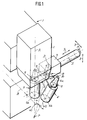
- 1 denotes a conventional universal drilling and milling machine, which has a vertical work spindle 3 in a vertically displaceable spindle housing 2. Only the axis A of this work spindle is shown in FIG. 1.
- the universal drilling and milling machine can also have a horizontal work spindle, of which, however, only its axis is shown in FIG. 1 and designated by B.
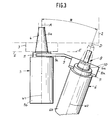
- the vertical and horizontal work spindles each have a tool holder that e.g. can be designed as steep taper receptacle 4, as shown in Figure 3.
- different tools 5, 6 are to be inserted one after the other into this tool holder.
- the tool changer according to the invention is provided for this purpose.
- This has a carrier 7 which, in the exemplary embodiment shown, can be pivoted about the pivot axis S in a bearing arm (not shown).
- the pivot axis S is arranged perpendicular to a plane which runs through the axes A and B of the two work spindles arranged perpendicular to one another.
- the carrier 7 can also be displaced in the direction Z parallel to the spindle axis A and in the direction Y parallel to the spindle axis B. Further possibilities of movement of the wearer can be provided to transfer the tools into a magazine, not shown, or to remove them from the magazine.
- an interchangeable head 8 is pivotally mounted about an axis of rotation D.
- the interchangeable head 8 has two gripper arms 9, 10 which are offset by 90 ° with respect to the axis of rotation D.
- the offset of the two gripper arms 9, 10 to one another by 90 ° or less has the advantage that the gripper head only has to be pivoted by 90 ° or less each time the tool is changed, which results in shorter change times. If this advantage is dispensed with, the gripper arms 9, 10 can optionally also be arranged diametrically to one another.
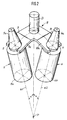
- the free ends 9a and 10a of each gripper arm are angled with respect to the axis of rotation D and carry known grippers 11, which are, however, only indicated schematically.
- the free ends 9a, 10a of the gripper arms 9, 10 are angled with respect to the axis of rotation D such that the two tool axes W1 and W2 of the tools gripped by the grippers 11 and the axis of rotation D intersect at a single point P.
- Each of the tool axes W1 and W2 includes an acute angle ⁇ with the axis of rotation of approximately 10-30 °. This angle is preferably approximately 20 °.
- the free ends 9a and 10a of the gripper arms 9, 10 are further angled with respect to the axis of rotation D such that the tool axes W1 and W2 of the tools 5, 6 gripped by the grippers 11 diverge toward their clamping ends 5a, 6a.
- the clamping ends 5a, 6a of the tools 5, 6 are adapted to the tool holder of the machine tool. For example, it can be a steep taper or any customary configuration of a clamping end of a tool.
- the working ends 5b and 6b of the tools 5, 6 which carry the cutting edges converge to one another the more, the further they are from the grippers 11.
- the axis of rotation D is arranged in the carrier 7 in such a way that when the respective tool is actually inserted or exchanged into the receptacle of the respective spindle, whose axis A or B intersects, as shown in FIG. The point P then also lies on the axis A or B.
- the axis of rotation D encloses with the respective axis A or B of the receptacle into which a tool is to be inserted or exchanged, an angle ⁇ which corresponds to the acute angle ⁇ , which include the tool axes W1 and W2 with the axis of rotation D.
- the change process takes place in the following way: With the gripper arranged on the gripper arm 10, the gripping head 8 has removed the tool 6 from the magazine (not shown).
- the carrier 7 is displaced in the direction X of its pivot axis S until the gripper 11 arranged on the gripper arm 9 is located in the region of the vertical work spindle contained in the spindle housing 2.
- the gripper 11 grips the tool 5 clamped in the vertical working spindle.
- the carrier 7 then executes a vertical movement in the direction Z, ie exactly in the direction of the spindle axis A. As a result, he removes the tool 5 from the work spindle.
- the clamping end 6a of the tool to be changed is located below the clamping end 5a of the tool 5 located in the work spindle 3. This prevents collisions of the clamping end 6a with the spindle housing 2 during the changing process.
Landscapes
- Engineering & Computer Science (AREA)
- Mechanical Engineering (AREA)
- Automatic Tool Replacement In Machine Tools (AREA)
Applications Claiming Priority (2)
| Application Number | Priority Date | Filing Date | Title |
|---|---|---|---|
| DE4111307A DE4111307C1 (enExample) | 1991-04-08 | 1991-04-08 | |
| DE4111307 | 1991-04-08 |
Publications (1)
| Publication Number | Publication Date |
|---|---|
| EP0508087A1 true EP0508087A1 (de) | 1992-10-14 |
Family
ID=6429053
Family Applications (1)
| Application Number | Title | Priority Date | Filing Date |
|---|---|---|---|
| EP92103436A Withdrawn EP0508087A1 (de) | 1991-04-08 | 1992-02-28 | Werkzeugwechsler |
Country Status (3)
| Country | Link |
|---|---|
| EP (1) | EP0508087A1 (enExample) |
| JP (1) | JPH05208332A (enExample) |
| DE (2) | DE4111307C1 (enExample) |
Families Citing this family (2)
| Publication number | Priority date | Publication date | Assignee | Title |
|---|---|---|---|---|
| DE9213786U1 (de) * | 1992-10-13 | 1994-02-10 | Ott Maschinentechnik Gmbh, 87663 Lengenwang | Werkzeugwechsler |
| KR101856198B1 (ko) * | 2011-12-26 | 2018-05-11 | 두산공작기계 주식회사 | 공구 교환 제어 장치 및 그 방법 |
Family Cites Families (2)
| Publication number | Priority date | Publication date | Assignee | Title |
|---|---|---|---|---|
| DE3136612A1 (de) * | 1981-09-15 | 1983-03-31 | Schwäbische Hüttenwerke GmbH, 7080 Aalen | Fraes- und/oder bohrmaschine |
| DE8407327U1 (de) * | 1984-03-09 | 1984-12-06 | Friedrich Deckel AG, 8000 München | Einrichtung zum einwechseln von werkzeugen oder dgl. in die arbeitsspindel einer werkzeugmaschine |
-
1991
- 1991-04-08 DE DE4111307A patent/DE4111307C1/de not_active Expired - Lifetime
- 1991-04-08 DE DE9104223U patent/DE9104223U1/de not_active Expired - Lifetime
-
1992
- 1992-02-28 EP EP92103436A patent/EP0508087A1/de not_active Withdrawn
- 1992-04-06 JP JP4083974A patent/JPH05208332A/ja active Pending
Non-Patent Citations (2)
| Title |
|---|
| PATENT ABSTRACTS OF JAPAN vol. 13, no. 335 (M-856)(3683) 27. Juli 1989 & JP-A-1 115 540 ( HITACHI SEIKI CO LTD ) 8. Mai 1989 * |
| PATENT ABSTRACTS OF JAPAN vol. 8, no. 128 (M-302)(1565) 14. Juni 1984 & JP-A-59 030 641 ( NIIGATA TEKKOSHO K.K. ) 18. Februar 1984 * |
Also Published As
| Publication number | Publication date |
|---|---|
| DE9104223U1 (de) | 1992-08-13 |
| DE4111307C1 (enExample) | 1992-06-25 |
| JPH05208332A (ja) | 1993-08-20 |
Similar Documents
| Publication | Publication Date | Title |
|---|---|---|
| EP1260294B1 (de) | Verfahren und Vorrichtung zur Drehbearbeitung | |
| EP1260307B1 (de) | Werkzeugmaschine und Verfahren zur Bearbeitung eines stangenförmigen Werkstücks | |
| EP3195976B1 (de) | Werkzeugmaschine, insbesondere mehrfachspindel-fräsmaschine | |
| EP1027955B1 (de) | Werkzeugmaschine | |
| EP0204151B2 (de) | Werkzeugmaschine | |
| EP1338376A1 (de) | Fräsmaschine zur Fräs- und Drehbearbeitung von Stangenmaterial | |
| EP0297034A2 (de) | Magazin mit Wechselvorrichtung | |
| EP0885686B1 (de) | Bearbeitungszelle | |
| EP0186726B1 (de) | Werkzeugmagazin | |
| DE19854276C2 (de) | Werkzeugmaschinen-Anordnung mit einer Vorrichtung für einen automatischen Werkzeugwechsel | |
| EP0154349B1 (de) | Einrichtung zum Einwechseln von Werkzeugen oder dergleichen in die Arbeitsspindel einer Werkzeugmaschine | |
| EP0310128A2 (de) | Werkzeugwechselsystem | |
| DE3632319C2 (enExample) | ||
| DE4236866A1 (de) | Drehmaschine | |
| DE10310997A1 (de) | Mehrspindeldrehmaschine | |
| EP1511596A1 (de) | Mehrspindelwerkzeugmaschine | |
| DE2517759A1 (de) | Mehrspindeldrehautomat | |
| DE3634018C2 (enExample) | ||
| DE29821047U1 (de) | Werkzeugmaschinen-Anordnung mit einer Vorrichtung für einen automatischen Werkzeugwechsel | |
| EP0508087A1 (de) | Werkzeugwechsler | |
| DE3717016C2 (enExample) | ||
| DE19936468A1 (de) | Drehmaschine | |
| EP0467253A2 (de) | Drehmaschine | |
| EP0137117A2 (de) | Werkzeugwechselvorrichtung mit einer Übergabeeinrichtung für Werkzeugträger | |
| DE2950934C2 (de) | Flexibles Fertigungssystem mit einer zentralen, eine vertikale Schaltachse und eine horizontale Werkzeug-Antriebsachse aufweisenden Revolverkopf-Bearbeitungseinheit |
Legal Events
| Date | Code | Title | Description |
|---|---|---|---|
| PUAI | Public reference made under article 153(3) epc to a published international application that has entered the european phase |
Free format text: ORIGINAL CODE: 0009012 |
|
| AK | Designated contracting states |
Kind code of ref document: A1 Designated state(s): AT CH ES FR GB IT LI SE |
|
| 17P | Request for examination filed |
Effective date: 19930209 |
|
| 17Q | First examination report despatched |
Effective date: 19930518 |
|
| STAA | Information on the status of an ep patent application or granted ep patent |
Free format text: STATUS: THE APPLICATION IS DEEMED TO BE WITHDRAWN |
|
| 18D | Application deemed to be withdrawn |
Effective date: 19960830 |