EP0507992A2 - Séparateur d'air dans une installation de mesure de lait - Google Patents
Séparateur d'air dans une installation de mesure de lait Download PDFInfo
- Publication number
- EP0507992A2 EP0507992A2 EP91120727A EP91120727A EP0507992A2 EP 0507992 A2 EP0507992 A2 EP 0507992A2 EP 91120727 A EP91120727 A EP 91120727A EP 91120727 A EP91120727 A EP 91120727A EP 0507992 A2 EP0507992 A2 EP 0507992A2
- Authority
- EP
- European Patent Office
- Prior art keywords
- milk
- air separator
- air
- funnel
- bluff body
- Prior art date
- Legal status (The legal status is an assumption and is not a legal conclusion. Google has not performed a legal analysis and makes no representation as to the accuracy of the status listed.)
- Granted
Links
- 239000008267 milk Substances 0.000 title claims abstract description 28
- 210000004080 milk Anatomy 0.000 title claims abstract description 28
- 235000013336 milk Nutrition 0.000 title claims abstract description 28
- 238000009434 installation Methods 0.000 title 1
- 238000011144 upstream manufacturing Methods 0.000 claims description 2
- 238000005259 measurement Methods 0.000 abstract description 3
- 230000015572 biosynthetic process Effects 0.000 description 1
- 238000006073 displacement reaction Methods 0.000 description 1
- 239000006260 foam Substances 0.000 description 1
- 230000000630 rising effect Effects 0.000 description 1
Images
Classifications
-
- B—PERFORMING OPERATIONS; TRANSPORTING
- B01—PHYSICAL OR CHEMICAL PROCESSES OR APPARATUS IN GENERAL
- B01D—SEPARATION
- B01D19/00—Degasification of liquids
- B01D19/0042—Degasification of liquids modifying the liquid flow
- B01D19/0052—Degasification of liquids modifying the liquid flow in rotating vessels, vessels containing movable parts or in which centrifugal movement is caused
- B01D19/0057—Degasification of liquids modifying the liquid flow in rotating vessels, vessels containing movable parts or in which centrifugal movement is caused the centrifugal movement being caused by a vortex, e.g. using a cyclone, or by a tangential inlet
Definitions
- the invention relates to an air separator in a milk measuring system in the form of a container with an outlet arranged in the region of its base and an inlet connection opening, in particular tangentially, in its upper region.
- the object of the invention is to improve the performance of the air separator.
- a funnel is arranged upstream of the inlet nozzle, which widens towards the inlet nozzle up to its cross section, and that a bluff body sits in the inlet nozzle directly behind the funnel.
- the bluff body is preferably designed as a plug with a multiplicity of parallel channels.
- the flow rate of the milk flowing into the air separator is reduced immediately before it enters the air separator.
- the bluff body ensures that the funnel fills over its entire cross-section.
- the bluff body ensures that the milk leaving it is distributed over the entire cross-section of the nozzle. This distribution is preferably carried out via the parallel channels. Another distribution, for example via sieves, is also possible.
- the milk measuring system can be operated with a higher throughput without the milk having a higher proportion of the air inclusions than in conventional systems at this higher output, or that has a lower proportion of air pockets with the same throughput.
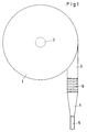
- the air separator 1 is designed as a closed, cylindrical container 1 with an outlet 2 arranged in its base and an inlet connection 3 opening tangentially into the container 1. Not shown, but is generally known that such an air separator can be equipped approximately halfway up with an annular displacement body, which has an annular gap with the wall of the container 1 for the passage of milk and an opening in the middle for a float, via which in Depending on the level in the container, a valve of the milk measuring system arranged in the outlet 2 is controlled.
- the inlet connection 3 is preceded by a funnel 4 which widens in cross-section towards the inlet connection 3 and is connected with its inlet, which is small in cross-section, to a hose or a line via which the milk accepted is conveyed.
- a bluff body 6 which occupies the entire cross section of the inlet nozzle 3.
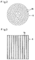
- this bluff body 6 is designed as a plug with a large number of axial, parallel channels 6a.
- the funnel 4 in cooperation with the bluff body 6, causes the milk conveyed via the line 5 to be distributed over the entire cross section of the funnel 4 due to the congestion, so that its flow speed in the direction of the container 1 is constantly reduced in accordance with the cross-sectional expansion.
- the axial, parallel channels 6a cause a laminar flow which is distributed over the entire cross section of the inlet connection 5 to occur at the outlet of the bluff body 6. Because of this laminar flow of reduced speed, there is no flow turbulence when the milk flows into the container 1, which results in further air inclusion.
- the funnel 4 and the bluff body 6 ensure that the milk to be freed of air inclusions in the container 1 has a lower proportion of air inclusions compared to milk that enters the container 1 with an air separator without the funnel 4 and bluff body 6.
Landscapes
- Chemical & Material Sciences (AREA)
- Chemical Kinetics & Catalysis (AREA)
- Dairy Products (AREA)
- Sampling And Sample Adjustment (AREA)
- Degasification And Air Bubble Elimination (AREA)
- Confectionery (AREA)
Applications Claiming Priority (2)
| Application Number | Priority Date | Filing Date | Title |
|---|---|---|---|
| DE4111280 | 1991-04-08 | ||
| DE4111280A DE4111280C1 (fr) | 1991-04-08 | 1991-04-08 |
Publications (3)
| Publication Number | Publication Date |
|---|---|
| EP0507992A2 true EP0507992A2 (fr) | 1992-10-14 |
| EP0507992A3 EP0507992A3 (en) | 1992-12-16 |
| EP0507992B1 EP0507992B1 (fr) | 1994-09-14 |
Family
ID=6429039
Family Applications (1)
| Application Number | Title | Priority Date | Filing Date |
|---|---|---|---|
| EP91120727A Expired - Lifetime EP0507992B1 (fr) | 1991-04-08 | 1991-12-03 | Séparateur d'air dans une installation de mesure de lait |
Country Status (5)
| Country | Link |
|---|---|
| EP (1) | EP0507992B1 (fr) |
| AT (1) | ATE111372T1 (fr) |
| CS (1) | CS56692A3 (fr) |
| DE (1) | DE4111280C1 (fr) |
| PL (1) | PL294000A1 (fr) |
Family Cites Families (6)
| Publication number | Priority date | Publication date | Assignee | Title |
|---|---|---|---|---|
| GB918105A (en) * | 1958-05-05 | 1963-02-13 | Proctor & Gamble Ltd | A process for de-gassing aqueous solutions and the like |
| DE1128216B (de) * | 1961-06-23 | 1962-04-19 | Dipl Landw Heinrich Hamberger | Vorrichtung zum Foerdern von Milch |
| US3771290A (en) * | 1971-12-06 | 1973-11-13 | Armstrong Ltd S A | Vortex de-aerator |
| DE2437306C2 (de) * | 1974-08-02 | 1980-06-12 | Walter Jansky Tank- & Apparatebau 4407 Emsdetten | Vorrichtung zum messen von milch |
| AU531076B2 (en) * | 1980-11-04 | 1983-08-11 | Tosco Corp. | Foam separation |
| DE3505466C1 (de) * | 1985-02-16 | 1986-04-30 | Otto Tuchenhagen GmbH & Co KG, 2059 Büchen | Vorrichtung zur Gasabscheidung aus Milch und Abgrenzung von Milchmengen |
-
1991
- 1991-04-08 DE DE4111280A patent/DE4111280C1/de not_active Expired - Fee Related
- 1991-12-03 EP EP91120727A patent/EP0507992B1/fr not_active Expired - Lifetime
- 1991-12-03 AT AT91120727T patent/ATE111372T1/de not_active IP Right Cessation
-
1992
- 1992-02-26 CS CS92566A patent/CS56692A3/cs unknown
- 1992-03-27 PL PL29400092A patent/PL294000A1/xx unknown
Also Published As
| Publication number | Publication date |
|---|---|
| DE4111280C1 (fr) | 1992-11-26 |
| EP0507992B1 (fr) | 1994-09-14 |
| ATE111372T1 (de) | 1994-09-15 |
| PL294000A1 (en) | 1992-10-19 |
| EP0507992A3 (en) | 1992-12-16 |
| CS56692A3 (en) | 1992-10-14 |
Similar Documents
| Publication | Publication Date | Title |
|---|---|---|
| DE2818791C2 (de) | Axial durchströmter Zyklonabscheider | |
| DE102010051594B4 (de) | Gaszähler | |
| DE4013351C2 (fr) | ||
| DE69112836T2 (de) | Wirbelstromventil. | |
| DE2328220A1 (de) | Vorrichtung und verfahren zur erzeugung eines wirbels | |
| DE69305301T2 (de) | Einrichtung zur Regelung und Verteilung einer mehrphasigen Flüssigkeit | |
| EP0416146B1 (fr) | Dispositif pour la séparation de particules solides et de fluides à densité élevée à partir de fluide à densité plus faible | |
| DE3002578C2 (de) | Vorrichtung zum Entgasen einer Flüssigkeit | |
| DE3333261C2 (de) | Vorrichtung zum pneumatischen oder hydraulischen Fördern von Schüttgut | |
| EP1496240A2 (fr) | Système de séparation | |
| EP0507992B1 (fr) | Séparateur d'air dans une installation de mesure de lait | |
| DE2058395A1 (de) | Siebvorrichtung zum Abscheiden von Feststoffen aus Fluessigkeitsstroemen in Rohrleitungen | |
| DE69701288T2 (de) | Vorrichtung zur beseitigung von kugeln aus einer kühlmittelleitung | |
| DE3101221A1 (de) | "einrichtung zur schaumflotation" | |
| AT398681B (de) | Einrichtung zum abzweigen von teilmengen aus einem durch eine rohrleitung fliessenden milchstrom | |
| DE2260729B1 (de) | Abscheideelement für eine Vorrichtung zum Abscheiden von Flüssigkeiten oder Feststoffen aus einem gasförmigen Medium oder Feststoffen aus einem flüssigen Medium | |
| DE19651857C1 (de) | Vorrichtung zur Abscheidung von Feststoffen aus staubbeladenen Abgasen, insbesondere von Verbrennungsanlagen | |
| DE102023118066A1 (de) | Hydraulisches Leitungssystem zum zumindest teilweisen Separieren und Formgebungsmaschine sowie Verfahren hierzu | |
| DE29719677U1 (de) | Durchflußmeßgerät | |
| AT255706B (de) | Luftabscheider, insbesondere für eine mit einer Umwälzpumpe betriebene Heizungsanlage | |
| DE2431876B2 (de) | Verfahren zum Abscheiden von Flüssigkeiten aus einem Gasstrom unter Einwirkung von Fliehkraft innerhalb einer Drallströmung und eine Vorrichtung zur Durchführung dieses Verfahrens | |
| DE9200219U1 (de) | Filter-Sicherheitskombination | |
| DE202006013661U1 (de) | Filtrationssystem mit Belüftungssystem | |
| DE3537352C2 (fr) | ||
| DE29723843U1 (de) | Vorrichtung zum Abscheiden von Feststoffen aus einem Trägerstrom |
Legal Events
| Date | Code | Title | Description |
|---|---|---|---|
| PUAI | Public reference made under article 153(3) epc to a published international application that has entered the european phase |
Free format text: ORIGINAL CODE: 0009012 |
|
| AK | Designated contracting states |
Kind code of ref document: A2 Designated state(s): AT BE CH DE DK ES FR GB GR IT LI LU NL SE |
|
| PUAL | Search report despatched |
Free format text: ORIGINAL CODE: 0009013 |
|
| AK | Designated contracting states |
Kind code of ref document: A3 Designated state(s): AT BE CH DE DK ES FR GB GR IT LI LU NL SE |
|
| 17P | Request for examination filed |
Effective date: 19930119 |
|
| 17Q | First examination report despatched |
Effective date: 19940113 |
|
| RBV | Designated contracting states (corrected) |
Designated state(s): AT BE CH DK ES FR GB GR IT LI LU NL SE |
|
| GRAA | (expected) grant |
Free format text: ORIGINAL CODE: 0009210 |
|
| REG | Reference to a national code |
Ref country code: DE Ref legal event code: 8566 |
|
| AK | Designated contracting states |
Kind code of ref document: B1 Designated state(s): AT BE CH DK ES FR GB GR IT LI LU NL SE |
|
| PG25 | Lapsed in a contracting state [announced via postgrant information from national office to epo] |
Ref country code: IT Free format text: LAPSE BECAUSE OF FAILURE TO SUBMIT A TRANSLATION OF THE DESCRIPTION OR TO PAY THE FEE WITHIN THE PRE;WARNING: LAPSES OF ITALIAN PATENTS WITH EFFECTIVE DATE BEFORE 2007 MAY HAVE OCCURRED AT ANY TIME BEFORE 2007. THE CORRECT EFFECTIVE DATE MAY BE DIFFERENT FROM THE ONE RECORDED.SCRIBED TIME-LIMIT Effective date: 19940914 Ref country code: ES Free format text: THE PATENT HAS BEEN ANNULLED BY A DECISION OF A NATIONAL AUTHORITY Effective date: 19940914 Ref country code: FR Effective date: 19940914 Ref country code: BE Effective date: 19940914 Ref country code: NL Effective date: 19940914 Ref country code: GB Effective date: 19940914 Ref country code: GR Free format text: LAPSE BECAUSE OF FAILURE TO SUBMIT A TRANSLATION OF THE DESCRIPTION OR TO PAY THE FEE WITHIN THE PRESCRIBED TIME-LIMIT Effective date: 19940914 Ref country code: DK Effective date: 19940914 |
|
| REF | Corresponds to: |
Ref document number: 111372 Country of ref document: AT Date of ref document: 19940915 Kind code of ref document: T |
|
| PG25 | Lapsed in a contracting state [announced via postgrant information from national office to epo] |
Ref country code: AT Effective date: 19941203 |
|
| PG25 | Lapsed in a contracting state [announced via postgrant information from national office to epo] |
Ref country code: SE Effective date: 19941214 |
|
| PG25 | Lapsed in a contracting state [announced via postgrant information from national office to epo] |
Ref country code: LI Effective date: 19941231 Ref country code: LU Free format text: LAPSE BECAUSE OF NON-PAYMENT OF DUE FEES Effective date: 19941231 Ref country code: CH Effective date: 19941231 |
|
| EN | Fr: translation not filed | ||
| NLV1 | Nl: lapsed or annulled due to failure to fulfill the requirements of art. 29p and 29m of the patents act | ||
| GBV | Gb: ep patent (uk) treated as always having been void in accordance with gb section 77(7)/1977 [no translation filed] |
Effective date: 19940914 |
|
| PLBE | No opposition filed within time limit |
Free format text: ORIGINAL CODE: 0009261 |
|
| STAA | Information on the status of an ep patent application or granted ep patent |
Free format text: STATUS: NO OPPOSITION FILED WITHIN TIME LIMIT |
|
| REG | Reference to a national code |
Ref country code: CH Ref legal event code: PL |
|
| 26N | No opposition filed |