EP0507740B1 - Weft handling method and a weft handling device for carrying out the same on a jet loom - Google Patents
Weft handling method and a weft handling device for carrying out the same on a jet loom Download PDFInfo
- Publication number
- EP0507740B1 EP0507740B1 EP19920810235 EP92810235A EP0507740B1 EP 0507740 B1 EP0507740 B1 EP 0507740B1 EP 19920810235 EP19920810235 EP 19920810235 EP 92810235 A EP92810235 A EP 92810235A EP 0507740 B1 EP0507740 B1 EP 0507740B1
- Authority
- EP
- European Patent Office
- Prior art keywords
- weft
- mispicked
- nozzle
- fluid
- handling device
- Prior art date
- Legal status (The legal status is an assumption and is not a legal conclusion. Google has not performed a legal analysis and makes no representation as to the accuracy of the status listed.)
- Expired - Lifetime
Links
Images


Classifications
-
- D—TEXTILES; PAPER
- D03—WEAVING
- D03D—WOVEN FABRICS; METHODS OF WEAVING; LOOMS
- D03D51/00—Driving, starting, or stopping arrangements; Automatic stop motions
- D03D51/06—Driving, starting, or stopping arrangements; Automatic stop motions using particular methods of stopping
- D03D51/08—Driving, starting, or stopping arrangements; Automatic stop motions using particular methods of stopping stopping at definite point in weaving cycle, or moving to such point after stopping
- D03D51/085—Extraction of defective weft
Definitions
- the present invention relates to a method of handling a weft on a jet loom that picks a weft by the jetting action of a main picking nozzle, comprising cutting off a portion of the weft continuous with a mispicked weft from a portion of the weft continuous therewith and extending in the main picking nozzle, and removing the portion of the weft cut off the portion of the weft.extending in the main picking nozzle, and relates to a weft handling device for carrying out the method.
- a weft handling device for a jet loom, capable of automatically extracting a mispicked weft.
- the weft handling device guides the weft continuously with the mispicked weft into a weft guide duct and a suction duct disposed above a main picking nozzle, grips the weft continuous with the mispicked weft between a pair of rollers, and draws the weft by the pair of rollers through the weft guide duct into the suction duct to extract the mispicked weft from a shed.
- the weft As the weft extending from a weft measuring device and through the main picking nozzle is drawn, the weft becomes taut between the rollers and the main picking nozzle, the taut weft is pressed against a cutting blade disposed directly above the front tip of the main picking nozzle to cut the weft off the mispicked weft and to separate the weft from the main picking nozzle.
- the weft As the weft is drawn by the rollers, the mispicked weft is extracted from the shed, and then, the extracted mispicked weft is removed from the suction duct.
- a weft handling device disclosed in Japanese Patent Laid-open No. Sho 61-252342 also extracts a mispicked weft from the shed by drawing the weft.
- This weft handling device extracts the mispicked weft only by an air current that flows from a blow nozzle to a suction nozzle.
- the blow nozzle and the suction nozzle are disposed opposite to each other respectively on the opposite sides of the main picking nozzle.
- An air blowing circuit provided with a solenoid valve is connected to the main picking nozzle, and the solenoid valve is controlled for on-off operation according to the operating condition of the loom to blow air moderately through the main picking nozzle.
- Both the prior art weft handling devices have a problem that a portion of the weft extending between the weft measuring device and the main picking nozzle is pulled off the main picking nozzle by tensile pull of the cutting blade acting on the weft in cutting the weft during a mispicked weft extracting process. If coils of the weft reserved on a weft measuring and storing device are disheveled by the tensile pull, it is possible that the first; pick after restarting the loom fails.
- the weft handling device disclosed in Japanese Patent Laid-open No. Sho 61-252342 execute moderate blowing control operation to blowing air moderately through the main picking nozzle only during the adjustment of the phase of the weft measuring drum. Troubles occur if moderate air blowing is continued through out a mispicked weft extracting process; it is possible that the weft sucked into and held in the suction nozzle by suction is pulled out from the suction nozzle and blown in disheveled loops into the shed or the weft is untwisted and disintegrated by blowing if the weft is exposed to blowing for a long time. Such troubles can be prevented by limited air blowing operation for blowing air only for a limited time. However, limited air blowing operation is unable to obviate the adverse action of the tension created in the weft in cutting the weft.
- a weft handling method in accordance with the present invention applies a fluid jet, in synchronism with the timing of cutting off a portion of a weft continuous with a mispicked weft from a portion of the weft extending in the main picking nozzle, to the portion of the weft extending in the main picking nozzle before a cutting position where the weft is to be cut so as to neutralize the effect of tensile pull acting on the portion of the weft extending in the main picking nozzle by the counteracting force of the fluid jet in cutting the weft.
- a weft handling device in accordance with the present invention comprises a weft cutting means for cutting a portion of a weft continuous with a mispicked weft from a portion of the weft continuous therewith and extending in the main picking nozzle of a jet Ioom, and a fluid blowing means for blowing a fluid into the main picking nozzle in synchronism with the cutting operation of the weft cutting means.
- the weft handling device pulls the portion of the weft continuous with a mispicked weft and, consequently, a portion of the weft extending between the weft measuring device and the main picking nozzle of the jet loom is tensioned. Then, the fluid blowing means blows a fluid into the main picking nozzle.in synchronism with the weft cutting operation of the weft cutting means for cutting the taut weft so that the effect of tensile pull acting on the weft is neutralized by the counteracting force of the fluid jet. Accordingly, the portion of the weft extending in the main picking nozzle is kept from falling off the main picking nozzle and coils of the weft wound on the storage drum of the weft measuring and storing device are kept from being disheveled.
- the weft handling device draws the weft by the drawing mechanism comprising the driving roller, the motor for driving the driving roller for rotation, the driven roller and the pneumatic cylinder actuator interlocked with the driven roller.
- the fluid blowing means is included in a pressurized fluid supply system for supplying a pressurized fluid to the pneumatic cylinder actuator in bringing the driven roller into engagement with the driving roller.
- the weft handling device Since the pressurized fluid supply system functions for both supplying the pressurized fluid to the pneumatic cylinder actuator and supplying the pressurized fluid to the main picking nozzle, the weft handling device need not be provided with any special air supply tank, so that the weft handling device has a simple construction.
- Fig 1 to 7 show the following:
- a main picking nozzle 2 is fixed to one end of a sley 1, and a reed 3 capable of guiding a picked weft is attached to the sley i.
- the weft Y is wound and stored on the storage drum 4a of a drum type weft measuring and storing device.4 is guided into the main picking nozzle 2.
- the weft Y is picked through a weft guide passage, not shown, formed by the dents of the reed 3 by a fluid jet jetted by the main picking nozzle 2 in synchronism with picking timing.
- a weft cutting device 5 is disposed near the main picking nozzle 2 at a position on the extension of the cloth fell of.the fabric on the jet loom to cut the weft Y after every insertion of the weft Y as a pick into the shed.
- a pneumatic cylinder actuator 7 is disposed near the weft cutting device 5 to keep the weft cutting device 5 from weft cutting operation.
- a mispicked weft detecting device 6 is disposed on the other end of the sley 1, i.e., the weft arriving side of the sley 1.
- a weft guide duct 8, an air guide 9 and a suction duct lg are disposed above the main picking nozzle 2:
- a cutting blade 22 is disposed directly above the front tip of the main picking nozzle 2. Air is blown into the suction duct 10 through a nozzle 10a to generate a suction within the suction nozzle 10.
- a blow nozzle 11 is disposed in front of the main picking nozzle under a picking passage so as to blow air into the inlet opening 8a of the weft guide duct 8.
- the weft guide duct 8, the air guide 9, the suction duct 10 and the blow nozzle 11 move along a circular path according to the swing motion of the sley 1.
- a driving roller 13 and a driven roller 15 are disposed so that the weft guide duct 8 and the air guide duct 9 are located respectively on the opposite sides of a line passing the centers of the driving roller 13 and the driven roller 15 when the sley 1 is at a position corresponding to a crank angle of about 180°.
- the driving roller 13 is driven for rotation by a motor 12, and the driven roller 15 is shifted between a working position where the same is pressed against the driving roller 13 and a standby position where the same is separated from the driving roller by a pneumatic cylinder actuator 14.
- a weft detector 16 such as a sensitive switch, is disposed above a position between the air guide 9 and the suction duct 10.
- the weft detector 16 is attached to the pneumatic cylinder actuator 14 so that its actuator 16a is inserted between the air guide 9 and the suction duct 10 when the driven roller 15 is shifted from the standby position to the working position by the pneumatic cylinder actuator 14.
- the pneumatic cylinder actuator 7 for stopping the operation of the weft cutting device 5 is connected through a solenoid valve 17 to a compressed air tank 21.
- the compressed air tank 21 is connected through a solenoid valve 18 to the blow nozzle 11, through a solenoid valve 19 to the blow nozzle 10a of the suction duct 10 and through a solenoid valve 20 to the pneumatic cylinaer actuator 14.
- the main picking nozzle 2 is connected through a tee joint 31 and a solenoid valve 32 to a high-pressure cornpressed air tank 33, and through the tee joint 31 and a sole1ioid valve 34 to a low-pressure compressed air tank 35.
- the high pressure compressed air tank 33 supplies high-pressure compressed air to the main picking nozzle 2 for picking.
- the low-pressure compressed air tank 35 supplies low-pressure compressed air of a pressure lower than that of the high-pressure compressed air to the main picking nozzle 2.
- a control unit 24 for controlling the weft handling device is supported on a bracket, not shown, supporting jack levers for vertically moving heddle frames 23. Data is transferred between the control unit 24 and a computer 25 for controlling weaving operation.
- the control unit,24 controls the motor 12 and the solenoid valve 20 on the basis of the output signal of the weft detector 16.
- the computer 25 controls the solenoid valves 17, 18, 19, 32 and 34, and a main motor, not shown, on the basis of a mispicked weft detection signal provided by the mispicked weft detecting device 6 and the output signal of a crank angle detecting encoder 27.
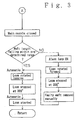
- Figs. 2 and 3 are flow charts of a mispicked weft disposal program.
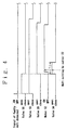
- a mispicked weft disposal operation is carried out according to the program shown in Figs. 2 and 3, and a timing chart shown in Fig. 4.
- the mispicked weft detecting device 6 Upon the detection of a mispicked weft, the mispicked weft detecting device 6 provides a mispicked weft detection signal. Upon the reception of the mispicked weft detection signal, the computer 25 provides a stop signal to.stop the jet loom and.signals to open the solenoid valves 17, 18 and 19. Consequently, the weft cutting device 5 is held inoperative, air is blown through the blow nozzle 11 during the inertial running of the jet loom and a partial vacuum is created within the suction duct 10.
- the mispicked weft Yb beaten up to the cloth fell remains continuous with the weft Y1, the weft Y1 continuous with the mispicked weft Yb is not picked, the weft Y1 is guided into the weft guide duct 8, the weft Y1 is sucked by the suction duct 10 so as to extend in the detection range of the weft detector 16.
- the main motor is reversed to locate the sley 1 at a position corresponding to a crank angle of 180°, i.e., the back dead center, so that a maximum shed is formed to release the mispicked weft Yb from the warps.
- the solenoid valve 18 is closed to stop blowidg air through the blow nozzle 11.
- the solenoid valve 20 is opened to project the piston rod of the pneumatic cylinder actuator 14 in order that the driven roller 15 is shifted from the standby position to the working position to hold the weft Y1 between the driving roller 13 and the driven roller 15.
- the actuator 16a of the weft detector 16 engages the weft Y1 to turn on the weft detector 16.
- the control unit 24 opens the solenoid valve 34 upon the reception of a weft detection signal from the weft detector 16 to blow low-pressure compressed air through the main picking nozzle 2 for a predetermined time T1.
- the pressure of the low-pressure compressed air is adjusted to a relatively low pressure so that the weft Y1 is not disintegrated by the low-pressure compressed air.
- the predetermined time T1 is a relatively short time in which the weft Y1 is not untwisted by the low-pressure compressed air.
- the motor 12 is actuated to start rotating the rollers 13 and 15 to draw the weft Y1 with a slight time lag after starting blowing the low-pressure compressed air through the main picking nozzle 2.
- the weft Y1 is drawn by the rollers 13 and 15, the weft Y1 is tensioned between the rollers 13 and 15, and the main picking nozzle 2, so that the weft Y1 is pressed'agairist and cut with the cutting blade 22.
- the weft Y i.e., a portion of the weft Y1 extending from the weft measuring and storing device 4
- the weft Y is prevented from recoiling by the low-pressure compressed air being blown through the main picking nozzle 2 in a direction opposite to the recoiling direction, so that the weft Y is unable to recoil toward the weft measuring and storing device 4.
- the weft Y remains in the main picking nozzle 2 and coils of the weft Y on the storage drum 4a of the weft measuring and storing device 4 are not disheveled.
- the solenoid valve 34 is closed to stop blowing the low-pressure compressed air through the main picking nozzle 2.
- the weft Y1 separated from the weft Y is drawn through the weft guide duct 8 by the rollers 13 and 15 and sucked into the suction duct 10 by the suction of the suction duct 10, and thereby the mispicked weft Yb continuous with the weft Y1 is extracted from the shed.
- the actuator 16a of the weft detector 16 Upon the passage of the mispicked weft Yb past the rollers 13 and 15, the actuator 16a of the weft detector 16 returns to its OFF position.
- the control unit 24 measures the length of the mispicked weft Yb extracted from the shed on the basis of the rotation of the motor 12 represented by rotation data provided by the rotary encoder 12a.during a period from the start of the motor 12 and the termination of the weft detection signal of the weft detector 16.
- the control unit 24 decides that the mispicked weft extracting operation has successfully been completed and gives a restart signal to the computer 25. Then, the computer 25 reverses the jet loom to locate the sley 1 at a position appropriate to restarting the jet loom, i.e., a position corresponding to a crank angle of 300°, closes the solenoid vaive 17 to make the weft cutting device 5 operative, and then, restarts the jet loom.
- the control unit 24 gives, to the computer 25, a failure signal indicating that the mispicked weft extracting operation is unsuccessful and flickers a failure indicating lamp 26.
- the computer 25 drives the main motor in the normal direction to locate the sley 1 at a position corresponding to a crank angle of 300°.
- the operator moves the sley 1 to a position corresponding to a crank angle of 180° to form a maximum shed, extracts the mispicked weft, and then restarts the jet loom.
- the shed is closed to allow the warps to relax so that the warps are not tensioned excessively. Accordingly, stopping marks are not formed in the fabric after the jet loom has been restarted.
- the main shaft of the jet loom is rotated in the normal direction in closing the shed by setting the crank angle to 300° to prevent the warps and the weft from being interlaced.
- Second Embodiment As shown in Fig. 5, the construction of a weft handling device in a second embodiment according to the present invention is substantially the same as that of the weft handling device in the first embodiment, except that a high-pressure compressed air supply system employed in the second embodiment is different from that employed in the first embodiment. Referring to Fig. 5, the construction of a weft handling device in a second embodiment according to the present invention is substantially the same as that of the weft handling device in the first embodiment, except that a high-pressure compressed air supply system employed in the second embodiment is different from that employed in the first embodiment. Referring to Fig.
- the pneumatic cylinder actuator 14 is connected through a tee joint 38 to the soienoid valve 20,
- the main picking nozzle 2 is connected through a tee joint 37 and a solenoid valve 32 to the high-pressure compressed air tank 33 and through the solenoid valve 20, the tee joint 38, a check valve 39 and the tee joint 37 to the compressed air tank 21 containing compressed air of a pressure lower than that of the compressed air contained in the high-pressure compressed air tank 33.
- the compressed air contained in the compressed air tank 21 is supplied to the main picking nozzle 2 to start blowing the compressed air through the main picking nozzle 2 in synchronism with shifting operation for shifting the driven roller 15 to the working position.
- the compressed air is blown through the main picking nozzle 2 from a moment before a moment when the weft Y1 is cut with the cutting blade 22 to a moment after the moment when the weft Y1 is cut, to prevent the recoiling of the weft Y continuous with the weft Y1 when the weft Y1 is cut.
- a weft handling device in a third embodiment according to the present invention is substantially the same as the weft handling device in the first embodiment in construction, except that the the solenoid valve 34 and the low-pressure compressed air tank 35 are omitted.
- the solenoid valve 32 is opened for a short time T2 from a moment before a moment when the weft is cut to a moment after the moment when the weft is cut to blow the high-pressure compressed air momentarily through the main picking nozzle 2 in synchronism with the cutting operation of the cutting blade 22 for cutting the weft Y1 to prevent the recoiling of the weft Y.
- the short time T2 is set so that the weft Y1 may not be disintegrated by the high- pressure compressed air.
- the present invention is not limited in its application to the foregoing first to third embodiments and may be practiced otherwise.
- the weft handling device in accordance with the present invention applies a fluid jet, in synchronism with the cutting operation ftr cutting the weft continuous with the mispicked weft off the weft extending in the main picking nozzle, to the weft extending in the main picking nozzle to neutralize the effect of tensile pull acting thereon by the counteracting force of the fluid jet.
- the mispicked weft can be disposed without causing the weft extending in the main picking nozzle to fall off the main picking nozzle in cutting the weft continuous with the mispicked weft off the same and without disheveling coils of the weft stored on the weft storage drum of the weft measuring and storing device.
- the present invention prevents a portion of a weft extending in the main picking nozzle of a jet loom from falling off the main picking nozzle and prevents coils of the weft stored on the weft storage drum of a weft measuring and storing device from being disheveled in cutting a portion of the weft extending between the main picking nozzle and a mispicked weft.
- a main picking nozzle 2 is connected through a solenoid valve 34 to a low-pressure compressed air tank 35.
- a blow nozzle 11 and a cutting blade 22 are disposed near the main picking nozzle 2.
- a pneumatic cylinder actuator 7 makes a weft cutting device 5 inoperative. Air is blown through the blow nozzle 11 to blow a weft Y1 continuous with the mispicked weft Yb through a weft guide duct 8 to a drawing mechanism including a driving roller 13 and a driven roller 15, and then, the driving roller 13 and the driven roller 15 draw the weft Y1.
- the cutting blade 22 cuts the weft Y1 off a weft Y extending in the main picking nozzle 2.
- the solenoid valve 34 is opened in synchronism with the weft cutting operation of the cutting blade 22 to apply air jet to the weft Y so that the effect of tensile pull acting on the weft Y is neutralized by the counteracting forc of the air jet.
Description
- The present invention relates to a method of handling a weft on a jet loom that picks a weft by the jetting action of a main picking nozzle, comprising cutting off a portion of the weft continuous with a mispicked weft from a portion of the weft continuous therewith and extending in the main picking nozzle, and removing the portion of the weft cut off the portion of the weft.extending in the main picking nozzle, and relates to a weft handling device for carrying out the method.
- Proposed in Japanese Patent Laid-open No. Hei 1-282371 is a weft handling device for a jet loom, capable of automatically extracting a mispicked weft. When a weft is mispicked, the weft handling device guides the weft continuously with the mispicked weft into a weft guide duct and a suction duct disposed above a main picking nozzle, grips the weft continuous with the mispicked weft between a pair of rollers, and draws the weft by the pair of rollers through the weft guide duct into the suction duct to extract the mispicked weft from a shed.
- As the weft extending from a weft measuring device and through the main picking nozzle is drawn, the weft becomes taut between the rollers and the main picking nozzle, the taut weft is pressed against a cutting blade disposed directly above the front tip of the main picking nozzle to cut the weft off the mispicked weft and to separate the weft from the main picking nozzle. As the weft is drawn by the rollers, the mispicked weft is extracted from the shed, and then, the extracted mispicked weft is removed from the suction duct.
- A weft handling device disclosed in Japanese Patent Laid-open No. Sho 61-252342 also extracts a mispicked weft from the shed by drawing the weft. This weft handling device extracts the mispicked weft only by an air current that flows from a blow nozzle to a suction nozzle. The blow nozzle and the suction nozzle are disposed opposite to each other respectively on the opposite sides of the main picking nozzle. An air blowing circuit provided with a solenoid valve is connected to the main picking nozzle, and the solenoid valve is controlled for on-off operation according to the operating condition of the loom to blow air moderately through the main picking nozzle.
- Although it is convenient, in extracting the mispicked weft from the shed, to leave the mispicked weft continuous with the weft, it is also effective in extracting the mispicked weft to stop the subsequent picking after separating the mispicked weft and the weft from each other. In the latter case, the weft is removed from the main picking nozzle.
- Both the prior art weft handling devices, however, have a problem that a portion of the weft extending between the weft measuring device and the main picking nozzle is pulled off the main picking nozzle by tensile pull of the cutting blade acting on the weft in cutting the weft during a mispicked weft extracting process. If coils of the weft reserved on a weft measuring and storing device are disheveled by the tensile pull, it is possible that the first; pick after restarting the loom fails.
- The weft handling device disclosed in Japanese Patent Laid-open No. Sho 61-252342 execute moderate blowing control operation to blowing air moderately through the main picking nozzle only during the adjustment of the phase of the weft measuring drum. Troubles occur if moderate air blowing is continued through out a mispicked weft extracting process; it is possible that the weft sucked into and held in the suction nozzle by suction is pulled out from the suction nozzle and blown in disheveled loops into the shed or the weft is untwisted and disintegrated by blowing if the weft is exposed to blowing for a long time. Such troubles can be prevented by limited air blowing operation for blowing air only for a limited time. However, limited air blowing operation is unable to obviate the adverse action of the tension created in the weft in cutting the weft.
- Accordingly, it is an object of the present invention to provide a weft handling method capable of extracting a mispicked weft on a jet loom without causing the weft to fall off the main picking nozzle in cutting the weft during a mispicked weft extracting process and without disheveling coils of the weft stored on the weft storage drum of the weft measuring and storing device, and to pravide a weft handling device for carrying out the method.
- To solve the foregoing problems, a weft handling method in accordance with the present invention, as claimed in
Claim 1, applies a fluid jet, in synchronism with the timing of cutting off a portion of a weft continuous with a mispicked weft from a portion of the weft extending in the main picking nozzle, to the portion of the weft extending in the main picking nozzle before a cutting position where the weft is to be cut so as to neutralize the effect of tensile pull acting on the portion of the weft extending in the main picking nozzle by the counteracting force of the fluid jet in cutting the weft. - A weft handling device in accordance with the present invention, as claimed in
Claim 2, comprises a weft cutting means for cutting a portion of a weft continuous with a mispicked weft from a portion of the weft continuous therewith and extending in the main picking nozzle of a jet Ioom, and a fluid blowing means for blowing a fluid into the main picking nozzle in synchronism with the cutting operation of the weft cutting means. - Further embodiments of the invention are claimed in Claims 3-9.
- When a weft is mispicked, the weft handling device pulls the portion of the weft continuous with a mispicked weft and, consequently, a portion of the weft extending between the weft measuring device and the main picking nozzle of the jet loom is tensioned. Then, the fluid blowing means blows a fluid into the main picking nozzle.in synchronism with the weft cutting operation of the weft cutting means for cutting the taut weft so that the effect of tensile pull acting on the weft is neutralized by the counteracting force of the fluid jet. Accordingly, the portion of the weft extending in the main picking nozzle is kept from falling off the main picking nozzle and coils of the weft wound on the storage drum of the weft measuring and storing device are kept from being disheveled.
- The weft handling device draws the weft by the drawing mechanism comprising the driving roller, the motor for driving the driving roller for rotation, the driven roller and the pneumatic cylinder actuator interlocked with the driven roller. Preferably, the fluid blowing means is included in a pressurized fluid supply system for supplying a pressurized fluid to the pneumatic cylinder actuator in bringing the driven roller into engagement with the driving roller.
- Since the pressurized fluid supply system functions for both supplying the pressurized fluid to the pneumatic cylinder actuator and supplying the pressurized fluid to the main picking nozzle, the weft handling device need not be provided with any special air supply tank, so that the weft handling device has a simple construction.
- First, second and third embodiments of the present invention will be described hereinafter with reference to the accompanying drawings.
- The examples that follow will explain the invention in more details. Fig 1 to 7 show the following:
- Fig. 1
- is a schematic front view of a weft handling device in a first embodiment according to the present invention;
- Fig. 2
- is a flow chart of assistance in explaining the first haif of a mispicked weft extracting procedure to be carried out by the weft handling device of Fig. 1;
- Fig. 3
- is a flow chart of assistance in explaining the second half of the mispicked weft extracting procedure;
- Fig. 4
- is a timing chart of assistance in explaining the mispicked weft extracting operation of the weft handling device of Fig. 1;
- Fig. 5
- is a schematic front view of a weft handling device in a second embodiment according to the present invention;
- Fig. 6
- is a timing chart of assistance in explaining the mispicked weft extracting operation of the weft handling device of Fig. 5; and
- Fig. 7
- is a timing chart of assistance in explaining the mispicked weft extracting operation of a weft handling device in a third embodiment according to the present invention.
- First Embodiment: Referring to Fig. 1, a main picking
nozzle 2 is fixed to one end of asley 1, and areed 3 capable of guiding a picked weft is attached to the sley i. The weft Y is wound and stored on thestorage drum 4a of a drum type weft measuring and storing device.4 is guided into themain picking nozzle 2. The weft Y is picked through a weft guide passage, not shown, formed by the dents of thereed 3 by a fluid jet jetted by the main pickingnozzle 2 in synchronism with picking timing. - A weft cutting device 5 is disposed near the main picking
nozzle 2 at a position on the extension of the cloth fell of.the fabric on the jet loom to cut the weft Y after every insertion of the weft Y as a pick into the shed. A pneumatic cylinder actuator 7 is disposed near the weft cutting device 5 to keep the weft cutting device 5 from weft cutting operation. A mispicked weft detecting device 6 is disposed on the other end of thesley 1, i.e., the weft arriving side of thesley 1. - A weft guide duct 8, an
air guide 9 and a suction duct lg are disposed above the main picking nozzle 2: Acutting blade 22 is disposed directly above the front tip of the main pickingnozzle 2. Air is blown into thesuction duct 10 through anozzle 10a to generate a suction within thesuction nozzle 10. Ablow nozzle 11 is disposed in front of the main picking nozzle under a picking passage so as to blow air into the inlet opening 8a of the weft guide duct 8. - The weft guide duct 8, the
air guide 9, thesuction duct 10 and theblow nozzle 11 move along a circular path according to the swing motion of thesley 1. Adriving roller 13 and a drivenroller 15 are disposed so that the weft guide duct 8 and theair guide duct 9 are located respectively on the opposite sides of a line passing the centers of thedriving roller 13 and the drivenroller 15 when thesley 1 is at a position corresponding to a crank angle of about 180°. Thedriving roller 13 is driven for rotation by amotor 12, and the drivenroller 15 is shifted between a working position where the same is pressed against thedriving roller 13 and a standby position where the same is separated from the driving roller by apneumatic cylinder actuator 14. - A
weft detector 16, such as a sensitive switch, is disposed above a position between theair guide 9 and thesuction duct 10. Theweft detector 16 is attached to thepneumatic cylinder actuator 14 so that itsactuator 16a is inserted between theair guide 9 and thesuction duct 10 when the drivenroller 15 is shifted from the standby position to the working position by thepneumatic cylinder actuator 14. - The pneumatic cylinder actuator 7 for stopping the operation of the weft cutting device 5 is connected through a
solenoid valve 17 to acompressed air tank 21. Similarly, thecompressed air tank 21 is connected through asolenoid valve 18 to theblow nozzle 11, through asolenoid valve 19 to theblow nozzle 10a of thesuction duct 10 and through asolenoid valve 20 to the pneumaticcylinaer actuator 14. The main pickingnozzle 2 is connected through atee joint 31 and asolenoid valve 32 to a high-pressurecornpressed air tank 33, and through thetee joint 31 and asole1ioid valve 34 to a low-pressure compressedair tank 35. The high pressure compressedair tank 33 supplies high-pressure compressed air to the main pickingnozzle 2 for picking. The low-pressurecompressed air tank 35 supplies low-pressure compressed air of a pressure lower than that of the high-pressure compressed air to themain picking nozzle 2. - A
control unit 24 for controlling the weft handling device is supported on a bracket, not shown, supporting jack levers for vertically moving heddle frames 23. Data is transferred between thecontrol unit 24 and acomputer 25 for controlling weaving operation. The control unit,24 controls themotor 12 and thesolenoid valve 20 on the basis of the output signal of theweft detector 16. - The
computer 25 controls thesolenoid valves angle detecting encoder 27. - Figs. 2 and 3 are flow charts of a mispicked weft disposal program. A mispicked weft disposal operation is carried out according to the program shown in Figs. 2 and 3, and a timing chart shown in Fig. 4.
- Upon the detection of a mispicked weft, the mispicked weft detecting device 6 provides a mispicked weft detection signal. Upon the reception of the mispicked weft detection signal, the
computer 25 provides a stop signal to.stop the jet loom and.signals to open thesolenoid valves blow nozzle 11 during the inertial running of the jet loom and a partial vacuum is created within thesuction duct 10. Thus, the mispicked weft Yb beaten up to the cloth fell remains continuous with the weft Y1, the weft Y1 continuous with the mispicked weft Yb is not picked, the weft Y1 is guided into the weft guide duct 8, the weft Y1 is sucked by thesuction duct 10 so as to extend in the detection range of theweft detector 16. - After the jet loom has completely been stopped with the
sley 1 at a position corresponding to a crank angle of 300°, the main motor is reversed to locate thesley 1 at a position corresponding to a crank angle of 180°, i.e., the back dead center, so that a maximum shed is formed to release the mispicked weft Yb from the warps. Upon the completion of the reverse motion of the jet loom, thesolenoid valve 18 is closed to stop blowidg air through theblow nozzle 11. Subsequently., thesolenoid valve 20 is opened to project the piston rod of thepneumatic cylinder actuator 14 in order that the drivenroller 15 is shifted from the standby position to the working position to hold the weft Y1 between the drivingroller 13 and the drivenroller 15. - When shifting the driven
roller 15 to the working position, theactuator 16a of theweft detector 16 engages the weft Y1 to turn on theweft detector 16. As shown in Fig. 4, thecontrol unit 24 opens thesolenoid valve 34 upon the reception of a weft detection signal from theweft detector 16 to blow low-pressure compressed air through themain picking nozzle 2 for a predetermined time T1. The pressure of the low-pressure compressed air is adjusted to a relatively low pressure so that the weft Y1 is not disintegrated by the low-pressure compressed air. The predetermined time T1 is a relatively short time in which the weft Y1 is not untwisted by the low-pressure compressed air. - The
motor 12 is actuated to start rotating therollers main picking nozzle 2. As the weft Y1 is drawn by therollers rollers main picking nozzle 2, so that the weft Y1 is pressed'agairist and cut with thecutting blade 22. Although the weft Y, i.e., a portion of the weft Y1 extending from the weft measuring and storingdevice 4, tends to recoil toward the weft measuring and storingdevice 4 when the taut weft Y1 is cut, the weft Y is prevented from recoiling by the low-pressure compressed air being blown through themain picking nozzle 2 in a direction opposite to the recoiling direction, so that the weft Y is unable to recoil toward the weft measuring and storingdevice 4. Thus, the weft Y remains in themain picking nozzle 2 and coils of the weft Y on thestorage drum 4a of the weft measuring and storingdevice 4 are not disheveled. - After the weft Y1 has been cut with the
cutting blade 22, thesolenoid valve 34 is closed to stop blowing the low-pressure compressed air through themain picking nozzle 2. The weft Y1 separated from the weft Y is drawn through the weft guide duct 8 by therollers suction duct 10 by the suction of thesuction duct 10, and thereby the mispicked weft Yb continuous with the weft Y1 is extracted from the shed. Upon the passage of the mispicked weft Yb past therollers actuator 16a of theweft detector 16 returns to its OFF position. Thecontrol unit 24 measures the length of the mispicked weft Yb extracted from the shed on the basis of the rotation of themotor 12 represented by rotation data provided by the rotary encoder 12a.during a period from the start of themotor 12 and the termination of the weft detection signal of theweft detector 16. - When the measured length is not less than a set length, the
control unit 24 decides that the mispicked weft extracting operation has successfully been completed and gives a restart signal to thecomputer 25. Then, thecomputer 25 reverses the jet loom to locate thesley 1 at a position appropriate to restarting the jet loom, i.e., a position corresponding to a crank angle of 300°, closes thesolenoid vaive 17 to make the weft cutting device 5 operative, and then, restarts the jet loom. - If the mispicked weft Yb is broken during the mispicked weft extracting operation, the measured length of the extracted mispicked weft Yb is shorter than the set length. In such a case, the
control unit 24 gives, to thecomputer 25, a failure signal indicating that the mispicked weft extracting operation is unsuccessful and flickers afailure indicating lamp 26. Then, thecomputer 25 drives the main motor in the normal direction to locate thesley 1 at a position corresponding to a crank angle of 300°. Then, the operator moves thesley 1 to a position corresponding to a crank angle of 180° to form a maximum shed, extracts the mispicked weft, and then restarts the jet loom. - During the manual operation of the operator for extracting the mispicked weft and restarting the jet loom, the shed is closed to allow the warps to relax so that the warps are not tensioned excessively. Accordingly, stopping marks are not formed in the fabric after the jet loom has been restarted. The main shaft of the jet loom is rotated in the normal direction in closing the shed by setting the crank angle to 300° to prevent the warps and the weft from being interlaced.
- Second Embodiment: As shown in Fig. 5, the construction of a weft handling device in a second embodiment according to the present invention is substantially the same as that of the weft handling device in the first embodiment, except that a high-pressure compressed air supply system employed in the second embodiment is different from that employed in the first embodiment. Referring to Fig. 5, the
pneumatic cylinder actuator 14 is connected through a tee joint 38 to thesoienoid valve 20, Themain picking nozzle 2 is connected through a tee joint 37 and asolenoid valve 32 to the high-pressurecompressed air tank 33 and through thesolenoid valve 20, the tee joint 38, acheck valve 39 and the tee joint 37 to thecompressed air tank 21 containing compressed air of a pressure lower than that of the compressed air contained in the high-pressurecompressed air tank 33. - Referring to Fig. 6, the compressed air contained in the
compressed air tank 21 is supplied to themain picking nozzle 2 to start blowing the compressed air through themain picking nozzle 2 in synchronism with shifting operation for shifting the drivenroller 15 to the working position. Thus, the compressed air is blown through themain picking nozzle 2 from a moment before a moment when the weft Y1 is cut with thecutting blade 22 to a moment after the moment when the weft Y1 is cut, to prevent the recoiling of the weft Y continuous with the weft Y1 when the weft Y1 is cut. - Elimination of the low-pressure
compressed air tank 35 simplifies the construction of the weft handling device in the second embodiment considerably. - Third Embodiment: A weft handling device in a third embodiment according to the present invention is substantially the same as the weft handling device in the first embodiment in construction, except that the the
solenoid valve 34 and the low-pressurecompressed air tank 35 are omitted. Referring to Fig. 7, thesolenoid valve 32 is opened for a short time T2 from a moment before a moment when the weft is cut to a moment after the moment when the weft is cut to blow the high-pressure compressed air momentarily through themain picking nozzle 2 in synchronism with the cutting operation of thecutting blade 22 for cutting the weft Y1 to prevent the recoiling of the weft Y. The short time T2 is set so that the weft Y1 may not be disintegrated by the high- pressure compressed air. - The present invention is not limited in its application to the foregoing first to third embodiments and may be practiced otherwise.
- (1) In a jet loom provided with an air supply system for supplying air to the
main picking nozzle 2 in cutting off a normal pick from the weft by the-weft cutting device 5, air may be supplied to themain picking nozzle 2 by the air supply system in cutting the weft Y1 continuous with the mispicked weft Yb with thecutting blade 22 in synchronism with the cutting action of thecutting blade 22. - (2) In a jet loom provided with an auxiliary picking nozzle disposed before the main picking nozzle, air may be blown through the auxiliary picking nozzle in synchronism with the cutting action of the
cutting blade 22 for cutting the weft Y1 continuous with the mispicked weft Yb so the effect of tensile pull acting on the weft Y continuous with the weft Y1 is neutralized by the counteracting force of air blown through the auxiliary picking nozzle. - (3) The weft handling device may be provided with a snap type cutter instead of the
cutting blade 22. - (4) The present invention is applicable to a weft handling device which cuts apart the mispicked weft Yb and the weft Y1 continuous with the mispicked weft Yb, stops the subsequent picking operation for picking the weft Y1 and cuts the weft Y1 off the weft Y continuous therewith and extending in the main picking nozzle.
- (5) The present invention is applicable to a weft handling device which picks the weft Y1 continuous with the mispicked weft Yb and extracts the picked weft Y1 together with the mispicked weft Yb on the arriving side of the jet loom.
- As is apparent from the foregoing description, the weft handling device in accordance with the present invention applies a fluid jet, in synchronism with the cutting operation ftr cutting the weft continuous with the mispicked weft off the weft extending in the main picking nozzle, to the weft extending in the main picking nozzle to neutralize the effect of tensile pull acting thereon by the counteracting force of the fluid jet. Accordingly, the mispicked weft can be disposed without causing the weft extending in the main picking nozzle to fall off the main picking nozzle in cutting the weft continuous with the mispicked weft off the same and without disheveling coils of the weft stored on the weft storage drum of the weft measuring and storing device.
- The present invention prevents a portion of a weft extending in the main picking nozzle of a jet loom from falling off the main picking nozzle and prevents coils of the weft stored on the weft storage drum of a weft measuring and storing device from being disheveled in cutting a portion of the weft extending between the main picking nozzle and a mispicked weft.
- A
main picking nozzle 2 is connected through asolenoid valve 34 to a low-pressurecompressed air tank 35. Ablow nozzle 11 and acutting blade 22 are disposed near themain picking nozzle 2. Upon the detection of a mispicked weft Yb by a mispicked weft detecting device 6, a pneumatic cylinder actuator 7 makes a weft cutting device 5 inoperative. Air is blown through theblow nozzle 11 to blow a weft Y1 continuous with the mispicked weft Yb through a weft guide duct 8 to a drawing mechanism including a drivingroller 13 and a drivenroller 15, and then, the drivingroller 13 and the drivenroller 15 draw the weft Y1. When the weft Y1 is drawn by the drawing mechanism, thecutting blade 22 cuts the weft Y1 off a weft Y extending in themain picking nozzle 2. Thesolenoid valve 34 is opened in synchronism with the weft cutting operation of thecutting blade 22 to apply air jet to the weft Y so that the effect of tensile pull acting on the weft Y is neutralized by the counteracting forc of the air jet. - 2 ... Main picking nozzle; 4 ... Weft measuring and storing device; 8 ... Weft guide duct; 9 ... Air guide; 10 ... Suction duct; 11 ... Blow nozzle; 12 ... Motor; 13 ... Driving roller; 14 ... Pneumatic cylinder actuator; 15 ... Driven roller; 16 ... Weft detector; 20 ... Solenoid valve; 21 ... Compressed air tank; 22 ... Cutting blade; 24 ... Control unit; 25 ... Computer; 34 ... Solenoid valve; 35 ... Low-pressure compressed air tank; Y ... Weft; Y₁ ... Weft; Yb ... Mispicked weft
Claims (9)
- A method of handling a weft on a jet loom provided with a main picking nozzle (2) for picking a weft (Y) by a jetting action and a weft handling device (11, 8, 9, 10, 13, 15, 12, 22) for cutting off a portion of the weft (Y1) continuous with a mispicked weft (Yb) from a portion of the weft extending in the main picking nozzle (2) and removing the portion of the weft (Y1) continuous with the mispicked weft (Yb) from the main picking nozzle (2), characterised in that said method comprises: applying a fluid jet (34, 35) in synchronism with cutting timing, to the portion of the weft (Y) extending inside the main picking nozzle (2) before a cutting position where the weft (Y) is to be cut so that the effect of tensile pull acting on the weft (Y) during weft cutting action is neutralized by the counteracting force of the fluid jet, so that the cut weft is prevented from recoiling back in the direction of weft supply means.
- A weft handling device capable of cutting off a portion of a weft (Y1) continuous with a mispicked weft (Yb) picked by the jetting action of the main picking nozzle (2) of a jet loom from a portion of weft continuous therewith and extending in the main picking nozzle (2) and of removing the portion of the weft (Y1) continuous with the mispicked weft (Yb) from the main picking nozzle (2), said weft handling device comprising: a weft cutting means (22) for cutting off the portion of the weft continuous with the mispicked weft from a portion of the weft continuous therewith and extending in the main picking nozzle (2) and removing the portion of the weft continuous with the mispicked weft (Yb) from the main picking nozzle (2); characterised by a fluid blowing means (34, 35) for blowing a fluid, in synchronism with the weft cutting operation of the weft cutting means (22), into the main picking nozzle (2) when cutting off the portion of the weft continuous with the mispicked weft (Y) from the portion of the weft extending in the main picking nozzle (2), so that the cut weft is prevented from recoiling back in the direction of weft supply means.
- A weft handling device according to claim 2, wherein the portion of the weft (Y1, Yb) cut off and separated from the portion of the weft (Y) extending in the main picking nozzle (2) is drawn by a drawing mechanism comprising a driving roller (13), a motor (12) for driving the driving roller (13) for rotation, a driven roller (15), and a pneumatic cylinder actuator (14, 20) interlocked with the driven roller (15), and said fluid blowing means is included in a pressurized fluid supply system (25, 26, 20, 21) that supplies a pressurized fluid to the pneumatic cylinder actuator (14) in bringing the driven roller (15) into engagement with the driving roller (13).
- A weft handling device as claimed in claim 2 or 3, further comprising length measuring means (12, 12a, 16) for determining the cut length of the mispicked weft (Yb).
- A weft handling device as claimed in claim 4, further comprising means (24, 25) for producing a failure signal if the cut length of the mispicked weft (Yb) is lower than a preset nominal weft length.
- A weft handling device as claimed in claim 5, further including means (24, 25, 27) that drive the main motor and the loom in a position where the warp shed is closed and in its neutral position.
- A weft handling device as claimed in any of claims 2 to 6, wherein said fluid blowing means (34, 35) for blowing a fluid into the main nozzle (2) is a separate fluid pressure source (35) supplying fluid with a pressure lower than the pressure of the main picking nozzle picking fluid pressure source (33).
- A weft handling device as claimed in any of claims 2 to 6, wherein said fluid blowing means for blowing a fluid into the main nozzle (2) is the main picking nozzle picking fluid pressure source (33) controlled and operated by control means (25) and supplying fluid with a pressure lower than the main picking nozzle operating pressure.
- Air jet loom with a weft handling device that is operated according to the method as claimed in claim 1 and/or with a weft handling device as claimed in any of claims 2 to 8.
Applications Claiming Priority (2)
| Application Number | Priority Date | Filing Date | Title |
|---|---|---|---|
| JP3068595A JP2679431B2 (en) | 1991-04-01 | 1991-04-01 | Weft system treatment method in jet loom |
| JP68595/91 | 1991-04-01 |
Publications (2)
| Publication Number | Publication Date |
|---|---|
| EP0507740A1 EP0507740A1 (en) | 1992-10-07 |
| EP0507740B1 true EP0507740B1 (en) | 1995-06-21 |
Family
ID=13378305
Family Applications (1)
| Application Number | Title | Priority Date | Filing Date |
|---|---|---|---|
| EP19920810235 Expired - Lifetime EP0507740B1 (en) | 1991-04-01 | 1992-03-30 | Weft handling method and a weft handling device for carrying out the same on a jet loom |
Country Status (3)
| Country | Link |
|---|---|
| EP (1) | EP0507740B1 (en) |
| JP (1) | JP2679431B2 (en) |
| DE (1) | DE69203019T2 (en) |
Family Cites Families (5)
| Publication number | Priority date | Publication date | Assignee | Title |
|---|---|---|---|---|
| US4688606A (en) * | 1985-02-07 | 1987-08-25 | Tsudakoma Corporation | Improper weft removing device for shuttleless looms |
| JPS6262968A (en) * | 1985-09-11 | 1987-03-19 | 日産自動車株式会社 | Weft yarn removal in fluid jet type loom |
| JP2533299B2 (en) * | 1986-03-11 | 1996-09-11 | 津田駒工業株式会社 | Bad yarn removing device for shuttleless loom |
| US4890650A (en) * | 1987-08-25 | 1990-01-02 | Kabushiki Kaisha Toyoda Jidoshokki Seisakusho | Detecting and removing faulty weft in a jet loom |
| JP2569722B2 (en) * | 1988-05-10 | 1997-01-08 | 株式会社豊田自動織機製作所 | Weft processing method for shuttleless loom |
-
1991
- 1991-04-01 JP JP3068595A patent/JP2679431B2/en not_active Expired - Lifetime
-
1992
- 1992-03-30 DE DE1992603019 patent/DE69203019T2/en not_active Expired - Fee Related
- 1992-03-30 EP EP19920810235 patent/EP0507740B1/en not_active Expired - Lifetime
Also Published As
| Publication number | Publication date |
|---|---|
| EP0507740A1 (en) | 1992-10-07 |
| DE69203019D1 (en) | 1995-07-27 |
| DE69203019T2 (en) | 1996-02-22 |
| JP2679431B2 (en) | 1997-11-19 |
| JPH04308255A (en) | 1992-10-30 |
Similar Documents
| Publication | Publication Date | Title |
|---|---|---|
| US4620570A (en) | Method and apparatus for disposal of weft yarn in a jet loom | |
| US4502512A (en) | Method for treating a weft yarn upon stoppage of a shuttleless loom and device for effecting the same | |
| US4559976A (en) | Method of preventing a defective weft yarn from being woven in a fabric in a shuttleless loom | |
| JPH0343378B2 (en) | ||
| US4998566A (en) | Liquid warp splicing system for a warp in a loom | |
| EP0318047B1 (en) | Mending yarn trimming method and a device for carrying out the same | |
| EP0507740B1 (en) | Weft handling method and a weft handling device for carrying out the same on a jet loom | |
| JPS633986B2 (en) | ||
| EP0517664A1 (en) | Weft handling apparatus in a shuttleless loom | |
| EP0492745A1 (en) | Weft handling apparatus in a jet loom | |
| JP2561084Y2 (en) | Weft processing equipment in jet looms | |
| JPS6262167B2 (en) | ||
| JPS58197350A (en) | Starting of jet loom | |
| JP2659711B2 (en) | Startup preparation device for shuttleless loom | |
| JP2969906B2 (en) | Weft processing equipment in jet looms | |
| JPS58220850A (en) | Weft yarn treating apparatus of jet loom | |
| JP2001064849A (en) | Method and system for weft treatment in loom | |
| JPH01292146A (en) | Device for treating weft yarn in shuttleless loom | |
| JPS58220849A (en) | Wefting inhibiting apparatus of jet loom | |
| JP2623746B2 (en) | Weft treatment method in jet loom | |
| JPS5915541A (en) | Wefting apparatus of jet loom | |
| JPS633983B2 (en) | ||
| JPH0336548Y2 (en) | ||
| JPH0361783B2 (en) | ||
| JPS58208439A (en) | Wefting apparatus of jet loom |
Legal Events
| Date | Code | Title | Description |
|---|---|---|---|
| PUAI | Public reference made under article 153(3) epc to a published international application that has entered the european phase |
Free format text: ORIGINAL CODE: 0009012 |
|
| AK | Designated contracting states |
Kind code of ref document: A1 Designated state(s): BE DE FR IT |
|
| 17P | Request for examination filed |
Effective date: 19930309 |
|
| 17Q | First examination report despatched |
Effective date: 19940907 |
|
| GRAA | (expected) grant |
Free format text: ORIGINAL CODE: 0009210 |
|
| AK | Designated contracting states |
Kind code of ref document: B1 Designated state(s): BE DE FR IT |
|
| PG25 | Lapsed in a contracting state [announced via postgrant information from national office to epo] |
Ref country code: FR Effective date: 19950621 |
|
| REF | Corresponds to: |
Ref document number: 69203019 Country of ref document: DE Date of ref document: 19950727 |
|
| ITF | It: translation for a ep patent filed |
Owner name: ING. ZINI MARANESI & C. S.R.L. |
|
| EN | Fr: translation not filed | ||
| PLBE | No opposition filed within time limit |
Free format text: ORIGINAL CODE: 0009261 |
|
| STAA | Information on the status of an ep patent application or granted ep patent |
Free format text: STATUS: NO OPPOSITION FILED WITHIN TIME LIMIT |
|
| 26N | No opposition filed | ||
| PGFP | Annual fee paid to national office [announced via postgrant information from national office to epo] |
Ref country code: DE Payment date: 20050324 Year of fee payment: 14 |
|
| PGFP | Annual fee paid to national office [announced via postgrant information from national office to epo] |
Ref country code: BE Payment date: 20050509 Year of fee payment: 14 |
|
| PG25 | Lapsed in a contracting state [announced via postgrant information from national office to epo] |
Ref country code: BE Free format text: LAPSE BECAUSE OF NON-PAYMENT OF DUE FEES Effective date: 20060331 |
|
| PGFP | Annual fee paid to national office [announced via postgrant information from national office to epo] |
Ref country code: IT Payment date: 20060331 Year of fee payment: 15 |
|
| PG25 | Lapsed in a contracting state [announced via postgrant information from national office to epo] |
Ref country code: DE Free format text: LAPSE BECAUSE OF NON-PAYMENT OF DUE FEES Effective date: 20061003 |
|
| BERE | Be: lapsed |
Owner name: *TOYODA JIDOSHOKKI SEISAKUSHO K.K. Effective date: 20060331 |
|
| PG25 | Lapsed in a contracting state [announced via postgrant information from national office to epo] |
Ref country code: IT Free format text: LAPSE BECAUSE OF NON-PAYMENT OF DUE FEES Effective date: 20070330 |