EP0507705B1 - Zuleitungsvorrichtung von Flüssigkeiten mit einem Geräusch- und Wasserschlagdämpfer - Google Patents
Zuleitungsvorrichtung von Flüssigkeiten mit einem Geräusch- und Wasserschlagdämpfer Download PDFInfo
- Publication number
- EP0507705B1 EP0507705B1 EP92420101A EP92420101A EP0507705B1 EP 0507705 B1 EP0507705 B1 EP 0507705B1 EP 92420101 A EP92420101 A EP 92420101A EP 92420101 A EP92420101 A EP 92420101A EP 0507705 B1 EP0507705 B1 EP 0507705B1
- Authority
- EP
- European Patent Office
- Prior art keywords
- water
- flow regulator
- supply device
- noise
- attenuator
- Prior art date
- Legal status (The legal status is an assumption and is not a legal conclusion. Google has not performed a legal analysis and makes no representation as to the accuracy of the status listed.)
- Expired - Lifetime
Links
Images
Classifications
-
- F—MECHANICAL ENGINEERING; LIGHTING; HEATING; WEAPONS; BLASTING
- F16—ENGINEERING ELEMENTS AND UNITS; GENERAL MEASURES FOR PRODUCING AND MAINTAINING EFFECTIVE FUNCTIONING OF MACHINES OR INSTALLATIONS; THERMAL INSULATION IN GENERAL
- F16L—PIPES; JOINTS OR FITTINGS FOR PIPES; SUPPORTS FOR PIPES, CABLES OR PROTECTIVE TUBING; MEANS FOR THERMAL INSULATION IN GENERAL
- F16L55/00—Devices or appurtenances for use in, or in connection with, pipes or pipe systems
- F16L55/04—Devices damping pulsations or vibrations in fluids
- F16L55/045—Devices damping pulsations or vibrations in fluids specially adapted to prevent or minimise the effects of water hammer
- F16L55/05—Buffers therefor
-
- A—HUMAN NECESSITIES
- A47—FURNITURE; DOMESTIC ARTICLES OR APPLIANCES; COFFEE MILLS; SPICE MILLS; SUCTION CLEANERS IN GENERAL
- A47L—DOMESTIC WASHING OR CLEANING; SUCTION CLEANERS IN GENERAL
- A47L15/00—Washing or rinsing machines for crockery or tableware
- A47L15/42—Details
- A47L15/4214—Water supply, recirculation or discharge arrangements; Devices therefor
- A47L15/4217—Fittings for water supply, e.g. valves or plumbing means to connect to cold or warm water lines, aquastops
-
- D—TEXTILES; PAPER
- D06—TREATMENT OF TEXTILES OR THE LIKE; LAUNDERING; FLEXIBLE MATERIALS NOT OTHERWISE PROVIDED FOR
- D06F—LAUNDERING, DRYING, IRONING, PRESSING OR FOLDING TEXTILE ARTICLES
- D06F37/00—Details specific to washing machines covered by groups D06F21/00 - D06F25/00
- D06F37/42—Safety arrangements, e.g. for stopping rotation of the receptacle upon opening of the casing door
-
- D—TEXTILES; PAPER
- D06—TREATMENT OF TEXTILES OR THE LIKE; LAUNDERING; FLEXIBLE MATERIALS NOT OTHERWISE PROVIDED FOR
- D06F—LAUNDERING, DRYING, IRONING, PRESSING OR FOLDING TEXTILE ARTICLES
- D06F39/00—Details of washing machines not specific to a single type of machines covered by groups D06F9/00 - D06F27/00
- D06F39/08—Liquid supply or discharge arrangements
- D06F39/088—Liquid supply arrangements
Definitions
- the present invention relates to a liquid supply device, aimed at reducing in significant proportions the noise in the pipes, as well as the intensity of water hammer.
- this invention relates to a water supply device, with an electromagnetic valve and with a generally flexible supply pipe, intended to connect a water user device to a water supply network.
- the device which is the subject of the invention is in particular intended for filling water with household appliances, such as a dishwasher or a washing machine.
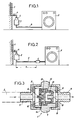
- FIG. 1 of the appended drawing where the reference 1 designates the water supply network, to which an electrical household appliance 2 must be connected. 3, or an electromagnetic safety valve, is directly connected to the water inlet 4 of the network 1.
- the valve 3 is also connected, by means of a flexible supply pipe 5 of a certain length, to the household appliance 2.
- This valve 3 is equipped with a flow regulator 6, making it possible to fix a flow necessary for the operation of the appliance 2.
- the passage of water in the flow regulator 6 induces a cavitation phenomenon within it.
- the cavitation noise is amplified by the supply conduits of the network 1 and it propagates along these.
- the stopping of the liquid in the rigid pipe causes a shock wave, and the noise of the shock wave also propagates along the pipes.
- the present invention aims to eliminate, or at least to greatly reduce the above drawbacks, by a different overall arrangement of the supply device.
- the subject of the invention is a liquid supply device, with noise and water hammer reducer, intended to connect a liquid user device to a liquid supply network, the device being of the type comprising an electromagnetic valve or an electromagnetic safety valve, connected to a mains water supply, the valve being connected by means of a flexible supply pipe to the device, and also comprising a flow regulator, these measures being characterized in that the flow regulator is arranged downstream of the electromagnetic valve, at a distance from this valve, with the interposition of a length of flexible supply pipe.
- the noises generated by the cavitation phenomena in this regulator and the intensity of the blows ram can be greatly diminished.
- the position adopted by the invention for the flow regulator removes the seat from cavitation phenomena; the noises generated by these are absorbed by the flexible supply pipe and they therefore no longer propagate along the pipes of the water supply network.
- the intensity of the water hammer, appearing when the electromagnetic valve closes, is also reduced, for similar reasons: when the valve closes, the shock wave causes a slight expansion of the supply pipe flexible, and the increase in volume of said pipe makes it possible to dissipate part of the energy due to the shock wave, hence a reduction in its intensity.
- the flow regulator installed downstream of the electromagnetic valve, mainly performs the function of regulating the flow necessary for the operation of the household appliance, according to a known principle.
- This flow regulator may include, in addition to the members forming the flow regulator proper, a nozzle defining an expansion chamber and making it possible to reduce noise.
- the flow regulator may in particular be installed at the inlet. from the laundry box of the household appliance, or be integrated into the laundry box of this household appliance.
- the subject of the invention is also, as such, an electrical household appliance such as a dishwasher or washing machine, comprising a water supply device with noise and water hammer reducer as defined above. above.
- Figure 2 is an overall view, very schematic, of a device according to the present invention, applied to the water supply of a household appliance;
- Figure 3 is a sectional view showing the detail of the flow regulator belonging to the device of Figure 2.
- Figure 2 is a block diagram of the device according to the invention, using the same reference numerals as Figure 1 and thus allowing an easy comparison of the invention with the prior art.
- the device always includes an electromagnetic valve 3, or an electromagnetic safety valve, directly connected to a water inlet 4 of a supply network 1, and connected via a flexible supply pipe 5 to a household appliance 2, such as a dishwasher or washing machine.
- a flow regulator 6 is disposed downstream of the electromagnetic valve 3, towards the end of the flexible supply pipe 5 and near the household appliance 2.
- the length L of pipe flexible supply 5 present between the valve 3 and the flow regulator 6 ensures the damping of the noises generated by the cavitation phenomena, themselves induced by the passage of water in the flow regulator 6.
- the flexible supply pipe 5 partially absorbs the shock wave emitted when the electromagnetic valve 3 is closed, thereby reducing the intensity of the pressure surges.
- FIG. 3 shows the structure of the flow regulator 6 belonging to the device according to the invention, in a particular embodiment.
- the flow regulator 6 comprises an annular central body 7, a first end piece 8 provided with a nozzle 9 for water inlet connected to the end of the flexible supply pipe 5 remote from the valve 3, and a second end piece 10 provided with a nozzle 11 for water outlet, connected to the inlet of the household appliance.
- the actual flow regulator comprises a circular piece 12, for example of plastic, pierced with openings 13 for the passage of water.
- the face of the circular part 12 facing upstream is provided with small studs 14, arranged in a circle, on which rests a rubber or similar lining 15, in the form of a washer, retained on a central lug 16 of the part. circular 12.
- the flow rate is established by the passage sections between the pins 14 and the rubber lining 15, whose position is variable depending on the water pressure.
- the flow rate increases until the lining 15, being crushed on the pins 14, reduces the passage sections.
- the variation of these sections as a function of the pressure makes it possible to obtain flow regulation.
- the flow regulator 6 further comprises a nozzle 17, disposed inside the central body 7 downstream from the circular part 12 of the flow regulator proper.
- the nozzle 17 essentially consists of a part with symmetry of revolution, for example made of plastic, having a central hole 18 calibrated as a function of the desired flow rate.
- the nozzle 17 also delimits, around its central hole 18, an annular expansion chamber 19. The role of the expansion chamber 19 is to drop the pressure and the speed of the water, therefore to reduce noise, its operation can be compared to that of an exhaust.
Landscapes
- Engineering & Computer Science (AREA)
- General Engineering & Computer Science (AREA)
- Textile Engineering (AREA)
- Mechanical Engineering (AREA)
- Water Supply & Treatment (AREA)
- Detail Structures Of Washing Machines And Dryers (AREA)
- Main Body Construction Of Washing Machines And Laundry Dryers (AREA)
- Control Of Washing Machine And Dryer (AREA)
- Washing And Drying Of Tableware (AREA)
- Cleaning And Drying Hair (AREA)
Claims (8)
- Vorrichtung zur Flüssigkeitsversorgung mit einer Einrichtung zum Dämpfen des Schalls und von Flüssigkeitsschlägen, vorgesehen zum Anschluß eines Flüssigkeitsverbrauchers (2) an eine Flüssigkeitsquelle (1), wobei die Vorrichtung ein Elektromagnetventil (3) oder ein elektromagnetisches Sicherheitsventil aufweist, das an eine Wasserleitung (4) der Quelle (1) angeschlossen ist, und wobei das Ventil (3) über einen Schlauch oder über ein biegsames Rohr (5) an den Verbraucher (2) angeschlossen ist und eine Einstellvorrichtung für die abzugebene Menge aufweist,
dadurch gekennzeichnet,
daß die Einstellvorrichtung (6) stromab des Elektromagnetventils (3) angeordnet ist, und zwar beabstandet vom Ventil unter Einfügung einer bestimmten Länge (L) des Schlauchs bzw. des biegsamen Rohrs (5). - Vorrichtung nach Anspruch 1,
dadurch gekennzeichnet,
daß die Einstellvorrichtung (6) an dasjenige Ende des Schlauchs oder Rohres (5) angeschlossen ist, das vom Ventil (3) entfernt angeordnet ist. - Vorrichtung nach Anspruch 1,
dadurch gekennzeichnet,
daß die Einstellvorrichtung (6) sich direkt im Inneren des Schlauches oder Rohres (5) befindet. - Vorrichtung nach einem der Patentansprüche 1 - 3,
dadurch gekennzeichnet,
daß die Einstellvorrichtung (6) zusätzlich zu denjenigen Bauteilen (12 - 16), die der eigentlichen Einstellung dienen, eine Düse (17) aufweist, die eine Entspannungskammer (19) begrenzt. - Vorrichtung nach einem der Patentansprüche 1 - 4,
dadurch gekennzeichnet,
daß der Flüssigkeitsverbraucher ein elektrisches Haushaltsgerät (2) ist, beispielsweise ein Geschirrspüler oder eine Waschmaschine. - Vorrichtung nach Anspruch 5,
dadurch gekennzeichnet,
daß die Einstellvorrichtung (6) am Eingang der Waschkammer des elektrischen Haushaltsgeräts (2) angeordnet ist. - Vorrichtung nach Anspruch 5,
dadurch gekennzeichnet,
daß die Einstellvorrichtung (6) in die Waschkammer des elektrischen Haushaltsgeräts (2) integriert ist. - Elektrisches Haushaltsgerät (2), beispielsweise Geschirrspüler oder Waschmaschine, versehen mit einer Wasserversorgung mit einer Einrichtung zum Dämpfen des Schalls und von Flüssigkeitsschlägen nach einem der Patentansprüche 1 - 7.
Applications Claiming Priority (2)
| Application Number | Priority Date | Filing Date | Title |
|---|---|---|---|
| FR9104392 | 1991-04-05 | ||
| FR9104392A FR2674936B1 (fr) | 1991-04-05 | 1991-04-05 | Dispositif d'alimentation en liquide, avec reducteur de bruits et de coups de belier. |
Publications (2)
| Publication Number | Publication Date |
|---|---|
| EP0507705A1 EP0507705A1 (de) | 1992-10-07 |
| EP0507705B1 true EP0507705B1 (de) | 1994-09-28 |
Family
ID=9411696
Family Applications (1)
| Application Number | Title | Priority Date | Filing Date |
|---|---|---|---|
| EP92420101A Expired - Lifetime EP0507705B1 (de) | 1991-04-05 | 1992-04-01 | Zuleitungsvorrichtung von Flüssigkeiten mit einem Geräusch- und Wasserschlagdämpfer |
Country Status (4)
| Country | Link |
|---|---|
| EP (1) | EP0507705B1 (de) |
| DE (1) | DE69200455T2 (de) |
| ES (1) | ES2065148T3 (de) |
| FR (1) | FR2674936B1 (de) |
Families Citing this family (2)
| Publication number | Priority date | Publication date | Assignee | Title |
|---|---|---|---|---|
| EP3588042B1 (de) | 2018-06-22 | 2021-03-31 | Siemens Aktiengesellschaft | Druckelement |
| DE102022200869A1 (de) | 2022-01-26 | 2023-07-27 | Siemens Aktiengesellschaft | Vorrichtung und Verfahren zur Detektion von Änderungen eines Wertes einer physikalischen Größe |
Family Cites Families (3)
| Publication number | Priority date | Publication date | Assignee | Title |
|---|---|---|---|---|
| FR806053A (fr) * | 1935-04-25 | 1936-12-07 | A Senee & Fils S A R L Ets | Détendeur hydraulique anti-bélier |
| US2389887A (en) * | 1944-01-31 | 1945-11-27 | Baxter Benjamin | Valve unit |
| DE3917016A1 (de) * | 1989-05-24 | 1990-11-29 | Bosch Siemens Hausgeraete | Sicherheitsschlauch zum anschliessen einer wasserfuehrenden haushaltmaschine |
-
1991
- 1991-04-05 FR FR9104392A patent/FR2674936B1/fr not_active Expired - Fee Related
-
1992
- 1992-04-01 EP EP92420101A patent/EP0507705B1/de not_active Expired - Lifetime
- 1992-04-01 DE DE69200455T patent/DE69200455T2/de not_active Expired - Fee Related
- 1992-04-01 ES ES92420101T patent/ES2065148T3/es not_active Expired - Lifetime
Also Published As
| Publication number | Publication date |
|---|---|
| FR2674936A1 (fr) | 1992-10-09 |
| EP0507705A1 (de) | 1992-10-07 |
| DE69200455T2 (de) | 1995-05-11 |
| DE69200455D1 (de) | 1994-11-03 |
| ES2065148T3 (es) | 1995-02-01 |
| FR2674936B1 (fr) | 1993-11-12 |
Similar Documents
| Publication | Publication Date | Title |
|---|---|---|
| EP0540800B1 (de) | Handstück mit Düse zur Körperpflege | |
| WO2010029085A1 (fr) | Dispositif de commande de l'alimentation d'un systeme avec un fluide. | |
| FR2560662A1 (fr) | Valve d'expansion thermostatique munie d'un dispositif d'amortissement des vibrations | |
| EP0330575B1 (de) | Hydraulischer Kreislauf mit zugehörigem Sicherheitsventil für hydraulische Verbraucher | |
| FR2567392A1 (fr) | Dispositif de securite contre les inondations, pour appareils menagers utilisateurs d'eau | |
| FR2599804A1 (fr) | Robinet de bouteille de gaz ou similaire | |
| EP0507705A1 (de) | Zuleitungsvorrichtung von Flüssigkeiten mit einem Geräusch- und Wasserschlagdämpfer | |
| FR2727734A1 (fr) | Vannes de reglage a double debit | |
| FR2503831A1 (fr) | Dispositif de securite pour appareils menagers fonctionnant a l'eau, en particulier pour lave-vaisselle et machines a laver | |
| FR3074541B1 (fr) | Accumulateur integre a une canalisation de carburant | |
| FR2519272A1 (fr) | Buse melangeuse reglable d'air et d'eau | |
| FR2969734A1 (fr) | Dispositif de commande du debit d’un fluide de refroidissement | |
| FR2745058A1 (fr) | Electrovanne de regulation pour circuit de fluide, notamment gazeux | |
| US3055392A (en) | Faucet attachment for dishwashers and the like | |
| FR2853963A1 (fr) | Dispositif de detection de fuites de faibles debits | |
| US3818931A (en) | Water hammer arrester | |
| FR2682164A1 (fr) | Installation de pompage de gaz avec regulation de la vitesse de pompage. | |
| FR2472709A1 (fr) | Robinet commande par bouton-poussoir | |
| FR2659412A1 (fr) | Dispositif de clapet anti-retour pour circuits hydrauliques. | |
| BE1022592B1 (fr) | Robinet d'arret et de reglage de debit | |
| EP3981314B1 (de) | Überlaufschutz-abschaltsystem | |
| EP0882967B1 (de) | Apparatur zur Anzeige einer Strömung, insbesondere verursacht durch ein Leck in einem Flüssigkeitskreislauf | |
| FR2611023A1 (fr) | Appareil anti-coups de belier a membrane | |
| FR2716705A1 (fr) | Soupape de commande de la circulation d'un fluide dans un conduit. | |
| CA2172300C (fr) | Dispositif de securite contre l'inondation du a l'alimentation en eau par un tuyau flexible d'un appareil de lavage |
Legal Events
| Date | Code | Title | Description |
|---|---|---|---|
| PUAI | Public reference made under article 153(3) epc to a published international application that has entered the european phase |
Free format text: ORIGINAL CODE: 0009012 |
|
| AK | Designated contracting states |
Kind code of ref document: A1 Designated state(s): DE ES FR GB IT |
|
| 17P | Request for examination filed |
Effective date: 19921024 |
|
| 17Q | First examination report despatched |
Effective date: 19940301 |
|
| GRAA | (expected) grant |
Free format text: ORIGINAL CODE: 0009210 |
|
| AK | Designated contracting states |
Kind code of ref document: B1 Designated state(s): DE ES FR GB IT |
|
| REF | Corresponds to: |
Ref document number: 69200455 Country of ref document: DE Date of ref document: 19941103 |
|
| ITF | It: translation for a ep patent filed | ||
| REG | Reference to a national code |
Ref country code: ES Ref legal event code: FG2A Ref document number: 2065148 Country of ref document: ES Kind code of ref document: T3 |
|
| GBT | Gb: translation of ep patent filed (gb section 77(6)(a)/1977) |
Effective date: 19950113 |
|
| PLBE | No opposition filed within time limit |
Free format text: ORIGINAL CODE: 0009261 |
|
| 26N | No opposition filed | ||
| PGFP | Annual fee paid to national office [announced via postgrant information from national office to epo] |
Ref country code: FR Payment date: 19990226 Year of fee payment: 8 |
|
| PGFP | Annual fee paid to national office [announced via postgrant information from national office to epo] |
Ref country code: GB Payment date: 20000317 Year of fee payment: 9 |
|
| PGFP | Annual fee paid to national office [announced via postgrant information from national office to epo] |
Ref country code: ES Payment date: 20000411 Year of fee payment: 9 |
|
| PGFP | Annual fee paid to national office [announced via postgrant information from national office to epo] |
Ref country code: DE Payment date: 20000427 Year of fee payment: 9 |
|
| PG25 | Lapsed in a contracting state [announced via postgrant information from national office to epo] |
Ref country code: FR Free format text: LAPSE BECAUSE OF NON-PAYMENT OF DUE FEES Effective date: 20001229 |
|
| REG | Reference to a national code |
Ref country code: FR Ref legal event code: ST |
|
| PG25 | Lapsed in a contracting state [announced via postgrant information from national office to epo] |
Ref country code: GB Free format text: LAPSE BECAUSE OF NON-PAYMENT OF DUE FEES Effective date: 20010401 |
|
| PG25 | Lapsed in a contracting state [announced via postgrant information from national office to epo] |
Ref country code: ES Free format text: LAPSE BECAUSE OF NON-PAYMENT OF DUE FEES Effective date: 20010402 |
|
| GBPC | Gb: european patent ceased through non-payment of renewal fee |
Effective date: 20010401 |
|
| PG25 | Lapsed in a contracting state [announced via postgrant information from national office to epo] |
Ref country code: DE Free format text: LAPSE BECAUSE OF NON-PAYMENT OF DUE FEES Effective date: 20020201 |
|
| REG | Reference to a national code |
Ref country code: ES Ref legal event code: FD2A Effective date: 20030303 |
|
| PG25 | Lapsed in a contracting state [announced via postgrant information from national office to epo] |
Ref country code: IT Free format text: LAPSE BECAUSE OF NON-PAYMENT OF DUE FEES;WARNING: LAPSES OF ITALIAN PATENTS WITH EFFECTIVE DATE BEFORE 2007 MAY HAVE OCCURRED AT ANY TIME BEFORE 2007. THE CORRECT EFFECTIVE DATE MAY BE DIFFERENT FROM THE ONE RECORDED. Effective date: 20050401 |