EP0507584A2 - Verfahren und Vorrichtung zur Entfernung von Blasen aus einer Flüssigkeit - Google Patents
Verfahren und Vorrichtung zur Entfernung von Blasen aus einer Flüssigkeit Download PDFInfo
- Publication number
- EP0507584A2 EP0507584A2 EP92302906A EP92302906A EP0507584A2 EP 0507584 A2 EP0507584 A2 EP 0507584A2 EP 92302906 A EP92302906 A EP 92302906A EP 92302906 A EP92302906 A EP 92302906A EP 0507584 A2 EP0507584 A2 EP 0507584A2
- Authority
- EP
- European Patent Office
- Prior art keywords
- flow passage
- liquid
- flow
- bubbles
- pressure
- Prior art date
- Legal status (The legal status is an assumption and is not a legal conclusion. Google has not performed a legal analysis and makes no representation as to the accuracy of the status listed.)
- Ceased
Links
- 239000007788 liquid Substances 0.000 title claims abstract description 63
- 238000000034 method Methods 0.000 title claims description 11
- 230000001133 acceleration Effects 0.000 claims description 3
- 238000007599 discharging Methods 0.000 claims 1
- 230000007423 decrease Effects 0.000 abstract description 9
- 239000012530 fluid Substances 0.000 description 8
- 230000033001 locomotion Effects 0.000 description 6
- 230000008030 elimination Effects 0.000 description 5
- 238000003379 elimination reaction Methods 0.000 description 5
- 239000003921 oil Substances 0.000 description 2
- 238000011144 upstream manufacturing Methods 0.000 description 2
- 230000015556 catabolic process Effects 0.000 description 1
- 239000011248 coating agent Substances 0.000 description 1
- 238000000576 coating method Methods 0.000 description 1
- 239000012141 concentrate Substances 0.000 description 1
- 238000006731 degradation reaction Methods 0.000 description 1
- 238000010586 diagram Methods 0.000 description 1
- 230000003292 diminished effect Effects 0.000 description 1
- 238000002474 experimental method Methods 0.000 description 1
- 239000010720 hydraulic oil Substances 0.000 description 1
- 238000005461 lubrication Methods 0.000 description 1
- 238000005259 measurement Methods 0.000 description 1
- 239000003973 paint Substances 0.000 description 1
- 239000000126 substance Substances 0.000 description 1
Images


Classifications
-
- B—PERFORMING OPERATIONS; TRANSPORTING
- B01—PHYSICAL OR CHEMICAL PROCESSES OR APPARATUS IN GENERAL
- B01D—SEPARATION
- B01D19/00—Degasification of liquids
- B01D19/0042—Degasification of liquids modifying the liquid flow
- B01D19/0052—Degasification of liquids modifying the liquid flow in rotating vessels, vessels containing movable parts or in which centrifugal movement is caused
- B01D19/0057—Degasification of liquids modifying the liquid flow in rotating vessels, vessels containing movable parts or in which centrifugal movement is caused the centrifugal movement being caused by a vortex, e.g. using a cyclone, or by a tangential inlet
Definitions
- the present invention relates to a method and a device for removing bubbles in a liquid such as fluid used in hydraulic systems, lubrication oils coating solutions in paper-making machines, paints, chemical solutions such as ink, liquid foodstuffs, and so forth.
- Applicable industrial field bubbles in a liquid of the kind described must be removed therefrom because they cause degradation of the fluids, poor product quality, increased compressivity, vibration of equipment and annoying noise.
- a bubble removing method has been made known in which the liquid is introduced into a cylindrical body tangentially and bubbles dispersed in the liquid are collected at the swirl center by means of a centrifugal force which makes the bubbles collect where the wall side pressure is higher compared with the center of swirl flow so that they can be removed easily (Japanese patent No. 1371889).
- FIGs. 4 and 5 an example of a device for practicing such a method is shown.
- Inlet port 23 is connected with a pump 28 through supply line 24.
- the other end of the cylindrical body 21 is closed by lid 26 where an outlet port 27 is open and is connected with a fluid discharge line 25.
- the liquid is introduced into the cylindrical body 21 tangentially by the pump 28 with some inflow velocity, and forms a swirl flow inside the body with centrifugal force acting upon the liquid. Consequently, the pressure at the center of the swirl becomes lower in comparison with that of the inner wall region of the body. and so bubbles concentrate towards the swirl center.
- the pressure at the center of the swirl flow is lowest in the vicinity of the inlet port 23 and increases as the liquid flows downstream;then pressure reaches maximal value and thereafter drops, and a gas column 30 is formed as indicated by lines at the center of the swirl in the vicinity of inlet port 23.
- the pressure of the center of the cylindrical body in the vicinity of the inlet port 23 is lowered into negative pressure in general, if no pressure restriction is interposed in the downstream line of the cylindrical body, resulting in suction of air from the vent line 32 installed at the center of lid 22 located at the upward end of the cylindrical body 21.
- a resistance means 29interposed in the discharge line 25 is controlled so that the above-mentioned pressure of the center of the cylindrical body in the vicinity of inlet port 23 becomes higher than the atmospheric pressure plus liquid head.
- the resistance means is provided to produce comeback pressure, and vent valve 31 of vent line 32is opened a little, and the collected bubbles are discharged through the vent line to the outside, and thus bubbles in fluid are eliminated.
- the prior art method of eliminating bubbles from liquid was by means of basically circulating the liquid in the cylindrical body and obtaining pressure gradient axially and radially in it, collecting the bubbles at the center axis of inlet port said, aid then releasing the collected bubbles.
- flow rate decreases, then circulation velocity and pressure gradient of radial direction decrease, and when the radial direction pressure gradient cannot be created, the function of collecting bubbles in the cylindrical body disappears.
- the purpose of the present invention consists in offering the device and method to eliminate bubbles effectively from the liquid of small flow rate, solving the problems encountered in the prior art.
- the present invention proposes a device for removing bubbles from liquid comprising a flow passage of circular cross section having at least one inlet port at one end and an outlet port at the other end; the inlet port causing the liquid to flow tangentially into the inner wall of said flow passage of circular cross section; said flow passage being circumferentially a gas vent hole coaxially being opened at the end of said flow passage in the vicinity of said inlet port, or end of a small vent pipe coaxially inserted in the flow passage being opened at the vicinity of the portion where diameter of flow passage is minimum; and furthermore and a method proposes a device for removing bubbles from liquid which causes liquid to flow tangentially from inlet port to said flow passage to form a swirl flow, said liquid circulate through the flow passage directing outlet port, the swirl flow accelerate at first and then decelerates it, collects bubbles at the vicinity of the portion where the acceleration of liquid turns to deceleration, and removes said coalesced mass of bubbles from the vent hole
- the pressure of the swirl center of the liquid flowing trough the flow passage of the present invention decreases as the swirl flow accelerates from the tangential inlet communicated for the first flow passage towards downstream, and increases further more in the following second flow passage towards downstream, bubbles move to the vicinity of the small diameter end of the first passage and are discharged from the vent hole or the end of the small pipe opened at the center of this area.
- back pressure means are inserted, and by means of making the pressure of swirl center of the portion of minimum pressure higher enough to overcome atmospheric pressure plus pressure loss of small vent pipe, bubbles collected at the portion of minimum pressure are discharged.
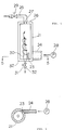
- a pipe 1 to suck the liquid is connected to a pump 2 in series, and the delivery side of the pump is connected to a supply port 10 of a bubble collector 3.
- a pressure gauge 5 is pro.vided to a supply line 4 located between pump 2 and bubble collector 3.
- the bubble collector 3 consists of a cylindrical body of outer wall having flow passage comprising the first passage 6, the second passage 7, and a block 9 enveloping the adjacent area of the upward end of the first passage 6 of the cylindrical body.
- the block 9 is provided with the supply port 10 and an annular passage 11 which are connected to one another, and the outer wall of a cylindrical body 8 adjacent to the inlet side end is surrounded by an annular passage 11 so that the liquid flows tangentially into the first passage 6 of the cylindrical body 8 from the outer space of the inlet side end.
- Inlet port 12 is formed through the first flow passage of the cylindrical body 8 at the upward end so that the first flow passage 6 is connected tangentially to annular passage 11.
- the cylindrical body 8 has a first flow passage 6 of conical shape whose diameter becomes gradually and continuously smaller towards the downstream side and the second flow passage 7, and is connected with the second flow passage at junction 13 having either a reverse conical shape whose diameter becomes larger gradually and continuously or a cylindrical shape with a diameter at least the size of the junction.
- the flow passage 7 is so designed that as the liquid flows downstream, a centrifugal force acting on the swirl flow becomes smaller and the pressure of the swirl increases.
- a vent hole 15 is formed through block 9 surrounding the upstream end of the cylindrical body 8 along its axis.
- a discharge line 17 is connected to the downstream end of the secondary flow passage 7 of cylindrical body 8 and resistance means 18, such as a throttle valve to provide back pressure, is incorporated in the line 17.
- resistance means 18 such as a throttle valve to provide back pressure, is incorporated in the line 17.
- a pressure means an orifice, a check valve or a pipe of small sectional area can be used for some cases.
- vent pipe 19 is inserted along the center of the first flow passage 6 to junction 13 which connects it to the secondary flow passage. Collected bubble mass at the end port-of-vent pipe is illustrated as reference No. 20.
- Liquid containing bubbles is sucked by pump 2 through suction pipe 1 and is delivered through supply line 4 to bubble collector 3; it then passes through supply port 10 and annular passage 11 to inlet port 12, streams tangentially to the first flow passage 6 of cylindrical body 8, and moves downstream in the first flow passage 6 as a swirl flow.
- resistance means 18, such as throttle valve 18, beforehand it is necessary to open resistance means 18, such as throttle valve 18, beforehand.Since the diameter of the first flow passage becomes gradually and continuously smaller towards downstream, an angular velocity of swirled liquid in the flow passage increases toward downstream and centrifugal force increases.
- Centrifugal force acts on the swirl flow, so then the pressure at the center of the swirl is lower in comparison with that of the inner wall region of the cylindrical body.
- Change of diameter of the first flow passage is decided by the conditions of liquid so that the pressure at the swirl center decreases from inlet port side to downstream.
- the liquid swirls downstream through junction 13, where the diameter is the smallest in the flow passage, and through the second flow passage which is either cylindrical or conical and whose diameter becomes larger moving downstream so that the swirl motion continues. Since the centrifugal force decreases in the secondary flow passage 7 as the liquid flows downstream, the pressure of the swirl center increases as the liquid flows downstream and finally reaches the end of cylindrical body 8. Namely, pressure of the swirl center of fluid in the cylindrical body 8 becomes lowest at the junction of the first and second flow passages.
- Bubbles in the fluid are fed to the first flow passage 6 and swirled within the fluid in the passage and then moved to the center of the swirl by means of buoyancy caused by a radial directional pressure difference.produced by centrifugal force.
- the bubbles gather into the collected bubble mass 20 at the first and secondary flow passages where the pressure is lowest, and then are collected.
- vent valve 14 of vent line 16 is opened in order to discharge collected bubbles through small vent line 16, and the liquid from which bubbles are eliminated flows from discharge line 17.
- the throttle valve for the resistance means 18 can be replaced by another back pressure means whose pressure cannot be controlled, such as an orifice, check valve, or pipe of small cross sectional diameter, etc..
- Fig. 3 shows the second embodiment of the invention.
- each components working the same as those of the first embodiment provides with the same reference numeral. However this embodiment is so different from the first embodiment that:
- the inlet ports 12′ of a body 8′ having an cylindrical outer surface of the bubble collector 3′ are directed to the central axis at an angle ⁇ in the direction of axial flow.
- ⁇ is given as following formula: where: L may be calculated as L ⁇ r
- the second flow passage 7′ is provided with a diameter same or larger that the smallest diameter of the first flow passage.
- This configuration of the second passage makes a central pressure of the swirl flow increasing in the direction of outlet.
- the working of the second embodiment is described as follows; The working of the second embodiment form inlet to outlet of the liquid involving bubbles is the same as that of the first embodiment. However the liquid introduced from the inlet port of the first flow passage (b) encounters with liquid flowing in from the port (6) so that the swirl action of the flow can is reduced. Therefore in case of processing a little amount of liquid, bubble can not be removed from the liquid, even if there be the small diameter of the flow passage in accordance with the small amount of liquid.
- the concept according to the second embodiment prevents a mutual contact of a swill flows by means of an inlet port directed to the central axis at an angle ⁇ in the direction of axial flow. Therefore the center pressure of swirl flow is the lowest in the vicinity of joining point (13'), and the swirl flow in the second flow passage is reduced owing to the viscosity of the liquid, so that it increases in the direction of the outlet port.
- the second flow passage may be provided with a cylindrical inner surface.
- the diameter of the flow passage decreases and centrifugal force increases. Therefore, the pressure along the center axis decreases, and bubbles are collected at the portion where the pressure becomes minimum. Thus collected bubbles are discharged from the vent pipe whose port is opened around the area of minimum pressure.
Landscapes
- Chemical & Material Sciences (AREA)
- Chemical Kinetics & Catalysis (AREA)
- Degasification And Air Bubble Elimination (AREA)
Priority Applications (1)
| Application Number | Priority Date | Filing Date | Title |
|---|---|---|---|
| EP96200005A EP0715871A2 (de) | 1991-04-03 | 1992-04-02 | Verfahren und Vorrichtung zur Entfernung von Blasen aus einer Flüssigkeit |
Applications Claiming Priority (4)
| Application Number | Priority Date | Filing Date | Title |
|---|---|---|---|
| JP7111891 | 1991-04-03 | ||
| JP71118/91 | 1991-04-03 | ||
| JP64792/92 | 1992-03-23 | ||
| JP06479292A JP3261506B2 (ja) | 1991-04-03 | 1992-03-23 | 液体中の気泡除去装置 |
Related Child Applications (1)
| Application Number | Title | Priority Date | Filing Date |
|---|---|---|---|
| EP96200005.5 Division-Into | 1992-04-02 |
Publications (2)
| Publication Number | Publication Date |
|---|---|
| EP0507584A2 true EP0507584A2 (de) | 1992-10-07 |
| EP0507584A3 EP0507584A3 (en) | 1993-03-03 |
Family
ID=26405895
Family Applications (2)
| Application Number | Title | Priority Date | Filing Date |
|---|---|---|---|
| EP96200005A Withdrawn EP0715871A2 (de) | 1991-04-03 | 1992-04-02 | Verfahren und Vorrichtung zur Entfernung von Blasen aus einer Flüssigkeit |
| EP19920302906 Ceased EP0507584A3 (en) | 1991-04-03 | 1992-04-02 | Method and device for removing bubbles from liquid |
Family Applications Before (1)
| Application Number | Title | Priority Date | Filing Date |
|---|---|---|---|
| EP96200005A Withdrawn EP0715871A2 (de) | 1991-04-03 | 1992-04-02 | Verfahren und Vorrichtung zur Entfernung von Blasen aus einer Flüssigkeit |
Country Status (3)
| Country | Link |
|---|---|
| US (1) | US5240477A (de) |
| EP (2) | EP0715871A2 (de) |
| JP (1) | JP3261506B2 (de) |
Cited By (6)
| Publication number | Priority date | Publication date | Assignee | Title |
|---|---|---|---|---|
| EP0688597A1 (de) * | 1994-06-20 | 1995-12-27 | Rockwell International Corporation | Trennung chemischer Spezies aus einem Gemisch durch Wirbelstromtrennung |
| DE4427013A1 (de) * | 1994-07-29 | 1996-02-01 | Loctite Europa Eeig | Verfahren und Vorrichtung zum Entfernen von Gasblasen aus einer auszugebenden viskosen Flüssigkeit |
| US5510019A (en) * | 1993-07-30 | 1996-04-23 | Mitsubishi Oil Co., Ltd. | Bubble separating apparatus |
| EP2992260A4 (de) * | 2013-04-29 | 2016-12-28 | Typhonix As | Fluss- und flüssigkeitskonditionierendes druckminderungsventil oder vorrichtung |
| CN112892001A (zh) * | 2021-01-13 | 2021-06-04 | 青岛理工大学 | 微气泡轴流和旋流双场三级管式t型脱气装置 |
| CN119793012A (zh) * | 2025-03-13 | 2025-04-11 | 浙江西子联合工程有限公司 | 液位变送器防气泡干扰装置 |
Families Citing this family (13)
| Publication number | Priority date | Publication date | Assignee | Title |
|---|---|---|---|---|
| JP2766604B2 (ja) * | 1993-07-30 | 1998-06-18 | 三菱石油株式会社 | 気泡分離装置 |
| US5514206A (en) * | 1994-04-15 | 1996-05-07 | Consolidated Papers, Inc. | Air/gas separator device |
| CN1089871C (zh) * | 1997-04-07 | 2002-08-28 | 芦森工业株式会社 | 齿形皮带 |
| JP4677933B2 (ja) * | 2005-04-14 | 2011-04-27 | セイコーエプソン株式会社 | ポンプ及び流体システム |
| US7571750B2 (en) * | 2005-08-23 | 2009-08-11 | General Electric Co. | Tool for transferring controlled amounts of fluid into and from a fluid flow circuit |
| NO334212B1 (no) * | 2005-08-23 | 2014-01-13 | Typhonix As | Anordning ved reguleringsventil |
| GB0801471D0 (en) | 2008-01-25 | 2008-03-05 | Typhonix As | Valve |
| DE102008029203A1 (de) | 2008-06-19 | 2009-12-24 | Rt-Filtertechnik Gmbh | Vorrichtung zur Medientrennung |
| CN101787993B (zh) * | 2010-01-26 | 2012-07-11 | 云南省机械研究设计院 | 提高液压系统液压传动刚度的方法 |
| KR101719607B1 (ko) * | 2015-08-26 | 2017-03-24 | 주식회사 케이티앤지 | 기포 제거 장치 및 기포 제거 방법 |
| US10709206B2 (en) | 2015-11-30 | 2020-07-14 | Nike, Inc. | Method of filling electrorheological fluid structure |
| WO2019046515A1 (en) | 2017-08-31 | 2019-03-07 | Nike Innovate C.V. | DEGASTING ELECTRO-HEAT FLUID |
| CN112941546B (zh) * | 2021-01-26 | 2022-09-27 | 深圳市橘井舒泉技术有限公司 | 臭氧水制造机 |
Citations (1)
| Publication number | Priority date | Publication date | Assignee | Title |
|---|---|---|---|---|
| JPS5836606A (ja) | 1981-08-26 | 1983-03-03 | Ishikawajima Harima Heavy Ind Co Ltd | 流体中の気泡集合方法 |
Family Cites Families (6)
| Publication number | Priority date | Publication date | Assignee | Title |
|---|---|---|---|---|
| NL113099C (de) * | ||||
| US3007542A (en) * | 1957-06-18 | 1961-11-07 | Salvatore W Giampapa | Degasifier |
| US3501014A (en) * | 1968-06-13 | 1970-03-17 | Univ Oklahoma State | Regenerative hydrocyclone |
| US4670410A (en) * | 1981-06-22 | 1987-06-02 | Atlantic Richfield Company | Method for reducing attrition of particulate matter in a chemical conversion process |
| JPS59190307U (ja) * | 1983-06-01 | 1984-12-17 | 石川島播磨重工業株式会社 | 気泡除去装置 |
| JPH038323Y2 (de) * | 1984-09-11 | 1991-02-28 |
-
1992
- 1992-03-23 JP JP06479292A patent/JP3261506B2/ja not_active Expired - Fee Related
- 1992-04-02 US US07/862,119 patent/US5240477A/en not_active Expired - Lifetime
- 1992-04-02 EP EP96200005A patent/EP0715871A2/de not_active Withdrawn
- 1992-04-02 EP EP19920302906 patent/EP0507584A3/en not_active Ceased
Patent Citations (1)
| Publication number | Priority date | Publication date | Assignee | Title |
|---|---|---|---|---|
| JPS5836606A (ja) | 1981-08-26 | 1983-03-03 | Ishikawajima Harima Heavy Ind Co Ltd | 流体中の気泡集合方法 |
Non-Patent Citations (1)
| Title |
|---|
| SUZUKI, THE JOURNAL OF THE JAPAN HYDRAULICS, vol. 19, no. 6, September 1988 (1988-09-01) |
Cited By (9)
| Publication number | Priority date | Publication date | Assignee | Title |
|---|---|---|---|---|
| US5510019A (en) * | 1993-07-30 | 1996-04-23 | Mitsubishi Oil Co., Ltd. | Bubble separating apparatus |
| EP0688597A1 (de) * | 1994-06-20 | 1995-12-27 | Rockwell International Corporation | Trennung chemischer Spezies aus einem Gemisch durch Wirbelstromtrennung |
| DE4427013A1 (de) * | 1994-07-29 | 1996-02-01 | Loctite Europa Eeig | Verfahren und Vorrichtung zum Entfernen von Gasblasen aus einer auszugebenden viskosen Flüssigkeit |
| US5584416A (en) * | 1994-07-29 | 1996-12-17 | Loctite Europa Eeig | Process and device for removing gas bubbles from a viscous liquid to be dispensed |
| EP2992260A4 (de) * | 2013-04-29 | 2016-12-28 | Typhonix As | Fluss- und flüssigkeitskonditionierendes druckminderungsventil oder vorrichtung |
| US9650862B2 (en) | 2013-04-29 | 2017-05-16 | Typhonix As | Flow and fluid conditioning pressure reducing valve or device |
| US10053956B2 (en) | 2013-04-29 | 2018-08-21 | Typhonix As | Flow and fluid conditioning pressure reducing valve or device |
| CN112892001A (zh) * | 2021-01-13 | 2021-06-04 | 青岛理工大学 | 微气泡轴流和旋流双场三级管式t型脱气装置 |
| CN119793012A (zh) * | 2025-03-13 | 2025-04-11 | 浙江西子联合工程有限公司 | 液位变送器防气泡干扰装置 |
Also Published As
| Publication number | Publication date |
|---|---|
| JP3261506B2 (ja) | 2002-03-04 |
| US5240477A (en) | 1993-08-31 |
| EP0715871A2 (de) | 1996-06-12 |
| JPH0584403A (ja) | 1993-04-06 |
| EP0715871A3 (de) | 1996-06-26 |
| EP0507584A3 (en) | 1993-03-03 |
Similar Documents
| Publication | Publication Date | Title |
|---|---|---|
| EP0507584A2 (de) | Verfahren und Vorrichtung zur Entfernung von Blasen aus einer Flüssigkeit | |
| US4390351A (en) | Gas-liquid separator | |
| JP3630720B2 (ja) | 全流−バイパス複合型フィルタ | |
| EP0654292B1 (de) | Vorrichtung zum Entgasen von Flüssigkeiten | |
| US3955945A (en) | Oil separator for air compressors and the like | |
| KR930009499B1 (ko) | 이종 유체용 로타리 와동 분리기 | |
| EP0400202B1 (de) | Vorrichtung zur Entfernung von Gasen aus Flüssigkeiten | |
| JPS6136444B2 (de) | ||
| US5427685A (en) | Separator for separating gas from a liquid | |
| US5064449A (en) | Fluid degassing | |
| CA1087110A (en) | Apparatus for removing gas from a liquid system | |
| US4662908A (en) | Device for removing bubbles from liquid | |
| EP0342308B1 (de) | Integrierte Trennvorrichtung für in einem Fluid enthaltene feste und gasförmige Verunreinigungen | |
| EP0609228A4 (en) | Paper coater skip prevention and deaeration apparatus & method. | |
| US4276059A (en) | Deaerator for pulp stock | |
| US4643746A (en) | Apparatus for separating gas from fluid | |
| US5051072A (en) | Gas removable pump for liquid | |
| US4411673A (en) | Method and apparatus for degassing liquids | |
| US6783334B2 (en) | Hydraulic pump reservoir having deaeration diffuser | |
| EP0307965B1 (de) | Integriertes Entlastungsventil mit Gasabtrennvorrichtung für eine Flüssigkeit | |
| EP0423396A2 (de) | Vorrichtung zur Entfernung von Gasblasen aus einer Flüssigkeit | |
| JPH08318103A (ja) | 気泡除去システム及び方法 | |
| JPH07232004A (ja) | 流量対応型気泡分離装置 | |
| JPH0745002B2 (ja) | 液体中の気泡除去システム | |
| SU1261691A1 (ru) | Центробежный рециркул ционный сепаратор |
Legal Events
| Date | Code | Title | Description |
|---|---|---|---|
| PUAI | Public reference made under article 153(3) epc to a published international application that has entered the european phase |
Free format text: ORIGINAL CODE: 0009012 |
|
| AK | Designated contracting states |
Kind code of ref document: A2 Designated state(s): DE FR GB IT |
|
| PUAL | Search report despatched |
Free format text: ORIGINAL CODE: 0009013 |
|
| AK | Designated contracting states |
Kind code of ref document: A3 Designated state(s): DE FR GB IT |
|
| 17P | Request for examination filed |
Effective date: 19930814 |
|
| 17Q | First examination report despatched |
Effective date: 19940524 |
|
| GRAG | Despatch of communication of intention to grant |
Free format text: ORIGINAL CODE: EPIDOS AGRA |
|
| STAA | Information on the status of an ep patent application or granted ep patent |
Free format text: STATUS: THE APPLICATION HAS BEEN REFUSED |
|
| 18R | Application refused |
Effective date: 19970802 |