EP0507248A2 - Glass ceramic cooking hob in which a reflecting surface in a position corresponding with a light and/or heat generator is protected against overheating - Google Patents
Glass ceramic cooking hob in which a reflecting surface in a position corresponding with a light and/or heat generator is protected against overheating Download PDFInfo
- Publication number
- EP0507248A2 EP0507248A2 EP92105515A EP92105515A EP0507248A2 EP 0507248 A2 EP0507248 A2 EP 0507248A2 EP 92105515 A EP92105515 A EP 92105515A EP 92105515 A EP92105515 A EP 92105515A EP 0507248 A2 EP0507248 A2 EP 0507248A2
- Authority
- EP
- European Patent Office
- Prior art keywords
- generator
- light
- cooking hob
- reflecting element
- heat
- Prior art date
- Legal status (The legal status is an assumption and is not a legal conclusion. Google has not performed a legal analysis and makes no representation as to the accuracy of the status listed.)
- Granted
Links
Images
Classifications
-
- H—ELECTRICITY
- H05—ELECTRIC TECHNIQUES NOT OTHERWISE PROVIDED FOR
- H05B—ELECTRIC HEATING; ELECTRIC LIGHT SOURCES NOT OTHERWISE PROVIDED FOR; CIRCUIT ARRANGEMENTS FOR ELECTRIC LIGHT SOURCES, IN GENERAL
- H05B3/00—Ohmic-resistance heating
- H05B3/68—Heating arrangements specially adapted for cooking plates or analogous hot-plates
- H05B3/74—Non-metallic plates, e.g. vitroceramic, ceramic or glassceramic hobs, also including power or control circuits
- H05B3/744—Lamps as heat source, i.e. heating elements with protective gas envelope, e.g. halogen lamps
-
- F—MECHANICAL ENGINEERING; LIGHTING; HEATING; WEAPONS; BLASTING
- F24—HEATING; RANGES; VENTILATING
- F24C—DOMESTIC STOVES OR RANGES ; DETAILS OF DOMESTIC STOVES OR RANGES, OF GENERAL APPLICATION
- F24C15/00—Details
- F24C15/22—Reflectors for radiation heaters
Definitions
- This utility model relates to a glass ceramic cooking hob of the type comprising a surface on which containers containing food to be prepared are placed, below said surface there being provided at least one light and/or heat generator, such as a halogen lamp or the like, at which there is positioned an element reflecting the light and/or heat and having at least one face facing the generator or halogen lamp and an opposing face facing an external environment, said surface and said reflecting element defining a chamber in which said generator is located.
- a light and/or heat generator such as a halogen lamp or the like
- the reflecting element is generally formed of aluminium because this material has considerable reflecting properties. This element allows optimum direction of the lamp-generated light rays towards the cooking hob, on the surface of which said container is placed, so increasing the heat transmitted to this latter.
- the quantity of heat energy which can be fed to said container is limited by the reflecting element itself, which is generally the thermally weakest member of the glass ceramic cooking hob.
- This element heats up both because of the energy (eg. light energy) which reaches it and also because of conduction between the air present in the chamber containing the generator and the element itself.
- energy eg. light energy
- An object of the present utility model is to provide a cooking hob in which the reflecting element is thermally protected so as to prevent it overheating, or generally to prevent it reaching a temperature which could induce mechanical damage.
- a further object is to provide a reflecting element which is thermally reinforced and allows a greater transfer of energy to the container placed on the hob.
- a further object is to provide a cooking hob in which the reflecting element can be maintained at a temperature lower than that at which damage or deformation could result.
- a glass ceramic cooking hob of the aforesaid type characterised by comprising at least one body between the light and/or heat generator and the reflecting element, said body being transparent to the energy emitted by the light and/or heat generator and defining an interspace at the reflecting element, so as to insulate this latter from a part of the chamber, containing said generator, which is more sensitive to the heat generated during the operation of said generator.
- a glass ceramic cooking hob is indicated overall by 1. It comprises a surface 2 which supports with direct contact usual containers 3 (only one is shown in Figure 1) containing food 1 to be subjected to preparation.
- heating elements 5 are associated with the cooking hob 1, they being positioned below the hob.
- the elements 5 are halogen lamps 6 powered in any known manner and of suitable (known) shape to heat the cxs 3 on the hob 1 by the heat generated during their operation.
- a known screen or reflecting element 10 arranged to suitably direct the light and heat rays 11 generated by said lamps towards the upperly positioned hob 1.
- the screen 10 is constructed of aluminium and comprises a series of concavities and convexities 12 and 13 (with reference to the lamps), the concavities being positioned in correspondence with and below the lamps 6.
- the screen 10 directs the rays 11 substantially perpendicularly onto the hob 1, thus increasing the heating effect of the rays on the hob.
- the aluminium screen 10 has a face 15 facing the lamps 6 and a face 16 facing an external environment, such as a compartment 17 of a usual kitchen furniture unit 18.
- a body 20 advantageously having the same shape as the element 10 and lying parallel to it.
- the body 20 is formed of a material which is transparent to the light energy emitted by the lamps 6 but has a low capacity to conduct heat and a low refractive index, such as the usual constituent material of the glass ceramic hob.
- the body 20 divides the chamber 19 into two portions 21 and 22.
- One of these, namely the portion 21, contains the lamp with the result that the air contained in it is subject to greater heating by virtue of their operation.
- the other portion 22 is substantially insulated from the portion 21 by the body 20, the air present in it being subject to lesser heating by virtue of the operation of the lamps 6.
- the element or screen 10 is less subject to heating by conduction deriving from the contact between the screen and the (hot) air present about the lamps.
- the heating of the reflecting element is hence reduced overall, so preventing its temperature reaching a value critical or its mechanical stability.
- Any heat absorbed by the reflecting element 10 is removed from it by natural or forced convention.
- a usual fan 24 driven by its own electric motor 25 (powered in known manner) is provided in the compartment 17 to direct the air so that it grazes the element or screen 10 and removes from it the heat absorbed by it during the operation of the lamps 6.
- an aperture 26 is provided in a wall 18A thereof to connect the compartment 17 to the room containing the furniture unit 18 (such as a kitchen).
- a grille 27 is placed over the aperture 26.
- the fan 24 is operated (either directly as a result of the operation of lamps 6 or via a suitable pushbutton 28 located on the control panel 29 for the heat generators 5, or following the operation of the lamps 6 but with a suitable delay set by a usual timer connected to a usual electrical feed circuit for the lamps 6).
- the operation of the fan causes cooling of the screen 10, thus reducing its probability of suffering mechanical damage as a result of excessive overheating caused by the heat stored during the operation of the lamps 6.
- a cooking hob as described is of simple construction and enables possible malfunction deriving from damage to the screens or reflecting elements associated with its light and/or heat generators to be prevented, where such damage is related to excessive screen heating.
- the upper surface of said hob on which the food containers are placed for food preparation can be raised to a very high temperature with safety, so allowing better and quicker food treatment.
Landscapes
- Engineering & Computer Science (AREA)
- Chemical & Material Sciences (AREA)
- Combustion & Propulsion (AREA)
- Mechanical Engineering (AREA)
- General Engineering & Computer Science (AREA)
- Ceramic Engineering (AREA)
- Electric Stoves And Ranges (AREA)
- Resistance Heating (AREA)
- Table Equipment (AREA)
Abstract
Description
- This utility model relates to a glass ceramic cooking hob of the type comprising a surface on which containers containing food to be prepared are placed, below said surface there being provided at least one light and/or heat generator, such as a halogen lamp or the like, at which there is positioned an element reflecting the light and/or heat and having at least one face facing the generator or halogen lamp and an opposing face facing an external environment, said surface and said reflecting element defining a chamber in which said generator is located.
- The reflecting element is generally formed of aluminium because this material has considerable reflecting properties. This element allows optimum direction of the lamp-generated light rays towards the cooking hob, on the surface of which said container is placed, so increasing the heat transmitted to this latter.
- Because of the properties of aluminium, there is only a limited dispersion of the power radiated by the lamp, so resulting in improved heating of said container.
- However, the quantity of heat energy which can be fed to said container is limited by the reflecting element itself, which is generally the thermally weakest member of the glass ceramic cooking hob.
- This element heats up both because of the energy (eg. light energy) which reaches it and also because of conduction between the air present in the chamber containing the generator and the element itself.
- An object of the present utility model is to provide a cooking hob in which the reflecting element is thermally protected so as to prevent it overheating, or generally to prevent it reaching a temperature which could induce mechanical damage.
- A further object is to provide a reflecting element which is thermally reinforced and allows a greater transfer of energy to the container placed on the hob.
- A further object is to provide a cooking hob in which the reflecting element can be maintained at a temperature lower than that at which damage or deformation could result.
- These and further objects which will be apparent to the expert of the art are attained by a glass ceramic cooking hob of the aforesaid type, characterised by comprising at least one body between the light and/or heat generator and the reflecting element, said body being transparent to the energy emitted by the light and/or heat generator and defining an interspace at the reflecting element, so as to insulate this latter from a part of the chamber, containing said generator, which is more sensitive to the heat generated during the operation of said generator.
- The present utility model will be more apparent from the accompanying drawing, which is provided by way of non-limiting example and in which:
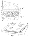
- Figure 1 is a cross-section through a cooking hob constructed in accordance with the utility model; and
- Figure 2 is a perspective view showing the possible use of the cooking hob of the utility model built into an item of furniture, such as a kitchen unit.
- With reference to said figures, a glass ceramic cooking hob is indicated overall by 1. It comprises a surface 2 which supports with direct contact usual containers 3 (only one is shown in Figure 1) containing food 1 to be subjected to preparation.
-
Several heating elements 5 are associated with the cooking hob 1, they being positioned below the hob. - In the example shown in the figures, the
elements 5 arehalogen lamps 6 powered in any known manner and of suitable (known) shape to heat thecxs 3 on the hob 1 by the heat generated during their operation. - In correspondence with and below the
lamps 6 there is provided a known screen or reflectingelement 10 arranged to suitably direct the light andheat rays 11 generated by said lamps towards the upperly positioned hob 1. - In particular, the
screen 10 is constructed of aluminium and comprises a series of concavities andconvexities 12 and 13 (with reference to the lamps), the concavities being positioned in correspondence with and below thelamps 6. - By this configuration the
screen 10 directs therays 11 substantially perpendicularly onto the hob 1, thus increasing the heating effect of the rays on the hob. - The
aluminium screen 10 has aface 15 facing thelamps 6 and aface 16 facing an external environment, such as acompartment 17 of a usualkitchen furniture unit 18. - According to the utility model, between said lamps and the reflecting
element 10 there is positioned abody 20 advantageously having the same shape as theelement 10 and lying parallel to it. - The
body 20 is formed of a material which is transparent to the light energy emitted by thelamps 6 but has a low capacity to conduct heat and a low refractive index, such as the usual constituent material of the glass ceramic hob. - The
body 20 divides thechamber 19 into twoportions portion 21, contains the lamp with the result that the air contained in it is subject to greater heating by virtue of their operation. Theother portion 22 is substantially insulated from theportion 21 by thebody 20, the air present in it being subject to lesser heating by virtue of the operation of thelamps 6. - Thus during the use of the cooking hob 1, the element or
screen 10 is less subject to heating by conduction deriving from the contact between the screen and the (hot) air present about the lamps. - The heating of the reflecting element is hence reduced overall, so preventing its temperature reaching a value critical or its mechanical stability.
- Any heat absorbed by the reflecting
element 10 is removed from it by natural or forced convention. - In this latter case, a
usual fan 24 driven by its own electric motor 25 (powered in known manner) is provided in thecompartment 17 to direct the air so that it grazes the element orscreen 10 and removes from it the heat absorbed by it during the operation of thelamps 6. - If the hob 1 is associated with the
furniture unit 18, anaperture 26 is provided in a wall 18A thereof to connect thecompartment 17 to the room containing the furniture unit 18 (such as a kitchen). Agrille 27 is placed over theaperture 26. - Consequently during the use of the hob 1 the
fan 24 is operated (either directly as a result of the operation oflamps 6 or via asuitable pushbutton 28 located on thecontrol panel 29 for theheat generators 5, or following the operation of thelamps 6 but with a suitable delay set by a usual timer connected to a usual electrical feed circuit for the lamps 6). - The operation of the fan causes cooling of the
screen 10, thus reducing its probability of suffering mechanical damage as a result of excessive overheating caused by the heat stored during the operation of thelamps 6. - A preferred embodiment of the utility model has been described. Modifications are however possible (such as positioning the
body 20 about thelamps 6 rather than as a continuous configuration as shown in Figure 1) which fall within the scope of the present utility model. - A cooking hob as described is of simple construction and enables possible malfunction deriving from damage to the screens or reflecting elements associated with its light and/or heat generators to be prevented, where such damage is related to excessive screen heating.
- In addition, the upper surface of said hob on which the food containers are placed for food preparation can be raised to a very high temperature with safety, so allowing better and quicker food treatment.
Claims (6)
- A glass ceramic cooking hob of the type comprising a surface on which containers containing food to be prepared are placed, below said surface there being provided at least one light and/or heat generator, such as a halogen lamp or the like, at which there is positioned an element reflecting the light and/or heat and having at least one face facing the generator or halogen lamp and an opposing face facing an external environment, said surface and said reflecting element defining a chamber in which said generator is located, characterised by comprising at least one body (20) between the light and/or heat generator (5) and the reflecting element (10), said body (20) being transparent to the energy emitted by the light and/or heat generator (5) and defining an interspace (22) at the reflecting element (10), so as to insulate this latter from a part (21) of the chamber (19), containing said generator (5), which is more sensitive to the heat generated during the operation of said generator (5).
- A cooking hob as claimed in claim 1, characterised in that the reflecting element (10) is exposed to an air flow generated by a fan (24) driven by its own electric motor (25).
- A cooking hob as claimed in claim 1, characterised in that the body (20) has the same shape as the reflecting element and is positioned, within the chamber (19) containing the light and/or heat generator (5), parallel to said element.
- A cooking hob as claimed in claim 1, characterised in that the body (20) is arranged around the light and/or heat generator (5).
- A cooking hob as claimed in claim 1 of the type associated with a known kitchen furniture unit, characterised in that the external environment is a compartment (17) within said furniture unit (18), said compartment opening to the outside of this latter via at least one suitable aperture (26) advantageously provided with a grille (27).
- A cooking hob as claimed in claim 2 and 5, characterised by comprising within the compartment (17) the fan (24) for cooling the reflecting element.
Applications Claiming Priority (3)
| Application Number | Priority Date | Filing Date | Title |
|---|---|---|---|
| ITMI910291 | 1991-04-05 | ||
| ITMI910291U | 1991-04-05 | ||
| IT000291 IT221794Z2 (en) | 1991-04-05 | 1991-04-05 | GLASS CERAMIC HOB IN WHICH A REFLECTIVE SURFACE ARRIVED IN CORRESPONDENCE WITH A LIGHT AND / OR HEAT GENERATOR, IN PARTICULAR A HALOGEN LAMP, IS PROTECTED FROM OVERHEATING |
Publications (3)
| Publication Number | Publication Date |
|---|---|
| EP0507248A2 true EP0507248A2 (en) | 1992-10-07 |
| EP0507248A3 EP0507248A3 (en) | 1993-06-16 |
| EP0507248B1 EP0507248B1 (en) | 1997-06-18 |
Family
ID=11358436
Family Applications (1)
| Application Number | Title | Priority Date | Filing Date |
|---|---|---|---|
| EP19920105515 Expired - Lifetime EP0507248B1 (en) | 1991-04-05 | 1992-03-31 | Glass ceramic cooking hob in which a reflecting surface in a position corresponding with a light and/or heat generator is protected against overheating |
Country Status (3)
| Country | Link |
|---|---|
| EP (1) | EP0507248B1 (en) |
| DE (1) | DE69220403T2 (en) |
| IT (1) | IT221794Z2 (en) |
Cited By (3)
| Publication number | Priority date | Publication date | Assignee | Title |
|---|---|---|---|---|
| FR2706022A1 (en) * | 1993-06-01 | 1994-12-09 | Jolly Marcel | Cooking apparatus with its receptacle |
| GB2367887A (en) * | 2000-10-09 | 2002-04-17 | Mindy Tsao | Electric oven with heat radiation reflection device |
| DE10240148A1 (en) * | 2002-08-30 | 2004-03-11 | BSH Bosch und Siemens Hausgeräte GmbH | hob for cooking has insert element fitting in groove between cooking field and service field |
Citations (3)
| Publication number | Priority date | Publication date | Assignee | Title |
|---|---|---|---|---|
| DE1275261B (en) * | 1955-01-10 | 1968-08-14 | Johann Achterfeld | Safety device on stoves fired with solid fuels and equipped with an electric or gas-powered top stove top |
| GB1433354A (en) * | 1973-05-04 | 1976-04-28 | Jenn Air Corp | Stove with selectively interchangeable cooking apparatus |
| DE3903540A1 (en) * | 1989-02-07 | 1990-08-09 | Guenter Petz | Radiant heater |
-
1991
- 1991-04-05 IT IT000291 patent/IT221794Z2/en active IP Right Grant
-
1992
- 1992-03-31 EP EP19920105515 patent/EP0507248B1/en not_active Expired - Lifetime
- 1992-03-31 DE DE1992620403 patent/DE69220403T2/en not_active Expired - Fee Related
Patent Citations (3)
| Publication number | Priority date | Publication date | Assignee | Title |
|---|---|---|---|---|
| DE1275261B (en) * | 1955-01-10 | 1968-08-14 | Johann Achterfeld | Safety device on stoves fired with solid fuels and equipped with an electric or gas-powered top stove top |
| GB1433354A (en) * | 1973-05-04 | 1976-04-28 | Jenn Air Corp | Stove with selectively interchangeable cooking apparatus |
| DE3903540A1 (en) * | 1989-02-07 | 1990-08-09 | Guenter Petz | Radiant heater |
Cited By (3)
| Publication number | Priority date | Publication date | Assignee | Title |
|---|---|---|---|---|
| FR2706022A1 (en) * | 1993-06-01 | 1994-12-09 | Jolly Marcel | Cooking apparatus with its receptacle |
| GB2367887A (en) * | 2000-10-09 | 2002-04-17 | Mindy Tsao | Electric oven with heat radiation reflection device |
| DE10240148A1 (en) * | 2002-08-30 | 2004-03-11 | BSH Bosch und Siemens Hausgeräte GmbH | hob for cooking has insert element fitting in groove between cooking field and service field |
Also Published As
| Publication number | Publication date |
|---|---|
| DE69220403T2 (en) | 1997-12-11 |
| EP0507248A3 (en) | 1993-06-16 |
| ITMI910291U1 (en) | 1992-10-05 |
| ITMI910291V0 (en) | 1991-04-05 |
| DE69220403D1 (en) | 1997-07-24 |
| EP0507248B1 (en) | 1997-06-18 |
| IT221794Z2 (en) | 1994-10-20 |
Similar Documents
| Publication | Publication Date | Title |
|---|---|---|
| US4868371A (en) | Heating assembly using tungsten-halogen lamps | |
| US6872921B1 (en) | Programmable slow-cooker appliance | |
| US5422460A (en) | Glass ceramic cooking hob with a reflecting surface arranged in a position corresponding with a light and/or heat generator, in particular a halogen lamp cooled by air circulation | |
| US4481405A (en) | Cooking appliance | |
| US3627986A (en) | Electric smooth top range | |
| EP0976975B1 (en) | Cooling device for halogen lamps in microwave ovens | |
| WO2000003183A3 (en) | Oven with combined convection and low mass, high power density heating | |
| CA2059010A1 (en) | Convection-radiant heated oven | |
| EP0507248B1 (en) | Glass ceramic cooking hob in which a reflecting surface in a position corresponding with a light and/or heat generator is protected against overheating | |
| EP0247574A1 (en) | Heating device for a microwave appliance | |
| GB2223093A (en) | Cookers | |
| GB2144956A (en) | Heating apparatus | |
| EP0162620A2 (en) | A cooking arrangement | |
| KR200393637Y1 (en) | The high-efficiency solar cooker equipped with a cool room | |
| CN215650521U (en) | General type electromagnetism electric kettle | |
| JP2784934B2 (en) | Cooker | |
| US3294955A (en) | Food warming apparatus | |
| ES1020588U (en) | Portable heating apparatus. (Machine-translation by Google Translate, not legally binding) | |
| CN215127555U (en) | Combined electric oven with top integrated electric ceramic oven | |
| EP0243025A3 (en) | Microwave ovens | |
| JP2835238B2 (en) | Electric cooker | |
| CN2148842Y (en) | Two-purpose cooling and warming fan with easily-separable electric heater | |
| KR100198835B1 (en) | A combined cooker and heater | |
| JPH02197721A (en) | Electric cooking apparatus | |
| JPS5572732A (en) | Electric cooker |
Legal Events
| Date | Code | Title | Description |
|---|---|---|---|
| PUAI | Public reference made under article 153(3) epc to a published international application that has entered the european phase |
Free format text: ORIGINAL CODE: 0009012 |
|
| AK | Designated contracting states |
Kind code of ref document: A2 Designated state(s): DE FR GB |
|
| RAP1 | Party data changed (applicant data changed or rights of an application transferred) |
Owner name: WHIRLPOOL EUROPE B.V. |
|
| PUAL | Search report despatched |
Free format text: ORIGINAL CODE: 0009013 |
|
| AK | Designated contracting states |
Kind code of ref document: A3 Designated state(s): DE FR GB |
|
| 17P | Request for examination filed |
Effective date: 19940217 |
|
| 17Q | First examination report despatched |
Effective date: 19951204 |
|
| GRAG | Despatch of communication of intention to grant |
Free format text: ORIGINAL CODE: EPIDOS AGRA |
|
| GRAH | Despatch of communication of intention to grant a patent |
Free format text: ORIGINAL CODE: EPIDOS IGRA |
|
| GRAH | Despatch of communication of intention to grant a patent |
Free format text: ORIGINAL CODE: EPIDOS IGRA |
|
| GRAA | (expected) grant |
Free format text: ORIGINAL CODE: 0009210 |
|
| AK | Designated contracting states |
Kind code of ref document: B1 Designated state(s): DE FR GB |
|
| REF | Corresponds to: |
Ref document number: 69220403 Country of ref document: DE Date of ref document: 19970724 |
|
| ET | Fr: translation filed | ||
| PLBE | No opposition filed within time limit |
Free format text: ORIGINAL CODE: 0009261 |
|
| STAA | Information on the status of an ep patent application or granted ep patent |
Free format text: STATUS: NO OPPOSITION FILED WITHIN TIME LIMIT |
|
| 26N | No opposition filed | ||
| PGFP | Annual fee paid to national office [announced via postgrant information from national office to epo] |
Ref country code: FR Payment date: 19990309 Year of fee payment: 8 |
|
| PGFP | Annual fee paid to national office [announced via postgrant information from national office to epo] |
Ref country code: GB Payment date: 19990401 Year of fee payment: 8 |
|
| PGFP | Annual fee paid to national office [announced via postgrant information from national office to epo] |
Ref country code: DE Payment date: 19990409 Year of fee payment: 8 |
|
| PG25 | Lapsed in a contracting state [announced via postgrant information from national office to epo] |
Ref country code: GB Free format text: LAPSE BECAUSE OF NON-PAYMENT OF DUE FEES Effective date: 20000331 |
|
| GBPC | Gb: european patent ceased through non-payment of renewal fee |
Effective date: 20000331 |
|
| PG25 | Lapsed in a contracting state [announced via postgrant information from national office to epo] |
Ref country code: FR Free format text: LAPSE BECAUSE OF NON-PAYMENT OF DUE FEES Effective date: 20001130 |
|
| REG | Reference to a national code |
Ref country code: FR Ref legal event code: ST |
|
| PG25 | Lapsed in a contracting state [announced via postgrant information from national office to epo] |
Ref country code: DE Free format text: LAPSE BECAUSE OF NON-PAYMENT OF DUE FEES Effective date: 20010103 |