EP0507233A2 - Burner for liquid fuels - Google Patents
Burner for liquid fuels Download PDFInfo
- Publication number
- EP0507233A2 EP0507233A2 EP92105438A EP92105438A EP0507233A2 EP 0507233 A2 EP0507233 A2 EP 0507233A2 EP 92105438 A EP92105438 A EP 92105438A EP 92105438 A EP92105438 A EP 92105438A EP 0507233 A2 EP0507233 A2 EP 0507233A2
- Authority
- EP
- European Patent Office
- Prior art keywords
- fuel
- housing
- inner housing
- burner according
- valve
- Prior art date
- Legal status (The legal status is an assumption and is not a legal conclusion. Google has not performed a legal analysis and makes no representation as to the accuracy of the status listed.)
- Withdrawn
Links
Images
Classifications
-
- F—MECHANICAL ENGINEERING; LIGHTING; HEATING; WEAPONS; BLASTING
- F23—COMBUSTION APPARATUS; COMBUSTION PROCESSES
- F23C—METHODS OR APPARATUS FOR COMBUSTION USING FLUID FUEL OR SOLID FUEL SUSPENDED IN A CARRIER GAS OR AIR
- F23C7/00—Combustion apparatus characterised by arrangements for air supply
- F23C7/008—Flow control devices
-
- F—MECHANICAL ENGINEERING; LIGHTING; HEATING; WEAPONS; BLASTING
- F23—COMBUSTION APPARATUS; COMBUSTION PROCESSES
- F23C—METHODS OR APPARATUS FOR COMBUSTION USING FLUID FUEL OR SOLID FUEL SUSPENDED IN A CARRIER GAS OR AIR
- F23C7/00—Combustion apparatus characterised by arrangements for air supply
- F23C7/002—Combustion apparatus characterised by arrangements for air supply the air being submitted to a rotary or spinning motion
- F23C7/004—Combustion apparatus characterised by arrangements for air supply the air being submitted to a rotary or spinning motion using vanes
-
- F—MECHANICAL ENGINEERING; LIGHTING; HEATING; WEAPONS; BLASTING
- F23—COMBUSTION APPARATUS; COMBUSTION PROCESSES
- F23D—BURNERS
- F23D11/00—Burners using a direct spraying action of liquid droplets or vaporised liquid into the combustion space
- F23D11/24—Burners using a direct spraying action of liquid droplets or vaporised liquid into the combustion space by pressurisation of the fuel before a nozzle through which it is sprayed by a substantial pressure reduction into a space
- F23D11/26—Burners using a direct spraying action of liquid droplets or vaporised liquid into the combustion space by pressurisation of the fuel before a nozzle through which it is sprayed by a substantial pressure reduction into a space with provision for varying the rate at which the fuel is sprayed
Landscapes
- Engineering & Computer Science (AREA)
- Chemical & Material Sciences (AREA)
- Combustion & Propulsion (AREA)
- Mechanical Engineering (AREA)
- General Engineering & Computer Science (AREA)
- Pressure-Spray And Ultrasonic-Wave- Spray Burners (AREA)
Abstract
Description
Die Erfindung betrifft einen Brenner zur Verbrennung von flüssigem Brennstoff, insbesondere leichtem Heizöl,
- mit einem Innengehäuse, das eine Brennstoffleitung umgibt und in dem primäre Verbrennungsluft förderbar ist,
- mit einem das Innengehäuse wenigstens teilweise umgebenden Außengehäuse, in dem sekundäre Verbrennungsluft förderbar ist,
- mit einer Gehäuseöffnung des Innengehäuses in deren Bereich ein Düsenkopf am Ende der Brennstoffleitung angeordnet ist,
- wobei mit dem Düsenkopf ein Brennstoff-Zerstäubungskegel erzeugbar ist, in den hinein die primäre und sekundäre Verbrennungsluft einleitbar sind,
- mit einem gegenüber Öffnungen im Außen- und/oder Innengehäuse beweglichen Überdeckungselement zur Veränderung des Querschnittes der Öffnungen, das mit einem die Zufuhr der Brennstoffmenge zur Brennstoffleitung steuernden Ventil verbunden ist.
- with an inner housing which surrounds a fuel line and in which primary combustion air can be conveyed,
- with an outer housing which at least partially surrounds the inner housing and in which secondary combustion air can be conveyed,
- with a housing opening of the inner housing in the area of which a nozzle head is arranged at the end of the fuel line,
- wherein the nozzle head can be used to generate a fuel atomization cone into which the primary and secondary combustion air can be introduced,
- with a covering element which is movable relative to openings in the outer and / or inner housing for changing the cross section of the openings and which is connected to a valve which controls the supply of the fuel quantity to the fuel line.
Bekannt ist aus der DE-PS 27 29 321 ein Brenner, dessen Brennstoffzuleitung in einem Düsenkopf endet. Leitung und Düse als sind "Lanze" beweglich in einem Gehäuse angeordnet. Die Düse ragt in einen Stutzen hinein, der Öffnungen aufweist. Durch die Leitung wird Heizöl zugeführt, das aus der Düse in Form eines Wirbels heraus-Als technisch schwierig erweist sich bei stöchiometrischen Brennern weiterhin die Art und Weise der Zündung, z.B. mit einer Zündelektrode. Nur ein "fettes" Gemisch, d.h. ein Gemisch mit einem Ölüberschuß, ist leicht zu entzünden.From DE-PS 27 29 321 a burner is known, the fuel feed ends in a nozzle head. Pipe and nozzle as "lance" are movably arranged in a housing. The nozzle protrudes into a nozzle that has openings. Heating oil is supplied through the line, which comes out of the nozzle in the form of a vortex The method of ignition, for example with an ignition electrode, continues to prove technically difficult in the case of stoichiometric burners. Only a "rich" mixture, ie a mixture with an excess of oil, is easy to ignite.
Bei den bekannten Brennern tritt aber ein solches zündfähiges Gemisch praktisch an keiner Stelle der Verbrennungszonen auf, so daß die Zündung mit Zündelektroden schwierig ist. Andere Zündvorrichtungen, insbesondere Zündlanzen, sind bekannt, aber in der Beschreibung und im Dauerbetrieb nicht optimal einzusetzen.In the known burners, however, such an ignitable mixture occurs practically at no point in the combustion zones, so that ignition with ignition electrodes is difficult. Other ignition devices, in particular ignition lances, are known, but cannot be optimally used in the description and in continuous operation.
Die eingangs erwähnten Schwierigkeiten der Zündung mit Elektroden sind daher zu beseitigen, um einen Brenner zu schaffen, dessen Zündung einfach und sicher ist, wobei die Vorteile der Steuerung der Eintrittsluft und der Brennstoffzufuhr erhalten bleiben soll.The difficulties of ignition with electrodes mentioned at the outset must therefore be eliminated in order to create a burner whose ignition is simple and safe, while maintaining the advantages of controlling the inlet air and the fuel supply.
Hierzu wird vorgeschlagen, eine zu einer Zündvorrichtung gehörende Zündungselektrode im Bereich der Außenfläche des Sprühkegels enden zu lassen, in dem das Sprühstrahl-Luft-Gemisch noch einen deutlich überstöchiometrischen, leicht zündfähigen Brennstoffanteil gegenüber Luft aufweist. Die erfinderische Lösung wird vor allem deshalb erreicht, da das Ende der Zündungselektrode an der Stelle angeordnet ist, an der ein "fettes" und damit leicht entzündbares Gemisch vorhanden ist, ohne daß dabei im übrigen die Zusammensetzung und die Betriebsweise des Brennstoff-Luft-Gemisches geändert werden muß.For this purpose, it is proposed to have an ignition electrode belonging to an ignition device end in the area of the outer surface of the spray cone, in which the spray jet / air mixture still has a clearly overstoichiometric, easily ignitable fuel component in relation to air. The inventive solution is mainly achieved because the end of the ignition electrode is located at the point where a "rich" and thus easily flammable mixture is present, without the rest of the composition and operation of the fuel-air mixture needs to be changed.
In vorteilhafter Ausgestaltung der Erfindung ist am Außengehäuse ein Einstellkopf befestigt, in dessen konischen Vorderteil Schlitze eingearbeitet sind. Zwischen Innengehäuse und Einstellkopf ist ein verstellbarer Ringkolben eingepaßt, der mit dem Stangenkolben verbindbar ist. Um den verstellbaren Ringkolben ist zum Einstellkopf hin ein Dichtungsring angeordnet. Dabei ist der Ringkolben vorzugsweise so lang, daß er in der vorgeschobenen Stellung die Schlitze vollkommen verschließt und in der zurückgeschobenen Stellung vollkommen freigibt. Durch die Veränderung des verstellbaren Ringkolbens ist die Luftzufuhr steuerbar. Dadurch, daß die Zündungselektrode und die Brennstoffleitung mit dem vorne angeordneten Düsenkopf in einer Stützvorrichtung verschiebbar angeordnet sind, sind noch feinere Abstimmungen hinsichtlich Zündung und Luftzufuhr möglich.In an advantageous embodiment of the invention, an adjustment head is fastened to the outer housing and slots are incorporated in the conical front part thereof. There is an adjustable ring piston between the inner housing and the adjustment head fitted, which is connectable to the rod piston. A sealing ring is arranged around the adjustable ring piston towards the adjustment head. The ring piston is preferably so long that it completely closes the slots in the advanced position and completely releases them in the retracted position. The air supply can be controlled by changing the adjustable ring piston. The fact that the ignition electrode and the fuel line with the nozzle head arranged at the front are arranged displaceably in a support device, even finer adjustments with regard to ignition and air supply are possible.
Die Erfindung wird nachstehend an einem Ausführungsbeispiel näher erläutert. Es zeigen
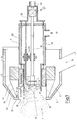
Figur 1- einen Längsschnitt durch einen Heizölbrenner;
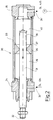
Figur 2- ein Ventil zur Einstellung der Brennstoffmengenzufuhr für vorgenannten Brenner;
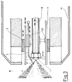
Figur 3- den vorderen Abschnitt eines anderen Heizölbren ners der gleichen Grundausführung wie
Figur 1; - Figur 4
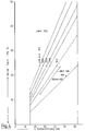
- ein Heizölbrennerdiagramm.
- Figure 1
- a longitudinal section through a heating oil burner;
- Figure 2
- a valve for adjusting the fuel supply for the aforementioned burner;
- Figure 3
- the front section of another Heizölbren ner of the same basic design as Figure 1;
- Figure 4
- a fuel oil burner diagram.
Figur 1 zeigt einen Längsschnitt durch einen Heizölbrenner, der mit einem herkömmlichen zerstäubenden Düsenkopf 1 ausgestattet ist. Derartige herkömmliche Zerstäuberdüsenköpfe, die unter Öldruck arbeiten, sind beispielsweise dem Buch von NIEPENBERG, Industrie-Ölfeuerungen; Verlag Kopf, Stuttgart, 2. Auflage, 1973, zu entnehmen. Der Düsenkopf 1 bildet das Ende einer Brennstoffzuleitung 8. Die Brennstoffzuleitung 8 verläuft zentral innerhalb eines Innengehäuses 7. Das Innengehäuse 7 besitzt eine zylindrische Wandung, die zum vorderen Teil des Brenners sich abgestuft verjüngt. Die aus dem Innengehäuse 7 ragende Brennstoffleitung 8 ist in einer Stützvorrichtung 20 gelagert. Die Ölzufuhr ist über ein Magnetventil 18 ein- und ausstellbar. Die Leitung 8 setzt sich über den in der Zeichnung genannten Verbindungpunkt A in Figur 2 fort.Figure 1 shows a longitudinal section through a heating oil burner, which is equipped with a conventional atomizing
Wie an sich bekannt, wird mit dem Düsenkopf 1 ein Zerstäubungskegel 16 aus feinsten Brennstoffteilchen erzeugt.As is known per se, an atomizing
Im vorderen Bereich endet das Innengehäuses 7 in einer Öffnung 9. Dort trägt das Innengehäuse an seiner Innenseite, bereits im äußeren Rand des Sprühkegels 16 angeordnet, Drallgeber 10, bestehend aus kleinen, quer gestellten Leitflächen, wie aus der Figur 1 ersichtlich. Am hinteren Teil des Innengehäuses 7 ist ein Stutzen 12 für die Zufuhr von Primärluft vorgesehen. Die Primärluft wird innerhalb des Innengehäuses 7 bis in den Bereich der Öffnung 9 geführt und mit Hilfe der Drallelemente 10 in eine Wirbelformation gebracht.In the front area, the
In der Stützvorrichtung 20 wird außerdem eine Leitung 3.1 einer Zündungs-Elektrode 3 gehalten, die abgewinkelt von der Leitung 3.1 vor der Düse 1 endet; mit ihrem anderen Ende ragt sie ebenso wie die Brennstoffleitung 8 aus dem Innengehäuse 7 heraus und ist in bekannter Weise mit einer Hochspannungsquelle (nicht dargestellt) verbunden und geschaltet.A line 3.1 of an
Den vorderen Teil des Innengehäuses 7 umschließt ein Außengehäuse 14 mit einem konischen Vorderteil 14.1. An Abschlußwandungen 21, die das Außengehäuse 14 nach vorne begrenzen und eine Öffnung 39 lassen, ist ein Einstellkopf 5 mit einem ebenfalls konischen Vorderteil 5.1 befestigt. Über einen Stutzen 15 wird sekundäre Luft in das Außengehäuse 14 eingeleitet.The front part of the
In das konische Vorderteil 5.1 sind Schlitze 19 eingebracht. Zwischen Einstellkopf 5 und Innengehäuse 7 ist ein verstellbarer, gleitender Ringkolben 2 eingepaßt, der über einen Dichtungsring 6 zum Einstellkopf 5 hin abgedichtet ist. Dieser Ringkolben 2 ist so breit, daß er die Schlitze 19 sowohl voll schließen als auch öffnen kann, so daß die Sekundärluft 15 entsprechend dosiert in den Bereich des Wirbels 11 eingeführt werden kann. Die Schlitze 19 können auch schräg in den Einstellkopf 5 eingefräst sein, so daß der durch die Schlitze geführte Luftstrom den durch die Drallvorrichtungen 10 erzeugten Wirbel 11 führt und verstärkt.
Der Ringkolben 2 ist über ein (schematisch dargestelltes) Gestänge 32 mit einem Stangenkolben 31 verbunden, der zu einem Brennstoffventil 30 gehört (vgl. Fig. 2). Das Brennstoffventil 30 besitzt ein zylindrisches Gehäuse 33, das an seinem vorderen Ende mit einem Verschluß 34 und an seinem hinteren Ende mit einem Verschluß 35 verschlossen ist. Beide Verschlüsse 34 und 35 sind über radiale Bohrungen gleichzeitig als Öleinlaß 34' bzw. als Ölauslaß 35' ausgestattet. Der Einlaß 34' ist mit einer entsprechenden Öldruckleitung (nicht dargestellt) und der Ölauslaß 35' mit der Leitung 8 gemäß Fig. 1 verbunden (vgl. Verbindungspunkt A).The
Das Gehäuse 33 trägt auf seiner Innenseite einen vorspringenden Flansch 36, der torusförmig ist und im Querschnitt die Form eines nach innen konvergierenden Trapezes hat. Der Flansch tangiert mit seiner Innenfläche 37 die Außenseite des Stangenkolben 31. Dieser trägt an seinem freien Ende eine keilförmige, zum Kolbeninneren vorspringenden Nut 38. Der Keilwinkel der Nut liegt etwa zwischen 2 und 10°. Diese Nut 38 ist jeweils von dem den Stangenkolben 31 umschließenden Flansch 36 nicht verschlossen, so daß das unter Druck stehende Öl in entsprechender Stellung des Stangenkolbens 31 beginnend mit der Menge Null zu einer größeren Menge pro Zeiteinheit fließen kann, so daß es vom Raum 39 in den Raum 40 innerhalb des zylindrischen Gehäuses 33 und von dort aus zum Ölauslaß 35' gelangen kann.The
Durch entsprechende Einstellung der Sekundärluftzufuhr läßt sich die stöchiometrische Menge an Luftzufuhr, die für das jeweilige Öl erforderlich ist, genau einstellen.By adjusting the secondary air supply accordingly, the stoichiometric amount of air supply required for the respective oil can be set precisely.
Wie aus der Figur 1 ersichtlich ist, können die Zündungs-Elektrode 3 und die Brennstoffleitung 8 mit der Düse 1 über die Stützeinrichtung 20 gegeneinander verstellt werden. Eine solche Verstellung ist normalerweise während des Betriebs nicht vorgesehen. Die Verstellmöglichkeit läßt sich jedoch dann beispielsweise einsetzen, wenn zu Beginn der Brennereinstellung eine bestimmte Zündeinstellung erforderlich ist oder wenn sich die Qualität und Zusammensetzung oder andere Parameter des flüssigen Brennstoffes ändern.As can be seen from FIG. 1, the
In Figur 3 ist ein vorderer Abschnitt eines anderen Heizölbrenners mit gleicher Grundausführung dargestellt. In einem Innengehäuse 7 ist über die Stützeinrichtung 20 die Brennstoffzuleitung 8 verstellbar angeordnet. Ebenso kann die Zündungs-Elektrode 3 verstellt werden. Die Düse 1 kann damit sowohl relativ gegenüber dem Gehäuse 7, dem Drallgeber 10 und der Zündungs-Elektrode 3 verstellt werden. Das Außengehäuse 14 ist von einer etwas anderen Gestalt. Auch hier ist der Ringkolben 2 mit dem Stangenkolben 31 zusammen verschiebbar.FIG. 3 shows a front section of another heating oil burner with the same basic design. The
Die Funktion der in den Figuren 1 und 3 dargestellten Vorrichtung ist wie folgt:
Über das Ventil 30 wird durch die Brennstoffzuleitung 8 die Heizölzufuhr zum Düsenkopf 1 gesteuert. Entsprechend der zugeführten Heizölmenge, abhängig von der Öffnung des Spaltes der Nut 38, wird die Zuluft entsprechend den Parametern und den Bedingungen der Stöchiometrie durch die Verstellung der Primärluft und Sekundärluft gesteuert. Die zum Einsatz kommende bekannte Düse 1 zerstäubt eine vom Düsenausgangsdruck abhängige Heizölmenge, die einen Zerstäubungskegel 16 mit einer Außenfläche 17 ergibt. Den Düsenkopf umgibt ein Drallgeber 10, der die Primärluft in einen Wirbel versetzt, der die feinen Heizöltröpfchen aufnimmt und in einem Wirbel führt. Dieser Wirbel wird noch verstärkt unter zusätzlicher Zerschlagung der Heizöltröpfchen bei Zutritt der Sekundärluft.The function of the device shown in Figures 1 and 3 is as follows:
The fuel oil supply to the
Wesentlich ist, daß unmittelbar nach Austritt, jedoch schon nach anfänglichem Hinzutreten der Primärluft ein zündfähiges Sprühstrahl-Luft-Gemisch vorhanden ist, wobei gewährleistet wird, daß sich die Zündungs-Elektrode 3 im Bereich der Außenfläche des Sprühkegels 16 endet, in dem das Sprühstrahl-Luft-Gemisch noch einen deutlich überstöchiometrischen, leicht zündbaren Brennstoffanteil gegenüber Luft aufweist. Das brennende und verwirbelte Brennstoff-Luft-Gemisch, das zunächst nicht vollständig verbrennt, wird im Laufe der Weiterführung und Wirbelstabilisierung über die sekundäre Luftzufuhr 15 weiter verbrannt, wobei die genauen stöchiometrischen Verhältnisse durch die Verstellung des Ringkolbens 2 und damit der Öffnung der Schlitze 19 regelbar ist. Indem die Abstände zwischen Ende Innengehäuse und Innenseite und Außenseite der Abschlußwandung 21 und Ringkolben 2 veränderbar sind, sind auch die Flammenlänge und -breite beeinflußbar.It is essential that an ignitable spray-air mixture is present immediately after the outlet, but already after the primary air has initially entered it, thereby ensuring that the
Aufschluß über die jeweils einzustellenden Mengen gibt das Diagramm gemäß Fig. 4, das wie folgt erläutert wird:
Auf der X-Achse ist die Kolbenöffnung, d.h. Verstellung des Kolbens 31 von einem Nullpunkt an, angegeben. Entsprechend dem Öldruck ist die durchlaufende Menge direkt proportional der Kolbenverstellung. Während die oberen Kurven diesen Zusammenhang bei einer Öldüse des Typs UMO 105 zeigen, zeigen die unteren Kurven den Zusammenhang bei einer Düse des Typs UMO 108. Gleichzeitig geben die Angaben in WS (mm Wassersäule) den erforderlichen Luftdruck an. Es handelt sich um willkürlich gewählte Parameter bei einer bestimmten Ausführungsform. Es zeigt sich, daß das Prinzip der Erfindung insbesondere für Brenner mit großer Energieerzeugung einsetzbar ist.The diagram according to FIG. 4, which is explained as follows, provides information about the quantities to be set:
The piston opening, ie adjustment of the
Claims (8)
daß an der Gehäuse-Innenseite ein vorspringender, die Außenseite des Stangenkolbens (31) umschießender Flansch (36) angeordnet ist,
und daß der Stangenkolben (31) auf wenigstens einem Teil seiner Länge eine Nut (38) aufweist, die über ihre Länge mit variabler Tiefe ausgestattet ist und die von der sie überdeckenden Innenseite des Flansches (36) nicht verschlossen ist.Burners for the combustion of liquid fuel, in particular light heating oil,
that a projecting flange (36) surrounding the outside of the rod piston (31) is arranged on the inside of the housing,
and that the rod piston (31) has at least part of its length a groove (38) which is provided with a variable depth over its length and which is not closed by the inside of the flange (36) covering it.
Applications Claiming Priority (2)
| Application Number | Priority Date | Filing Date | Title |
|---|---|---|---|
| DE9103964U DE9103964U1 (en) | 1991-04-02 | 1991-04-02 | |
| DE9103964U | 1991-04-02 |
Publications (2)
| Publication Number | Publication Date |
|---|---|
| EP0507233A2 true EP0507233A2 (en) | 1992-10-07 |
| EP0507233A3 EP0507233A3 (en) | 1993-02-24 |
Family
ID=6865881
Family Applications (1)
| Application Number | Title | Priority Date | Filing Date |
|---|---|---|---|
| EP19920105438 Withdrawn EP0507233A3 (en) | 1991-04-02 | 1992-03-30 | Burner for liquid fuels |
Country Status (2)
| Country | Link |
|---|---|
| EP (1) | EP0507233A3 (en) |
| DE (1) | DE9103964U1 (en) |
Cited By (14)
| Publication number | Priority date | Publication date | Assignee | Title |
|---|---|---|---|---|
| DE10164217A1 (en) * | 2001-12-31 | 2003-07-17 | Jochen Schanze | Gas or liquid fuel operated burner for heating incorporates swirl element with hub-and ring-discs, blades, cylindrical housing, adjustment for overflow air |
| US6866502B2 (en) | 2002-03-16 | 2005-03-15 | Exxonmobil Chemical Patents Inc. | Burner system employing flue gas recirculation |
| US6877980B2 (en) | 2002-03-16 | 2005-04-12 | Exxonmobil Chemical Patents Inc. | Burner with low NOx emissions |
| US6881053B2 (en) | 2002-03-16 | 2005-04-19 | Exxonmobil Chemical Patents Inc. | Burner with high capacity venturi |
| US6884062B2 (en) | 2002-03-16 | 2005-04-26 | Exxonmobil Chemical Patents Inc. | Burner design for achieving higher rates of flue gas recirculation |
| US6887068B2 (en) | 2002-03-16 | 2005-05-03 | Exxonmobil Chemical Patents Inc. | Centering plate for burner |
| US6890171B2 (en) | 2002-03-16 | 2005-05-10 | Exxonmobil Chemical Patents, Inc. | Apparatus for optimizing burner performance |
| US6890172B2 (en) | 2002-03-16 | 2005-05-10 | Exxonmobil Chemical Patents Inc. | Burner with flue gas recirculation |
| US6893252B2 (en) | 2002-03-16 | 2005-05-17 | Exxonmobil Chemical Patents Inc. | Fuel spud for high temperature burners |
| US6893251B2 (en) | 2002-03-16 | 2005-05-17 | Exxon Mobil Chemical Patents Inc. | Burner design for reduced NOx emissions |
| US6986658B2 (en) | 2002-03-16 | 2006-01-17 | Exxonmobil Chemical Patents, Inc. | Burner employing steam injection |
| WO2007051698A1 (en) * | 2005-11-04 | 2007-05-10 | Alstom Technology Ltd | Burner lance |
| US7322818B2 (en) | 2002-03-16 | 2008-01-29 | Exxonmobil Chemical Patents Inc. | Method for adjusting pre-mix burners to reduce NOx emissions |
| US7476099B2 (en) * | 2002-03-16 | 2009-01-13 | Exxonmobil Chemicals Patents Inc. | Removable light-off port plug for use in burners |
Citations (6)
| Publication number | Priority date | Publication date | Assignee | Title |
|---|---|---|---|---|
| FR1211598A (en) * | 1957-08-27 | 1960-03-17 | Int Combustion Holdings Ltd | Installation of liquid fuel burners |
| NL224008A (en) * | 1958-01-14 | 1960-11-15 | ||
| US2976885A (en) * | 1955-07-08 | 1961-03-28 | Orr & Sembower Inc | Fuel control valves |
| DE2457139A1 (en) * | 1974-07-05 | 1976-01-22 | Samat Apparatebau Gmbh Innsbru | Control of oil supply to burner jet - for partial load and full load operation with additional control of air supply |
| DE2624649A1 (en) * | 1976-06-02 | 1977-12-15 | Danfoss As | Oil burner for small oil flow rates - has nozzle inner and outer tube distributing primary and secondary air |
| EP0000358A2 (en) * | 1977-06-29 | 1979-01-24 | Smit Ovens Nijmegen B.V. | Method for controlling the combustion of liquid fuels, and burner arrangement suitable for carrying out the method |
-
1991
- 1991-04-02 DE DE9103964U patent/DE9103964U1/de not_active Expired - Lifetime
-
1992
- 1992-03-30 EP EP19920105438 patent/EP0507233A3/en not_active Withdrawn
Patent Citations (6)
| Publication number | Priority date | Publication date | Assignee | Title |
|---|---|---|---|---|
| US2976885A (en) * | 1955-07-08 | 1961-03-28 | Orr & Sembower Inc | Fuel control valves |
| FR1211598A (en) * | 1957-08-27 | 1960-03-17 | Int Combustion Holdings Ltd | Installation of liquid fuel burners |
| NL224008A (en) * | 1958-01-14 | 1960-11-15 | ||
| DE2457139A1 (en) * | 1974-07-05 | 1976-01-22 | Samat Apparatebau Gmbh Innsbru | Control of oil supply to burner jet - for partial load and full load operation with additional control of air supply |
| DE2624649A1 (en) * | 1976-06-02 | 1977-12-15 | Danfoss As | Oil burner for small oil flow rates - has nozzle inner and outer tube distributing primary and secondary air |
| EP0000358A2 (en) * | 1977-06-29 | 1979-01-24 | Smit Ovens Nijmegen B.V. | Method for controlling the combustion of liquid fuels, and burner arrangement suitable for carrying out the method |
Cited By (17)
| Publication number | Priority date | Publication date | Assignee | Title |
|---|---|---|---|---|
| DE10164217A1 (en) * | 2001-12-31 | 2003-07-17 | Jochen Schanze | Gas or liquid fuel operated burner for heating incorporates swirl element with hub-and ring-discs, blades, cylindrical housing, adjustment for overflow air |
| DE10164217B4 (en) * | 2001-12-31 | 2004-08-05 | Jochen Schanze | Burner for a building heating system |
| US6890172B2 (en) | 2002-03-16 | 2005-05-10 | Exxonmobil Chemical Patents Inc. | Burner with flue gas recirculation |
| US6893252B2 (en) | 2002-03-16 | 2005-05-17 | Exxonmobil Chemical Patents Inc. | Fuel spud for high temperature burners |
| US6881053B2 (en) | 2002-03-16 | 2005-04-19 | Exxonmobil Chemical Patents Inc. | Burner with high capacity venturi |
| US6884062B2 (en) | 2002-03-16 | 2005-04-26 | Exxonmobil Chemical Patents Inc. | Burner design for achieving higher rates of flue gas recirculation |
| US6887068B2 (en) | 2002-03-16 | 2005-05-03 | Exxonmobil Chemical Patents Inc. | Centering plate for burner |
| US6890171B2 (en) | 2002-03-16 | 2005-05-10 | Exxonmobil Chemical Patents, Inc. | Apparatus for optimizing burner performance |
| US6866502B2 (en) | 2002-03-16 | 2005-03-15 | Exxonmobil Chemical Patents Inc. | Burner system employing flue gas recirculation |
| US6877980B2 (en) | 2002-03-16 | 2005-04-12 | Exxonmobil Chemical Patents Inc. | Burner with low NOx emissions |
| US6893251B2 (en) | 2002-03-16 | 2005-05-17 | Exxon Mobil Chemical Patents Inc. | Burner design for reduced NOx emissions |
| US6902390B2 (en) | 2002-03-16 | 2005-06-07 | Exxonmobil Chemical Patents, Inc. | Burner tip for pre-mix burners |
| US6986658B2 (en) | 2002-03-16 | 2006-01-17 | Exxonmobil Chemical Patents, Inc. | Burner employing steam injection |
| US7025587B2 (en) | 2002-03-16 | 2006-04-11 | Exxonmobil Chemical Patents Inc. | Burner with high capacity venturi |
| US7476099B2 (en) * | 2002-03-16 | 2009-01-13 | Exxonmobil Chemicals Patents Inc. | Removable light-off port plug for use in burners |
| US7322818B2 (en) | 2002-03-16 | 2008-01-29 | Exxonmobil Chemical Patents Inc. | Method for adjusting pre-mix burners to reduce NOx emissions |
| WO2007051698A1 (en) * | 2005-11-04 | 2007-05-10 | Alstom Technology Ltd | Burner lance |
Also Published As
| Publication number | Publication date |
|---|---|
| DE9103964U1 (en) | 1992-07-30 |
| EP0507233A3 (en) | 1993-02-24 |
Similar Documents
| Publication | Publication Date | Title |
|---|---|---|
| DE2731562C2 (en) | Burners for liquid and / or gaseous fuels | |
| EP0321809B1 (en) | Process for combustion of liquid fuel in a burner | |
| EP0507233A2 (en) | Burner for liquid fuels | |
| DE2828826A1 (en) | BURNER FOR LIQUID FUEL | |
| EP0636836A2 (en) | Burner for burning pulverulent fuel | |
| DE2729321C2 (en) | Process for the combustion of liquid fuel and burner device for carrying out the process | |
| DE1992618U (en) | GAS BURNER. | |
| DE2806363C2 (en) | Method of igniting the combustion of coal dust | |
| DE2553953C2 (en) | Liquid fuel burners | |
| EP0683883B1 (en) | Blue-flame burner with optimized combustion characteristics | |
| EP1030106B1 (en) | Blue-flame burner with optimized combustion characteristics | |
| EP0857915A2 (en) | Method and burner head for the combustion of liquid and gaseous fuels | |
| DE1501833A1 (en) | Process for generating a flame jet and burner for performing this process | |
| DE3718994C2 (en) | ||
| WO1979000468A1 (en) | Oil-burner for low heating powers and process for its operation | |
| DE2345838A1 (en) | BURNER | |
| DE3424031A1 (en) | METHOD FOR BURNING A LIQUID OR SOLID, POWDERED FUEL | |
| DE2820297A1 (en) | Glow ignited oil of gas burner - has additional consumable tube for flame arranged upstream of combustion space tube | |
| DE2538134C2 (en) | Oil burner | |
| EP0683884B1 (en) | Adjustable blue-flame burner | |
| DE2633634A1 (en) | METHOD AND DEVICE FOR IGNITING A FLAME FUELED WITH FLAME RESISTANT LIQUID FUEL | |
| DE2900142A1 (en) | OIL BURNER WITH CHANGEABLE FLAME SHAPE | |
| DE4229525A1 (en) | Mixing system for oil-atomising burner - has baffle plate forming bottom of vaporising cup inside tapering flame tube | |
| DE19860785A1 (en) | Atomizer to atomize liquid fuel in combustion chamber of gas turbine, for example, has fluidic device with annular outer channel formed between outer and inner pipe and delivering fluid under pressure to interact with spray cone | |
| CH650067A5 (en) | Oil-atomising burner |
Legal Events
| Date | Code | Title | Description |
|---|---|---|---|
| PUAI | Public reference made under article 153(3) epc to a published international application that has entered the european phase |
Free format text: ORIGINAL CODE: 0009012 |
|
| AK | Designated contracting states |
Kind code of ref document: A2 Designated state(s): AT BE CH DE DK ES FR GB GR IT LI LU MC NL PT SE |
|
| PUAL | Search report despatched |
Free format text: ORIGINAL CODE: 0009013 |
|
| AK | Designated contracting states |
Kind code of ref document: A3 Designated state(s): AT BE CH DE DK ES FR GB GR IT LI LU MC NL PT SE |
|
| 17P | Request for examination filed |
Effective date: 19930824 |
|
| 17Q | First examination report despatched |
Effective date: 19941110 |
|
| STAA | Information on the status of an ep patent application or granted ep patent |
Free format text: STATUS: THE APPLICATION IS DEEMED TO BE WITHDRAWN |
|
| 18D | Application deemed to be withdrawn |
Effective date: 19951003 |