EP0506708B1 - Verfahren und gerät zur statistischen fm-rauschunterdrückung - Google Patents
Verfahren und gerät zur statistischen fm-rauschunterdrückung Download PDFInfo
- Publication number
- EP0506708B1 EP0506708B1 EP91900439A EP91900439A EP0506708B1 EP 0506708 B1 EP0506708 B1 EP 0506708B1 EP 91900439 A EP91900439 A EP 91900439A EP 91900439 A EP91900439 A EP 91900439A EP 0506708 B1 EP0506708 B1 EP 0506708B1
- Authority
- EP
- European Patent Office
- Prior art keywords
- envelope
- noise
- pulses
- amplitude
- signal
- Prior art date
- Legal status (The legal status is an assumption and is not a legal conclusion. Google has not performed a legal analysis and makes no representation as to the accuracy of the status listed.)
- Expired - Lifetime
Links
- 238000000034 method Methods 0.000 title claims abstract description 27
- 238000012545 processing Methods 0.000 claims description 12
- 230000004044 response Effects 0.000 claims description 7
- 238000001914 filtration Methods 0.000 claims description 4
- 238000005070 sampling Methods 0.000 claims description 3
- 238000005562 fading Methods 0.000 abstract description 27
- 238000004422 calculation algorithm Methods 0.000 abstract description 13
- 230000008569 process Effects 0.000 description 6
- 230000003111 delayed effect Effects 0.000 description 4
- 238000001514 detection method Methods 0.000 description 4
- 230000011664 signaling Effects 0.000 description 4
- 238000013459 approach Methods 0.000 description 3
- 238000013480 data collection Methods 0.000 description 3
- 230000000694 effects Effects 0.000 description 3
- 238000005259 measurement Methods 0.000 description 3
- 238000009795 derivation Methods 0.000 description 2
- 238000010586 diagram Methods 0.000 description 2
- 230000004069 differentiation Effects 0.000 description 2
- 230000006870 function Effects 0.000 description 2
- 230000002411 adverse Effects 0.000 description 1
- 230000008901 benefit Effects 0.000 description 1
- 230000005540 biological transmission Effects 0.000 description 1
- 238000004364 calculation method Methods 0.000 description 1
- 239000003990 capacitor Substances 0.000 description 1
- 230000015556 catabolic process Effects 0.000 description 1
- 238000012512 characterization method Methods 0.000 description 1
- 238000004891 communication Methods 0.000 description 1
- 238000005094 computer simulation Methods 0.000 description 1
- 238000006731 degradation reaction Methods 0.000 description 1
- 230000001934 delay Effects 0.000 description 1
- 230000001419 dependent effect Effects 0.000 description 1
- 238000012986 modification Methods 0.000 description 1
- 230000004048 modification Effects 0.000 description 1
- 238000001228 spectrum Methods 0.000 description 1
- 238000012546 transfer Methods 0.000 description 1
- 230000001960 triggered effect Effects 0.000 description 1
Images

Classifications
-
- H—ELECTRICITY
- H03—ELECTRONIC CIRCUITRY
- H03G—CONTROL OF AMPLIFICATION
- H03G3/00—Gain control in amplifiers or frequency changers
- H03G3/20—Automatic control
- H03G3/30—Automatic control in amplifiers having semiconductor devices
- H03G3/32—Automatic control in amplifiers having semiconductor devices the control being dependent upon ambient noise level or sound level
-
- H—ELECTRICITY
- H04—ELECTRIC COMMUNICATION TECHNIQUE
- H04B—TRANSMISSION
- H04B15/00—Suppression or limitation of noise or interference
-
- H—ELECTRICITY
- H03—ELECTRONIC CIRCUITRY
- H03G—CONTROL OF AMPLIFICATION
- H03G3/00—Gain control in amplifiers or frequency changers
- H03G3/20—Automatic control
- H03G3/22—Automatic control in amplifiers having discharge tubes
- H03G3/26—Muting amplifier when no signal is present
- H03G3/28—Muting amplifier when no signal is present in frequency-modulation receivers
-
- H—ELECTRICITY
- H04—ELECTRIC COMMUNICATION TECHNIQUE
- H04B—TRANSMISSION
- H04B1/00—Details of transmission systems, not covered by a single one of groups H04B3/00 - H04B13/00; Details of transmission systems not characterised by the medium used for transmission
- H04B1/06—Receivers
- H04B1/10—Means associated with receiver for limiting or suppressing noise or interference
- H04B1/12—Neutralising, balancing, or compensation arrangements
Definitions
- This invention relates generally to FM (frequency modulation) radio communication systems and in particular to FM radio systems based on digital signal processing (DSP) techniques, and is more particularly directed toward a method for cancelling random FM noise caused by undesired phase modulation of the transmitted signal induced by a fading transmission channel.
- DSP digital signal processing
- Rayleigh fading refers to the rapid fluctuation in the magnitude and phase of a received signal resulting from multipath propagation. This Rayleigh-faded signal is most objectionable to a listener when the magnitude of the fade is large enough to cause a substantial momentary decrease in the received signal amplitude. This results in the listener hearing an objectionable burst of noise.
- the technique described in the above-cited Application involves a mixing operation (multiplication of two or more signals), which can result in sub-audible imbedded signalling, such as tone-coded squelch or low-speed trunking data, being translated into the audible portion of the spectrum, causing an objectionable rumbling in receiver audio.
- sub-audible imbedded signalling such as tone-coded squelch or low-speed trunking data
- US -A- 4,166,251 discloses a system comprising a demodulator for demodulating an input FM signal which has been subjected to interference by another FM signal, an envelope detector for detecting the envelope of fluctuation of the amplitude of the input signal, an AGC circuit for controlling the level of the input signal supplied to the envelope detector, a capacitor for passing only the AC component of the output of the envelope detector, a circuit having a transfer characteristic of a hyperbolic function and converting the waveform of the AC component, an analog multiplier supplied at its "x" input terminal with an output of the waveform converting circuit and producing a distortion cancellation signal, a first operation circuit supplied with the output signal of the demodulator and with the distortion cancellation signal and carrying out an operation such as substantially cancelling the interference distortion of the demodulated signal with the distortion cancellation signal, a delay circuit for delaying the output signal of the first operation circuit or of the demodulator by a specific time, and a second operation circuit supplied with the output signal of the first operation circuit or of the demodulator and with the output
- DSP digital signal processor
- a technique is needed that counteracts the effects of a fading event, rather than muting the audio.
- a method for cancelling random FM noise that substantially eliminates discriminator output noise pulses, the method being substantially in accordance with claim 1 herein described.
- the random FM noise cancellation method of the present invention uses information contained in the fading envelope ( ⁇ (t)) to effectively cancel random FM noise pulses at the discriminator output.
- the pulse amplitude and shape are obtained from the envelope, while the pulse direction (sign) is obtained by proper filtering of the discriminator output signal.
- the effectiveness of the instant invention hinges on the assumption that the real and imaginary parts of the fading parameter are approximately linear for the duration of the noise pulses.
- the real and imaginary parts of r(t) are approximately linear. That is: x(t) ⁇ m x t + b x and y(t) ⁇ m y t + b y This assumption is entirely reasonable and defensible for two reasons.
- Rayleigh (or Rician, multipath, etc.) fading is a lowpass process.
- the signal will be approximately linear.
- the objectionable noise pulses caused by fading generally have widths that are considerably less than the minimum period of the process. This linear assumption is especially valid during envelope minima, at which times the noise pulses are generated.
- Fig. 1 illustrates the real part (102) and imaginary part (103) of a two ray fading parameter, as well as the resultant magnitude (101).
- a two ray fade consists of the direct reception of the desired signal plus one additional reflected signal, with the amplitudes of both signals remaining constant.
- the real part (102) and imaginary part (103) of the fading parameter are the most linear during envelope minima.
- Fig. 2 depicts the real part (202) and imaginary part (203) of a Rayleigh fading parameter and the resultant magnitude (201). Although the effect is less obvious with a Rayleigh fading parameter than with a two ray fade, the real part (202) and imaginary part (203) are still most likely to be linear around the envelope minima as the Figure shows.
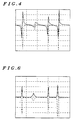
- Fig. 4 shows noise pulses at the discriminator output by a dashed line, with the normalized envelope derivative depicted by a solid line. From an examination of the Figure, it is apparent that the noise pulse magnitude is equal to the peak-to-peak value of the normalized derivative.
- Pulse direction can be detected by proper filtering of the discriminator output signal. If no sub-audible signaling is present, such as coded squelch or low-speed trunking data, the pulse direction can be detected via a low pass filter. In the case of sub-audible signaling, a properly designed low pass or band pass filter will serve to determine pulse direction. In some instances (i.e., where the bandwidth of the message signal is lowpass), a high pass filter may be employed to determine pulse direction.
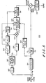
- FIG. 5 A block diagram of the preferred implementation of the method of the present invention is shown in Fig. 5, as generally depicted by the number 500. Since the method is designed for use in a digitally implemented radio, the noise cancellation algorithm is implemented using a DSP, preferably a DSP56000 family device manufactured by Motorola, Inc.
- the algorithm receives its input from a digital IF filter, in the form of a sequence of complex samples, at the input of the discriminator (501).
- the algorithm necessarily runs at the discriminator sampling rate.
- the magnitude of each complex sample at the discriminator is calculated in block 502. These magnitude samples constitute the raw envelope (p) of the received signal.
- This envelope signal is then filtered by the envelope low pass filter (LPF) (503).
- the envelope LPF (503) is required to reduce the effects of noise and IF filter-induced ripple on the envelope. Since a filter introduces a delay to the calculation performed by the algorithm, the envelope LPF (503) is preferably linear phase and symmetric in order that the delay introduced will be an integral number of sample periods. Restricting filter delay to an integral number of sample periods simplifies alignment of generated counter pulses with actual noise pulses, which will be discussed in more detail below.
- the envelope LPF is implemented in the DSP as a symmetric finite impulse response (FIR) filter with an odd number of taps.
- FIR finite impulse response
- the output of the envelope LPF (503), designated in Fig. 5 as p 1 is processed via two parallel paths.
- the derivative of p 1 is calculated in differentiation block 504.
- the expression appearing within block 504, 1 z -1 is one possible z-transform approximation of differentiation, as is known in the art, and introduces a delay of one-half a sample period.
- the upper path includes a two-tap filter (505) that adds a one-half sample period delay.
- the expression [1 + z -1 ]/2 is one possible z-transform implementation of an appropriate delay process.
- the delayed envelope is subjected to an inversion operation (506), then the envelope derivative and the inverted envelope are multiplied in block 507 to yield the normalized derivative.
- the sign of the counter pulse is estimated by a pulse sign filter (508) that uses, as input, the output of the discriminator (501).
- the filter must be designed such that its passband covers a frequency region which contains minimal energy from normal audio, and any subaudible signaling, while maximizing noise pulse energy. Since random FM noise pulses are lowpass in nature, the sign filter passband must reside in some frequency region below the normal audio cutoff frequency of 300 Hz.
- the impulse response of the sign filter should be short, with only one dominant lobe, in order to minimize inter noise pulse interference. Noise pulses that are bad enough to necessitate cancellation look essentially like impulses to the sign filter.
- the sign estimation delay from the detected pulse center is equal to the delay to the maximum amplitude excursion of the filter's impulse response.
- the normalized derivative computed in block 507 of Fig. 5 triggers the algorithm to begin collecting data for the creation of the counter pulse when it crosses the pulse detection threshold indicated in Fig. 3.
- data collection is triggered by the normalized derivative crossing a minimum threshold in the preferred embodiment, data collection could also be initiated through the normalized derivative crossing a maximum threshold, or the absolute value of the normalized derivative exceeding a predetermined threshold value.
- the pulse detection and measurement block (509) detects this threshold crossing, and begins searching for the local minimum of g(t) (g min ) between the threshold crossing and the zero crossing.
- the local maximum (g max ) is then located, and the absolute value of the pulse amplitude is calculated as described above.
- the output of the pulse sign filter (508) yields a sign estimate.
- the pulse shape is determined by the square of the ratio of the envelope value at the pulse center ( ⁇ (t m )) to the envelope amplitude around the fade event ( ⁇ (t)).
- the envelope amplitude value at the pulse center is determined from the delayed envelope passed to the pulse detection and measurement block (509) from delay process 505.
- the final pulse shape determination is made in the pulse generator block (510) through multiplication by properly delayed (by ⁇ i ) samples of the inverse envelope provided by a delay line (511).
- the pulse detection and measurement block (509) provides the necessary information regarding pulse amplitude and sign to the pulse generator (510).
- the output of the discriminator (501) is also input to a delay line (512) of length ⁇ c , where ⁇ c denotes the cancellation delay.
- the cancellation delay represents the minimum audio delay necessary for the algorithm to operate correctly, and thus must be known exactly as well.
- the noise pulses at the output of the delay line (512) and the properly aligned counter pulses from the pulse generator (510) are added together in a summer (513) before being processed by a simple de-emphasis filter (514) to yield the final audio output.
- Fig. 6 depicts counter pulses (solid line) and noise pulses (dashed line) properly aligned for noise cancellation.
- the normalized derivative Under good operating conditions, the normalized derivative, as depicted in Fig. 3, will have only one zero crossing during the collection period. However, at low S/N, the normalized derivative becomes a function of noise in addition to the desired envelope signal. Under these conditions, the normalized derivative will have significantly more zero crossings. Additional extraneous zero crossing events are also caused by high frequency envelope ripple due to interference or frequency selective fading. Accordingly, whenever a second zero crossing occurs unexpectedly within a predetermined time after the initial zero crossing, data collection is disabled and the algorithm is reset.
- a third possible error condition may occur during computation of the shape of the counter pulse.
- the shape is the square of the ratio of the envelope minimum to the amplitude of envelope samples around the noise pulse event. This ratio should always be less than or equal to one, since the envelope minimum itself is the local minimum of envelope sample amplitudes around the noise pulse event. If this ratio is greater than one, an error has occurred, and the pulse amplitude estimate is set to zero to prevent a non-zero counter pulse from being added to the discriminator output.
Landscapes
- Engineering & Computer Science (AREA)
- Computer Networks & Wireless Communication (AREA)
- Signal Processing (AREA)
- Noise Elimination (AREA)
Claims (8)
- Verfahren zum Unterdrücken von statistischem FM-Rauschen für ein FM-moduliertes HF-Signal mit einer Hüllkurve, das Rauschimpulse am Ausgang eines Diskriminators im wesentlichen beseitigt, wobei das Verfahren die folgenden Schritte umfaßt:(a) Verarbeiten (502, 503, 504, 505, 506, 507, 509, 510, 511) der Hüllkurve des FM-modulierten Signals, um Eigenschaften zu bestimmen, die Form, Amplitude und Zeit des Auftretens von Rauschimpulsen anzeigen, wobei der Schritt (a) der Verarbeitung der Hüllkurve des FM-modulierten Signals weiter die folgenden Schritte umfaßt: (a1) Differenzieren (504) der Hüllkurve, um eine Hüllkurvenableitung zu gewinnen, (a2) Teilen (507) der Hüllkurvenableitung durch die Hüllkurve, um eine normalisierte Ableitung hervorzubringen, (a3) Berechnen (509) der Spitze-Spizte-Amplitude der normalisierten Ableitung, um die Rauschimpulsamplitude zu gewinnen, (a4) Berechnen (509) der Zeit des Auftretens von Hüllkurvenminima, um die Zeit des Auftretens von Rauschimpulsen zu gewinnen, und (a5) Berechnen (509) des Quadrates des Verhältnisses der Hüllkurvenamplitude bei Hüllkurvenminima zu der Hüllkurvenamplitude um Hüllkurvenminima, um die Rauschimpulsform zu gewinnen;(b) Verarbeiten (508, 509) des Diskriminatorausgangssignals, um wenigstens eine Eigenschaft zu bestimmen, die die Richtung des Rauschimpulses anzeigt;(c) Erzeugen (510) von Gegenimpulsen auf der Grundlage der in den Schritten (a) und (b) bestimmten Eigenschaften und(d) Kombinieren (513) der Gegenimpulse und des Diskriminatorausgangs, um die statistischen FM-Rauschimpulse im wesentlichen zu unterdrücken.
- Verfahren nach Anspruch 1, bei dem die Verarbeitungsschritte (a3) bis (a5) nur ausgeführt werden, wenn die Amplitude der normalisierten Ableitung eine vorbestimmte Schwelle kreuzt.
- Verfahren nach Anspruch 1, bei dem die Verarbeitungsschritte (a3) bis (a5) beendet werden, wenn die normalisierte Ableitung mehr als einen Nulldurchgang innerhalb einer vorbestimmten Zeit aufweist.
- Verfahren nach Anspruch 1, bei dem der Schritt (b) der Verarbeitung des Diskriminatorausgangssignals weiter die Schritte umfaßt:(b1) Filtern (508) des Diskriminatorausgangssignals, um ein gefiltertes Signal zu gewinnen, und(b2) Abtasten (509) des gefilterten Signals, um die Rauschimpulsrichtung zu gewinnen.
- Verfahren nach Anspruch 4, bei dem das gefilterte Signal bei einer Zeit abgetastet wird, die im wesentlichen mit dem maximalen Amplitudenausschlag des Impulsansprechens des Filters zusammenfällt.
- Verfahren nach Anspruch 1, bei dem der Schritt (d) des Kombinierens der Gegenimpulse und des Diskriminatorausgangs das Addieren (513) der Gegenimpulse und des Diskriminatorausgangs umfaßt.
- Vorrichtung zum Unterdrücken von statistischem FM-Rauschen für ein FM-moduliertes HF-Signal mit einer Hüllkurve, die Rauschimpulse am Ausgang eines Diskriminators im wesentlichen beseitigt, wobei die Vorrichtung umfaßt:eine Einrichtung zum Verarbeiten (502, 503, 504, 505, 506, 507, 509, 510, 511) der Hüllkurve des FM-modulierten Signals, um erste Eigenschaften zu bestimmen, die Form, Amplitude und Zeit des Auftretens von Rauschimpulsen anzeigen, wobei die Einrichtung zum Verarbeitung der Hüllkurve des FM-modulierten Signals weiter eine Einrichtung zum Differenzieren (504) der Hüllkurve, um eine Hüllkurvenableitung zu gewinnen, eine Einrichtung zum Teilen (507) der Hüllkurvenableitung durch die Hüllkurve, um eine normalisierte Ableitung hervorzubringen, eine Einrichtung zum Berechnen (509) der Spitze-Spizte-Amplitude der normalisierten Ableitung, um die Rauschimpulsamplitude zu gewinnen, eine Einrichtung zum Berechnen (509) der Zeit des Auftretens von Hüllkurvenminima, um die Zeit des Auftretens von Rauschimpulsen zu gewinnen, sowie eine Einrichtung zum Berechnen (509) des Quadrates des Verhältnisses der Hüllkurvenamplitude bei Hüllkurvenminima zu der Hüllkurvenamplitude um Hüllkurvenminima, umfaßt, um die Rauschimpulsform zu gewinnen;eine Einrichtung zum Verarbeiten (508, 509) des Diskriminatorausgangssignals, um wenigstens eine zweite Eigenschaft zu bestimmen, die die Richtung der Rauschimpulse anzeigt;eine Einrichtung zum Erzeugen (510) von Gegenimpulsen auf der Grundlage der ersten und zweiten Eigenschaften;eine Einrichtung zum Kombinieren (513) der Gegenimpulse und des Diskriminatorausgangs, um die statistischen FM-Rauschimpulse im wesentlichen zu unterdrücken.
- Vorrichtung nach Anspruch 7, bei der die Einrichtung zum Verarbeiten des Diskriminatorausgangssignals weiter umfaßt:eine Einrichtung zum Filtern (508) des Diskriminatorausgangssignals, um ein gefiltertes Signal zu gewinnen;eine Einrichtung zum Abtasten (509) des gefilterten Signals, um die Rauschimpulsrichtung zu gewinnen.
Applications Claiming Priority (3)
| Application Number | Priority Date | Filing Date | Title |
|---|---|---|---|
| US44399889A | 1989-11-30 | 1989-11-30 | |
| PCT/US1990/006784 WO1991008624A1 (en) | 1989-11-30 | 1990-11-26 | Method and apparatus for random fm noise cancellation |
| US443998 | 1995-05-17 |
Publications (3)
| Publication Number | Publication Date |
|---|---|
| EP0506708A1 EP0506708A1 (de) | 1992-10-07 |
| EP0506708A4 EP0506708A4 (en) | 1992-12-02 |
| EP0506708B1 true EP0506708B1 (de) | 1996-07-17 |
Family
ID=23763058
Family Applications (1)
| Application Number | Title | Priority Date | Filing Date |
|---|---|---|---|
| EP91900439A Expired - Lifetime EP0506708B1 (de) | 1989-11-30 | 1990-11-26 | Verfahren und gerät zur statistischen fm-rauschunterdrückung |
Country Status (6)
| Country | Link |
|---|---|
| EP (1) | EP0506708B1 (de) |
| JP (1) | JP2993120B2 (de) |
| KR (1) | KR0131916B1 (de) |
| AU (1) | AU6893191A (de) |
| DE (1) | DE69027860D1 (de) |
| WO (1) | WO1991008624A1 (de) |
Families Citing this family (2)
| Publication number | Priority date | Publication date | Assignee | Title |
|---|---|---|---|---|
| TWI433137B (zh) | 2009-09-10 | 2014-04-01 | Dolby Int Ab | 藉由使用參數立體聲改良調頻立體聲收音機之聲頻信號之設備與方法 |
| US12143147B2 (en) | 2021-04-29 | 2024-11-12 | Samsung Electronics Co., Ltd. | Electronic device for transmitting uplink signal and method for operating the same |
Family Cites Families (6)
| Publication number | Priority date | Publication date | Assignee | Title |
|---|---|---|---|---|
| US4128848A (en) * | 1976-10-22 | 1978-12-05 | Hitachi, Ltd. | Automatic ghost-suppression system |
| US4166251A (en) * | 1977-05-30 | 1979-08-28 | Victor Company Of Japan, Ltd. | System for removing interference distortion in the demodulated signal of a frequency-modulated signal |
| DE3272758D1 (en) * | 1981-11-09 | 1986-09-25 | Matsushita Electric Industrial Co Ltd | A synchronous video detector circuit using phase-locked loop |
| EP0208425A3 (de) * | 1985-06-13 | 1988-01-13 | Devon County Council | Übertragung per Fernsehsignalnebenträger |
| EP0216183B1 (de) * | 1985-08-28 | 1992-06-03 | Nec Corporation | Entscheidungsrückgekoppelter Entzerrer mit Musterdetektor |
| FR2618625B1 (fr) * | 1987-07-24 | 1989-11-24 | Labo Electronique Physique | Dispositif d'amelioration du decodage de signaux numeriques lors de transmissions en modulation de frequence |
-
1990
- 1990-11-26 DE DE69027860T patent/DE69027860D1/de not_active Expired - Lifetime
- 1990-11-26 AU AU68931/91A patent/AU6893191A/en not_active Abandoned
- 1990-11-26 KR KR1019920701281A patent/KR0131916B1/ko not_active Expired - Fee Related
- 1990-11-26 EP EP91900439A patent/EP0506708B1/de not_active Expired - Lifetime
- 1990-11-26 WO PCT/US1990/006784 patent/WO1991008624A1/en not_active Ceased
- 1990-11-26 JP JP3501080A patent/JP2993120B2/ja not_active Expired - Lifetime
Also Published As
| Publication number | Publication date |
|---|---|
| JPH05503193A (ja) | 1993-05-27 |
| DE69027860D1 (de) | 1996-08-22 |
| JP2993120B2 (ja) | 1999-12-20 |
| KR0131916B1 (ko) | 1998-04-21 |
| WO1991008624A1 (en) | 1991-06-13 |
| EP0506708A1 (de) | 1992-10-07 |
| EP0506708A4 (en) | 1992-12-02 |
| AU6893191A (en) | 1991-06-26 |
| KR920704467A (ko) | 1992-12-19 |
Similar Documents
| Publication | Publication Date | Title |
|---|---|---|
| US4587662A (en) | TDMA spread-spectrum receiver with coherent detection | |
| RU2260908C2 (ru) | Способ и устройство для снижения помех в приемниках чм внутриполосного канального цифрового аудиовещания | |
| AU711253B2 (en) | Method, transmitter and receiver for transmitting training signals in a TDMA transmission system | |
| EP0315990A2 (de) | Interferenzkompensator und Verfahren zur Kompensation einer Interferenz | |
| US5621766A (en) | Method and apparatus for burst detecting | |
| TW200537833A (en) | Coherent tracking for FM IBOC receiver using a switch diversity antenna system | |
| US6032048A (en) | Method and apparatus for compensating for click noise in an FM receiver | |
| US6029053A (en) | Apparatus and method for reducing co-channel radio interference | |
| US6192226B1 (en) | Carrier squelch processing system and apparatus | |
| US6006083A (en) | Tone detection | |
| EP0506708B1 (de) | Verfahren und gerät zur statistischen fm-rauschunterdrückung | |
| JP2959498B2 (ja) | 自動周波数制御回路 | |
| US5539783A (en) | Non-coherent synchronization signal detector | |
| US6771721B1 (en) | Method and apparatus for eliminating audio clicks in a radio receiver | |
| CN1135817A (zh) | 在时分多址接收机中根据脉冲串类型选择接收机通路 | |
| CA1196387A (en) | Signal interference protection circuit for am stereo receiver | |
| WO1996013897A1 (en) | Communication device with reduced sensitivity to in-channel interference | |
| US7133468B2 (en) | Concurrent FM signal receiver | |
| JP2706481B2 (ja) | データ伝送装置 | |
| JP2543542B2 (ja) | スケルチ回路 | |
| JPH0542853B2 (de) | ||
| JPS61167235A (ja) | 周波数変調方式用受信機におけるマルチパス妨害検出装置 | |
| JPH08316999A (ja) | 多重放送受信装置 | |
| JPS59161945A (ja) | 移動通信方式における干渉検出装置 | |
| JPS648500B2 (de) |
Legal Events
| Date | Code | Title | Description |
|---|---|---|---|
| PUAI | Public reference made under article 153(3) epc to a published international application that has entered the european phase |
Free format text: ORIGINAL CODE: 0009012 |
|
| 17P | Request for examination filed |
Effective date: 19920629 |
|
| AK | Designated contracting states |
Kind code of ref document: A1 Designated state(s): DE FR GB |
|
| A4 | Supplementary search report drawn up and despatched |
Effective date: 19921012 |
|
| AK | Designated contracting states |
Kind code of ref document: A4 Designated state(s): DE FR GB |
|
| 17Q | First examination report despatched |
Effective date: 19950117 |
|
| GRAH | Despatch of communication of intention to grant a patent |
Free format text: ORIGINAL CODE: EPIDOS IGRA |
|
| GRAH | Despatch of communication of intention to grant a patent |
Free format text: ORIGINAL CODE: EPIDOS IGRA |
|
| GRAA | (expected) grant |
Free format text: ORIGINAL CODE: 0009210 |
|
| AK | Designated contracting states |
Kind code of ref document: B1 Designated state(s): DE FR GB |
|
| PG25 | Lapsed in a contracting state [announced via postgrant information from national office to epo] |
Ref country code: FR Effective date: 19960717 |
|
| REF | Corresponds to: |
Ref document number: 69027860 Country of ref document: DE Date of ref document: 19960822 |
|
| PG25 | Lapsed in a contracting state [announced via postgrant information from national office to epo] |
Ref country code: DE Effective date: 19961018 |
|
| PG25 | Lapsed in a contracting state [announced via postgrant information from national office to epo] |
Ref country code: GB Effective date: 19961126 |
|
| EN | Fr: translation not filed | ||
| PLBE | No opposition filed within time limit |
Free format text: ORIGINAL CODE: 0009261 |
|
| STAA | Information on the status of an ep patent application or granted ep patent |
Free format text: STATUS: NO OPPOSITION FILED WITHIN TIME LIMIT |
|
| 26N | No opposition filed | ||
| GBPC | Gb: european patent ceased through non-payment of renewal fee |
Effective date: 19961126 |