EP0506622B1 - Section member and fixture assembly for making continuous building faces - Google Patents
Section member and fixture assembly for making continuous building faces Download PDFInfo
- Publication number
- EP0506622B1 EP0506622B1 EP92830109A EP92830109A EP0506622B1 EP 0506622 B1 EP0506622 B1 EP 0506622B1 EP 92830109 A EP92830109 A EP 92830109A EP 92830109 A EP92830109 A EP 92830109A EP 0506622 B1 EP0506622 B1 EP 0506622B1
- Authority
- EP
- European Patent Office
- Prior art keywords
- section member
- hollow section
- seat
- box
- members
- Prior art date
- Legal status (The legal status is an assumption and is not a legal conclusion. Google has not performed a legal analysis and makes no representation as to the accuracy of the status listed.)
- Expired - Lifetime
Links
Images


Classifications
-
- E—FIXED CONSTRUCTIONS
- E04—BUILDING
- E04B—GENERAL BUILDING CONSTRUCTIONS; WALLS, e.g. PARTITIONS; ROOFS; FLOORS; CEILINGS; INSULATION OR OTHER PROTECTION OF BUILDINGS
- E04B2/00—Walls, e.g. partitions, for buildings; Wall construction with regard to insulation; Connections specially adapted to walls
- E04B2/88—Curtain walls
- E04B2/96—Curtain walls comprising panels attached to the structure through mullions or transoms
Definitions
- the present invention relates to a section member and fixture assembly for making continuous building facades.
- the glass panels must be usually restrained to a bearing frame, which is made by mutually and firmly coupling uprights and cross-members, which are advantageously formed by cooperating section members.
- the document DE-U-90 04 368 discloses a section member and fixture assembly having substantially the features of the pre-characterizing part of the main claim.
- the aim of the present invention is to provide an assembly or set of section members which, by cooperating with suitable fixtures or fittings therefor, can greatly accelerate and facilitate the assembling operations of the building facades.
- a main object of the present invention is to provide an assembly or set of section members and fixtures therefor which are specifically designed to simplify the proper assembling, that is a firm and coplanar assembling, of said section members.
- Another object of. the present invention is to provide a section member and fixture assembly which allows to construct very reliable supporting or bearing structures.
- a section member and fixture assembly for making continuous building facades, having the features of the characterizing part of the main claim.
- the section member and fixture assembly for making continuous building facades comprises a hollow section member 1, having preferably a square cross-section and provided, on a side thereof, with mushroom longitudinal ridges which define two perimetrical seats 2, as well as a pair of contoured legs which define two side restraing seats 3 and 3' and a front restraining seat 4.
- This section member can be used as an upright and cross-section member and it can also be formed by the upright section member 1' shown in figure 8 which has contoured legs of greater extension.
- a further section member 5 for restraining a glass plate 6 on a blind panel 7 and a further section member 8 for restraining a box-like glass panel 9 cooperate, said box-like glass panel being provided for forming fixed glass panels and for defining window openings.
- the cooperating section members are substantially provided, respectively, with a reduced width longitudinal seat 10 for restraining a single glass plate, and with a further seat, having a greater width, indicated at the reference number 11, for restraining or housing the box-like glass panel.
- section members 12 and 13 can be used, in which the longitudinal seat 10, of reduced width, is formed by a second section member 14 restrained to said section members by means of polyamide interconnecting elements 15, preferably of double-T shape.
- the section member 8 is specifically designed for operating as a window wing, and this wing will be formed by restraining in the seat 11 the box-like glass panel 8 through the interposition of suitable seals or gaskets 16 or 17 and the wing will be closed on a resilient controured fixture or fitting 18 which is connected to the section member 1 through screws 19 and on an inner abutment gasket 20 in turn restrained in its corresponding perimetrical seat 2 of said section member 1.
- Said section member 5 is also provided, in addition to an inner gasket 16, with an outer perimetrical gasket or seal 23.
- the section member 5, as shown, is supported or bears on an inner abutment gasket 20, and is so designed as to define, between the glass plate 6 and blind panel 7, an anti-condensate gap 24.
- a locking device can be vertically applied in order to lock and unlock the window wings, said locking device substantially comprising a contoured body 29 which is provided with open opposite hollows 30 and 30' which are respectively upwardly and downwardly opened.
- the mentioned body is restrained, by means of screws and a small plate 40, in the side hollow 3 of the section member 1, whereas, on the section member 28 for locking the window wing, there is applied, at any desired height, a locking screw 41.
- the mentioned section member for locking the window wing will slide in contact with the hollow 29, so as to be automatically locked, at the set height, owing to the interference of the screw 41 and the contoured body 29.
- These small plates are specifically designed for obtaining the vertical displacement of the C-shape section member 28.
- said small plates are provided with throughgoing holes and are affixed, by means of screws 33, at a set position on said C section member.
- a spacer element 34 As well as a layer of a structural sealing material 35, and a not-structural sealing material 36, and, in order to provide a mechanically firm coupling of the outer glass plate of the box-like glass panel, a further suitably contoured fixture 37 can be provided, adapted to press on a hard rubber band 38.
Landscapes
- Engineering & Computer Science (AREA)
- Architecture (AREA)
- Physics & Mathematics (AREA)
- Electromagnetism (AREA)
- Civil Engineering (AREA)
- Structural Engineering (AREA)
- Securing Of Glass Panes Or The Like (AREA)
- Mutual Connection Of Rods And Tubes (AREA)
- Conveying And Assembling Of Building Elements In Situ (AREA)
- Door And Window Frames Mounted To Openings (AREA)
- Battery Mounting, Suspending (AREA)
- Automatic Assembly (AREA)
- On-Site Construction Work That Accompanies The Preparation And Application Of Concrete (AREA)
- Installation Of Indoor Wiring (AREA)
- Joining Of Corner Units Of Frames Or Wings (AREA)
- Joining Of Building Structures In Genera (AREA)
Abstract
Description
- The present invention relates to a section member and fixture assembly for making continuous building facades.
- As is known, there are at present constructed buildings which are provided with structurally continuous facades, which are obtained by mutually horizontally and vertically coupling glass panels either of the single or double type.
- Also known is the fact that the glass panels must be usually restrained to a bearing frame, which is made by mutually and firmly coupling uprights and cross-members, which are advantageously formed by cooperating section members.
- For such a construction purpose, there are conventionally used a lot of modular component portions the assembling of which, on the other hand, is rather dfficult and requires a lot of labour.
- The document DE-U-90 04 368 discloses a section member and fixture assembly having substantially the features of the pre-characterizing part of the main claim.
- Accordingly, the aim of the present invention is to provide an assembly or set of section members which, by cooperating with suitable fixtures or fittings therefor, can greatly accelerate and facilitate the assembling operations of the building facades.
- Within the above mentioned aim, a main object of the present invention is to provide an assembly or set of section members and fixtures therefor which are specifically designed to simplify the proper assembling, that is a firm and coplanar assembling, of said section members.
- Another object of. the present invention is to provide a section member and fixture assembly which allows to construct very reliable supporting or bearing structures.
- According to one aspect of the present invention, the above mentioned aim and objects, which will become more apparent hereinafter, are achieved by a section member and fixture assembly, for making continuous building facades, having the features of the characterizing part of the main claim.
- Further characteristics and advantages of the section member and fixture assembly, for making continuous building facades, according to the present invention, will become more apparent hereinafter from the following detailed disclosure of some preferred, though not exclusive, embodiments thereof, which are schematically illustrated, by way of a merely indicative but not limitative example, in the figures of the accompanying drawings, where:
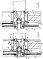
- Figures 1 and 1a are respective horizontal cross-sectional views showing possible combinations of section members specifically designed for restraining a glass panel or plate, on a so-called blind panel, and a box-like glass panel on a window opening;
- Figure 2 shows, by a vertical cross-sectional view, the same combination of section members and fixtures;
- Figure 3 is a further vertical cross-sectional view illustrating a like section member combination, provided with thermal cut characteristics, and further showing fixtures therefor, for restraining a box-like glass panel provided with an inner glass plate of less size;
- Figures 4 and 5 are respective horizontal cross-sectional views illustrating combinations of section members for respectively restraining two glass plates with a back blind panel and two box-like glass panels;
- Figures 6 and 7 are respective vertical cross-sectional views illustrating other combinations of section members and fixtures for restraining box-like glass panels constructed by using structural sealing materials and with different width gaps;
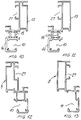
- Figures 8 and 9 illustrate two further section members which can be used as framing uprights;
- Figures 10 to 13 illustrate further section members provided for cooperating with the above mentioned upright section members;
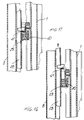
- Figures 14 and 15 illustrate a locking device for quick locking a window wing;
and - Figures 16 and 17 illustrate a possible operation of the locking device shown in figures 14 and 15.
- With reference to the figures of the accompanying drawings, the section member and fixture assembly for making continuous building facades according to the present invention comprises a
hollow section member 1, having preferably a square cross-section and provided, on a side thereof, with mushroom longitudinal ridges which define twoperimetrical seats 2, as well as a pair of contoured legs which define twoside restraing seats 3 and 3' and afront restraining seat 4. - This section member can be used as an upright and cross-section member and it can also be formed by the upright section member 1' shown in figure 8 which has contoured legs of greater extension.
- With the above mentioned section member, a
further section member 5, for restraining aglass plate 6 on ablind panel 7, and afurther section member 8 for restraining a box-like glass panel 9 cooperate, said box-like glass panel being provided for forming fixed glass panels and for defining window openings. - The cooperating section members, are substantially provided, respectively, with a reduced width
longitudinal seat 10 for restraining a single glass plate, and with a further seat, having a greater width, indicated at thereference number 11, for restraining or housing the box-like glass panel. - It should moreover be pointed out that, as the mentioned box-like glass panel is provided with a smaller size inner glass plate 9', then
further section members longitudinal seat 10, of reduced width, is formed by asecond section member 14 restrained to said section members by means ofpolyamide interconnecting elements 15, preferably of double-T shape. - The
section member 8 is specifically designed for operating as a window wing, and this wing will be formed by restraining in theseat 11 the box-like glass panel 8 through the interposition of suitable seals orgaskets section member 1 throughscrews 19 and on aninner abutment gasket 20 in turn restrained in its correspondingperimetrical seat 2 of saidsection member 1. - To the
section member 5, in turn, there is firmly connected ablind panel 7, by using asmall braket 21 affixed to the hollow body of thesection member 5 by means ofscrews 22. - Said
section member 5, moreover, is also provided, in addition to aninner gasket 16, with an outer perimetrical gasket orseal 23. - The
section member 5, as shown, is supported or bears on aninner abutment gasket 20, and is so designed as to define, between theglass plate 6 andblind panel 7, ananti-condensate gap 24. - In this connection it should be moreover pointed out that in the front seat of the
section member 1 there are engaged a pair ofgaskets 25, a further or second cooperatinggasket pair 26 being restrained in corresponding seats of thesection members - In the
side seats 27 of the latter, in particular, there is engaged aC section member 28, provided with outer lugs for firmly restraining this section member in said seats. - To said C section members a locking device can be vertically applied in order to lock and unlock the window wings, said locking device substantially comprising a
contoured body 29 which is provided with openopposite hollows 30 and 30' which are respectively upwardly and downwardly opened. - The mentioned body is restrained, by means of screws and a
small plate 40, in the side hollow 3 of thesection member 1, whereas, on thesection member 28 for locking the window wing, there is applied, at any desired height,alocking screw 41. - Thus, owing to the disclosed means, the mentioned section member for locking the window wing, will slide in contact with the hollow 29, so as to be automatically locked, at the set height, owing to the interference of the
screw 41 and thecontoured body 29. - As shown, there are moreover provided a contoured
small plate 31, of reduced width, and a furthersmall plate 32 which extends by a doubly bent portion 32' of less height. - These small plates are specifically designed for obtaining the vertical displacement of the C-
shape section member 28. - In particular, said small plates are provided with throughgoing holes and are affixed, by means of
screws 33, at a set position on said C section member. - Between the two glass plates of the box-like glass panel (as shown in figures 6 and 7) it is possible to locate a
spacer element 34, as well as a layer of astructural sealing material 35, and a not-structural sealing material 36, and, in order to provide a mechanically firm coupling of the outer glass plate of the box-like glass panel, a further suitably contouredfixture 37 can be provided, adapted to press on ahard rubber band 38. - From the above disclosure and the figures of the accompanying drawings, the great functionality and facility of use characterizing the section member and fixture assembly according to the present invention will be self evident.
Claims (7)
- A section member and fixture assembly, for making continuous building facades, comprising a hollow section member (1) provided, at one side thereof, with a pair of contoured lugs delimiting a front restraining seat (4) and at least a further hollow section member (5,8,12,13) cooperating with said hollow section member (1) and adapted to support a glass plate (6) or a box-like glass panel (9), said assembly further comprising quick intercoupling and locking means, finishing section members and sealing and/or abutment gaskets (16), (17), the said hollow section member (1) being provided as well with a pair of contoured legs defining two side restraining seats (3,3') facing a side seat (27) defined in said further hollow section member (5,8,12,13), in said side restraining seats (3,3') and in said side seat (27) there being adapted to be housed a device (28), (29) for locking and unlocking said further hollow section member (5,8,12,13) bearing said glass plate (6) or box-like glass panel (9), said hollow section member (1) being provided, laterally of said pair of contoured legs, with longitudinal ridges defining two perimetrical seats (2), said further hollow section member (5,8,12,13) engaging against a pair of gaskets (25) housed in said front restraining seat (4) and an inner abutment gasket (20) housed in one of said perimetrical seats (2), characterized in that said hollow section member (1) is adapted to operate both as an upright and as a crossmember, in that said locking device is vertically applied to C-shape section members (28) engaged in said seats (27), said device including a contoured body (29) provided with opposite hollow (30,30') respectively upwardly and downwardly opened, said body being locked, by means of screws and a plate (40) in said side seat (3,3') of said upright section member (1), whereas, on the section member (28) for locking said wing, there is applied a locking screw (41), and that said assembly further comprises a contoured plate (31) of reduced width and a further plate (32) extending with a double bent portion (32'), of less height than the bend portion (32), said plates (31,32) being provided with throughgoing holes and being locked to said C-shape section member (28) by screws (33) or the like.
- A section member and fixture assembly, according to Claim 1, characterized in that said at least a further hollow section member (5,8,12,13) comprises a first section member (15) adapted to affix a glass plate (6) on a blind panel (7) and a second section member for restraining a box-like glass panel (9) provided at window openings, said section members (5,9) being respectively provided with a longitudinal seat (10) of reduced width for restraining a single glass panel (6) and a greater width seat adapted to house said box-like panel (9).
- A section member and fixture assembly according to the preceding claims, characterized in that it further comprises two section members (12,13) similar to said further hollow section members (5,8) in which said reduced width longitudinal seat (10) is defined by a further section member (14) connected to said section members (12,13) by double T shaped polyamide interconnecting elements (15).
- A section member and fixture assembly, according to one or more of the preceding claims, characterized in that said further hollow section member (8) housing said box-like glass panel (9) operates as a wing and restrain said box-like glass panel through the interposition of gaskets (17,23), said section member (8) bearing, in its closure condition, on a contoured resilient fixture (18) fixed to said upright hollow section member (1) by screws, and on said inner abutment gasket (20) engaged in the corresponding perimetrical seat (2) provided on said upright section member (1).
- A section member and fixture assembly, according to one or more of the preceding claims, characterized in that it further includes a bracket (21) for anchoring that further hollow section member (5) to a blind panel (7) the bracket (21) being affixed to the hollow body (5) by screws (22), in that the further hollow section member (5) bears, in addition to an inner gasket (16), a perimetrical outer gasket (23), said further hollow section member (5) bearing moreover on said inner abutment gasket (20) and being so designed as to define, between said glass plate (6) and blind panel (7) an anticondensate gap (24).
- A section member and fixture assembly, according to one or more of the preceding claims, characterized in that it further comprises a first pair of gaskets (25) which are engaged in the front seat (4) of said upright section member (1) and a second pair of gaskets (26) engaged in corresponding seats of the further hollow section members (5,8,12,13) for restraining said glass panel (6) or box-like glass panel (9).
- A section member and fixture assembly, according to one or more of the preceding claims, characterized in that it further comprises spacer elements (34) to be arranged between the two glass panels of a box-like glass panel (9) through the interposition of a structural sealing layer (35) and a not structural sealing layer (36) as well as a fixture pressing on a hard rubber band (38).
Applications Claiming Priority (2)
| Application Number | Priority Date | Filing Date | Title |
|---|---|---|---|
| ITMI910665A IT1252611B (en) | 1991-03-13 | 1991-03-13 | SERIES OF PROFILES, AND RELATED ACCESSORIES, SUITABLE TO ALLOW THE CONSTRUCTION OF CONTINUOUS FACADES OF BUILDINGS |
| ITMI910665 | 1991-03-13 |
Publications (2)
| Publication Number | Publication Date |
|---|---|
| EP0506622A1 EP0506622A1 (en) | 1992-09-30 |
| EP0506622B1 true EP0506622B1 (en) | 1996-02-07 |
Family
ID=11359013
Family Applications (1)
| Application Number | Title | Priority Date | Filing Date |
|---|---|---|---|
| EP92830109A Expired - Lifetime EP0506622B1 (en) | 1991-03-13 | 1992-03-10 | Section member and fixture assembly for making continuous building faces |
Country Status (7)
| Country | Link |
|---|---|
| EP (1) | EP0506622B1 (en) |
| AT (1) | ATE134012T1 (en) |
| DE (1) | DE69208128D1 (en) |
| ES (1) | ES2084982T3 (en) |
| GR (1) | GR3019863T3 (en) |
| IL (1) | IL101208A (en) |
| IT (1) | IT1252611B (en) |
Families Citing this family (3)
| Publication number | Priority date | Publication date | Assignee | Title |
|---|---|---|---|---|
| IT1296953B1 (en) * | 1997-12-11 | 1999-08-03 | Hydro Aluminium Systems Spa | COMPLEX OF METAL PROFILES FOR THE MANUFACTURE OF CONTINUOUS FACADES OF BUILDINGS |
| GB2482902B (en) * | 2010-08-19 | 2016-02-03 | Don Reynolds Ltd | A curtain walling system |
| CN106639765A (en) * | 2016-08-31 | 2017-05-10 | 浙江建业幕墙装饰有限公司 | Three path sealed curtain wall top-hung window |
Family Cites Families (6)
| Publication number | Priority date | Publication date | Assignee | Title |
|---|---|---|---|---|
| DE3024402A1 (en) * | 1980-06-28 | 1982-01-21 | Alb. Klein Gmbh & Co Kg, 5241 Niederfischbach | LOW-ARM AND MASTER-ARM MANIPULATOR |
| DE3903117A1 (en) * | 1989-02-02 | 1990-08-09 | Otto Wolff Kunststoffvertrieb | Retaining profile for a panel |
| FR2652863B1 (en) * | 1989-10-05 | 1992-03-06 | Aubin Philippe | DEVICE FOR FIXING A FLAT SURFACE, ESPECIALLY GLASS, ON A SUPPORT FRAME. |
| IT1248421B (en) * | 1989-12-06 | 1995-01-16 | Metra Spa | CONTINUOUS FACADE FOR BUILDINGS AND SIMILAR, MADE WITH ALUMINUM PROFILES. |
| DE9014754U1 (en) * | 1990-04-14 | 1991-01-03 | W. Hartmann & Co (Gmbh & Co), 2000 Hamburg | Anchoring device for optically frameless glazing |
| US5076035A (en) * | 1990-09-26 | 1991-12-31 | Wright John T | Channel assembly for mounting building panels |
-
1991
- 1991-03-13 IT ITMI910665A patent/IT1252611B/en active IP Right Grant
-
1992
- 1992-03-10 ES ES92830109T patent/ES2084982T3/en not_active Expired - Lifetime
- 1992-03-10 AT AT92830109T patent/ATE134012T1/en not_active IP Right Cessation
- 1992-03-10 DE DE69208128T patent/DE69208128D1/en not_active Expired - Lifetime
- 1992-03-10 EP EP92830109A patent/EP0506622B1/en not_active Expired - Lifetime
- 1992-03-12 IL IL10120892A patent/IL101208A/en not_active IP Right Cessation
-
1996
- 1996-05-07 GR GR960401249T patent/GR3019863T3/en unknown
Also Published As
| Publication number | Publication date |
|---|---|
| DE69208128D1 (en) | 1996-03-21 |
| EP0506622A1 (en) | 1992-09-30 |
| ITMI910665A0 (en) | 1991-03-13 |
| GR3019863T3 (en) | 1996-08-31 |
| IL101208A (en) | 1994-08-26 |
| ATE134012T1 (en) | 1996-02-15 |
| IT1252611B (en) | 1995-06-19 |
| ITMI910665A1 (en) | 1992-09-13 |
| ES2084982T3 (en) | 1996-05-16 |
Similar Documents
| Publication | Publication Date | Title |
|---|---|---|
| US3696569A (en) | Demountable partition wall | |
| JP2829826B2 (en) | Curtain wall panel material mounting structure | |
| JPH09209658A (en) | Fitting structure of batten for frame member | |
| EP0506622B1 (en) | Section member and fixture assembly for making continuous building faces | |
| EP0496187B1 (en) | Section member assembly for making continuous building glazed walls | |
| EP0432105B1 (en) | Aluminium section member building continuous front | |
| JPH0497048A (en) | Mounting construction of facing panel | |
| EP0317689B1 (en) | Structurally cooperating section member assembly for making sliding shutter windows and fastenings in general | |
| JPH0648074Y2 (en) | Shoji panel mounting structure | |
| JPS6231582Y2 (en) | ||
| JPS5918076Y2 (en) | Screen grid with insect screen | |
| JPH0322411Y2 (en) | ||
| JP2832784B2 (en) | curtain wall | |
| JPS6123585Y2 (en) | ||
| US3040850A (en) | Window | |
| JPH0312886Y2 (en) | ||
| JPH0732845Y2 (en) | Windows | |
| JPH10148059A (en) | Exterior wall opening structure | |
| JPH0321422Y2 (en) | ||
| JPH0425511Y2 (en) | ||
| JPH0232783Y2 (en) | ||
| JPS5817915Y2 (en) | Sealed structure of shoji butt part | |
| KR200149544Y1 (en) | Assembly structure of the door | |
| JPH041269Y2 (en) | ||
| JPH0750544Y2 (en) | Area lattice locking device |
Legal Events
| Date | Code | Title | Description |
|---|---|---|---|
| PUAI | Public reference made under article 153(3) epc to a published international application that has entered the european phase |
Free format text: ORIGINAL CODE: 0009012 |
|
| AK | Designated contracting states |
Kind code of ref document: A1 Designated state(s): AT BE CH DE DK ES FR GB GR IT LI LU MC NL PT SE |
|
| DX | Miscellaneous (deleted) | ||
| 17P | Request for examination filed |
Effective date: 19921223 |
|
| 17Q | First examination report despatched |
Effective date: 19931227 |
|
| GRAA | (expected) grant |
Free format text: ORIGINAL CODE: 0009210 |
|
| AK | Designated contracting states |
Kind code of ref document: B1 Designated state(s): AT BE CH DE DK ES FR GB GR IT LI LU MC NL PT SE |
|
| PG25 | Lapsed in a contracting state [announced via postgrant information from national office to epo] |
Ref country code: NL Free format text: LAPSE BECAUSE OF FAILURE TO SUBMIT A TRANSLATION OF THE DESCRIPTION OR TO PAY THE FEE WITHIN THE PRESCRIBED TIME-LIMIT Effective date: 19960207 Ref country code: LI Free format text: LAPSE BECAUSE OF FAILURE TO SUBMIT A TRANSLATION OF THE DESCRIPTION OR TO PAY THE FEE WITHIN THE PRESCRIBED TIME-LIMIT Effective date: 19960207 Ref country code: DK Effective date: 19960207 Ref country code: CH Free format text: LAPSE BECAUSE OF FAILURE TO SUBMIT A TRANSLATION OF THE DESCRIPTION OR TO PAY THE FEE WITHIN THE PRESCRIBED TIME-LIMIT Effective date: 19960207 Ref country code: AT Effective date: 19960207 |
|
| REF | Corresponds to: |
Ref document number: 134012 Country of ref document: AT Date of ref document: 19960215 Kind code of ref document: T |
|
| ITF | It: translation for a ep patent filed | ||
| PG25 | Lapsed in a contracting state [announced via postgrant information from national office to epo] |
Ref country code: MC Effective date: 19960310 |
|
| REF | Corresponds to: |
Ref document number: 69208128 Country of ref document: DE Date of ref document: 19960321 |
|
| PG25 | Lapsed in a contracting state [announced via postgrant information from national office to epo] |
Ref country code: LU Free format text: LAPSE BECAUSE OF NON-PAYMENT OF DUE FEES Effective date: 19960331 |
|
| PG25 | Lapsed in a contracting state [announced via postgrant information from national office to epo] |
Ref country code: SE Effective date: 19960507 Ref country code: GB Effective date: 19960507 |
|
| PG25 | Lapsed in a contracting state [announced via postgrant information from national office to epo] |
Ref country code: DE Effective date: 19960508 |
|
| REG | Reference to a national code |
Ref country code: ES Ref legal event code: FG2A Ref document number: 2084982 Country of ref document: ES Kind code of ref document: T3 |
|
| ET | Fr: translation filed | ||
| SC4A | Pt: translation is available |
Free format text: 960207 AVAILABILITY OF NATIONAL TRANSLATION |
|
| NLV1 | Nl: lapsed or annulled due to failure to fulfill the requirements of art. 29p and 29m of the patents act | ||
| REG | Reference to a national code |
Ref country code: GR Ref legal event code: FG4A Free format text: 3019863 |
|
| REG | Reference to a national code |
Ref country code: CH Ref legal event code: PL |
|
| PLBE | No opposition filed within time limit |
Free format text: ORIGINAL CODE: 0009261 |
|
| GBPC | Gb: european patent ceased through non-payment of renewal fee |
Effective date: 19960507 |
|
| 26N | No opposition filed | ||
| PGFP | Annual fee paid to national office [announced via postgrant information from national office to epo] |
Ref country code: ES Payment date: 19990308 Year of fee payment: 8 Ref country code: BE Payment date: 19990308 Year of fee payment: 8 |
|
| PGFP | Annual fee paid to national office [announced via postgrant information from national office to epo] |
Ref country code: PT Payment date: 19990310 Year of fee payment: 8 |
|
| PGFP | Annual fee paid to national office [announced via postgrant information from national office to epo] |
Ref country code: GR Payment date: 19990329 Year of fee payment: 8 |
|
| PGFP | Annual fee paid to national office [announced via postgrant information from national office to epo] |
Ref country code: FR Payment date: 19990330 Year of fee payment: 8 |
|
| PG25 | Lapsed in a contracting state [announced via postgrant information from national office to epo] |
Ref country code: ES Free format text: LAPSE BECAUSE OF NON-PAYMENT OF DUE FEES Effective date: 20000311 |
|
| PG25 | Lapsed in a contracting state [announced via postgrant information from national office to epo] |
Ref country code: GR Free format text: LAPSE BECAUSE OF NON-PAYMENT OF DUE FEES Effective date: 20000331 Ref country code: BE Free format text: LAPSE BECAUSE OF NON-PAYMENT OF DUE FEES Effective date: 20000331 |
|
| BERE | Be: lapsed |
Owner name: METALLURGICA TRAFILATI ALLUMINIO S.P.A. METRA Effective date: 20000331 |
|
| PG25 | Lapsed in a contracting state [announced via postgrant information from national office to epo] |
Ref country code: PT Free format text: LAPSE BECAUSE OF NON-PAYMENT OF DUE FEES Effective date: 20000930 |
|
| PG25 | Lapsed in a contracting state [announced via postgrant information from national office to epo] |
Ref country code: FR Free format text: LAPSE BECAUSE OF NON-PAYMENT OF DUE FEES Effective date: 20001130 |
|
| REG | Reference to a national code |
Ref country code: FR Ref legal event code: ST |
|
| REG | Reference to a national code |
Ref country code: PT Ref legal event code: MM4A Free format text: LAPSE DUE TO NON-PAYMENT OF FEES Effective date: 20000930 |
|
| REG | Reference to a national code |
Ref country code: ES Ref legal event code: FD2A Effective date: 20011010 |
|
| PG25 | Lapsed in a contracting state [announced via postgrant information from national office to epo] |
Ref country code: IT Free format text: LAPSE BECAUSE OF NON-PAYMENT OF DUE FEES;WARNING: LAPSES OF ITALIAN PATENTS WITH EFFECTIVE DATE BEFORE 2007 MAY HAVE OCCURRED AT ANY TIME BEFORE 2007. THE CORRECT EFFECTIVE DATE MAY BE DIFFERENT FROM THE ONE RECORDED. Effective date: 20050310 |