EP0506547A1 - Vorrichtung zur automatischen Regelung eines Signalpegels - Google Patents
Vorrichtung zur automatischen Regelung eines Signalpegels Download PDFInfo
- Publication number
- EP0506547A1 EP0506547A1 EP92400796A EP92400796A EP0506547A1 EP 0506547 A1 EP0506547 A1 EP 0506547A1 EP 92400796 A EP92400796 A EP 92400796A EP 92400796 A EP92400796 A EP 92400796A EP 0506547 A1 EP0506547 A1 EP 0506547A1
- Authority
- EP
- European Patent Office
- Prior art keywords
- level
- control
- loop
- signal
- adjustment circuit
- Prior art date
- Legal status (The legal status is an assumption and is not a legal conclusion. Google has not performed a legal analysis and makes no representation as to the accuracy of the status listed.)
- Granted
Links
Images


Classifications
-
- H—ELECTRICITY
- H03—ELECTRONIC CIRCUITRY
- H03G—CONTROL OF AMPLIFICATION
- H03G3/00—Gain control in amplifiers or frequency changers
- H03G3/20—Automatic control
- H03G3/30—Automatic control in amplifiers having semiconductor devices
- H03G3/3005—Automatic control in amplifiers having semiconductor devices in amplifiers suitable for low-frequencies, e.g. audio amplifiers
- H03G3/301—Automatic control in amplifiers having semiconductor devices in amplifiers suitable for low-frequencies, e.g. audio amplifiers the gain being continuously variable
- H03G3/3015—Automatic control in amplifiers having semiconductor devices in amplifiers suitable for low-frequencies, e.g. audio amplifiers the gain being continuously variable using diodes or transistors
-
- H—ELECTRICITY
- H03—ELECTRONIC CIRCUITRY
- H03G—CONTROL OF AMPLIFICATION
- H03G1/00—Details of arrangements for controlling amplification
- H03G1/0005—Circuits characterised by the type of controlling devices operated by a controlling current or voltage signal
- H03G1/0035—Circuits characterised by the type of controlling devices operated by a controlling current or voltage signal using continuously variable impedance elements
- H03G1/007—Circuits characterised by the type of controlling devices operated by a controlling current or voltage signal using continuously variable impedance elements using field-effect transistors [FET]
-
- H—ELECTRICITY
- H03—ELECTRONIC CIRCUITRY
- H03G—CONTROL OF AMPLIFICATION
- H03G1/00—Details of arrangements for controlling amplification
- H03G1/0005—Circuits characterised by the type of controlling devices operated by a controlling current or voltage signal
- H03G1/0088—Circuits characterised by the type of controlling devices operated by a controlling current or voltage signal using discontinuously variable devices, e.g. switch-operated
-
- H—ELECTRICITY
- H03—ELECTRONIC CIRCUITRY
- H03G—CONTROL OF AMPLIFICATION
- H03G3/00—Gain control in amplifiers or frequency changers
- H03G3/001—Digital control of analog signals
Definitions
- the present invention relates to a device for automatically adjusting the level of a so-called incident signal received by this device, providing in response a so-called output signal of substantially equal level, whatever the variations of the incident signal, at a constant level. possibly selectable among "n" possible levels.
- the reference 1 designates an amplifier, called an output, the level of the output signal of which, S, is to be adjusted automatically
- reference 2 designates an attenuator which receives the incident signal, I, supplies in response the input signal of the output amplifier 1, and is further controlled by a so-called AC servo control developed by a servo loop 3, so as to keep the level of the input signal of the amplifier 1 constant whatever the level of the incident signal I.
- This control loop itself comprises a comparator, amplifier 4 which compares, with respect to a reference level VREF, the level of the output signal from this attenuator, after rectification in a rectifier 5 and filtering in a low-pass filter 6.
- the output level of the amplifier 1 is also selectable from "n" possible levels, which is in this case obtained by a corresponding commando CE of the gain of the amplifier 1, called the external commando.
- this control loop is also not effective against possible overvoltages appearing in the alternations of the incident signal not taken into account by this rectifier, in particular when the device is put into service or at frequency changes occurring in said incident signal.
- the subject of the present invention is an automatic level adjustment device for a so-called incident signal received by this device, providing in response a so-called output signal of substantially equal level, whatever the variations of the incident signal, at a constant level.
- a level adjustment circuit provided with a gain control loop which generates a control depending on the level of the output signal and optionally further controlled by said external gain control to provide, in response to said incident signal, said output signal, essentially characterized in that said gain control loop which generates a function control the level of the output signal being said first loop, said level adjustment circuit is further provided with a second loop the gain control which develops a command as a function of the instantaneous amplitude of the output signal.
- FIG. 2 The block diagram of an automatic adjustment device according to the invention illustrated in FIG. 2 includes by way of example an attenuator, marked here 20 and receiving the incident signal I, and a so-called output amplifier, marked 100, and providing , in response to the signal from this attenuator, said output signal.
- an attenuator marked here 20 and receiving the incident signal I
- an output amplifier marked 100
- level adjustment circuit which depending on the envisaged application, could possibly be reduced to only one of these elements.
- This level adjustment circuit is controlled on the one hand by a gain control command, CA, in order to provide an output signal S of substantially constant level, whatever the variations in level of the incident signal, and d on the other hand by an external gain control, CE, in order to select this level among "n" possible levels.
- CA gain control command
- CE external gain control
- the servo loop identified here 30, providing said servo control, comprises, in order, a rectifier 50, a low-pass filter 60, and a comparator-amplifier 40 which compares the signal level obtained at the output of the low-pass filter 60 at a fixed reference level VREF.
- the servo loop 30 is in this case supplied by the output signal S which is applied in this loop to an amplifier 101, called a loop amplifier, the gain of which is controlled, with that of the level control circuit 200, by said external command CE, so that the gains from the level control circuit and the loop amplifier are substantially independent of the level selected for the output signal.
- the block diagram of FIG. 2 includes a second gain control loop, 16, of the level adjustment circuit as a function of the instantaneous amplitude of the output signal, making it possible to avoid the drawbacks due to the reaction time of the control loop 30 and / or not taking into account one of the alternations of the incident signal in this first control loop when the rectifier used in this loop is a single-alternation rectifier.
- This second control loop 16 develops a gain control command, CA ′, of the level adjustment circuit 200, in this case from the signal from the amplifier 101 but not rectified, so as to take account of , for this second control, possible overvoltages present in the incident signal, in particular those of the half-waves not taken into account by the rectifier 50 when the latter is a single half-wave rectifier.
- This second control loop may comprise, as a function of the amplitude necessary for the gain control of the adjustment circuit, means 14 for amplitude adaptation.
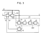
- FIG. 3 illustrates an advantageous mode of defining the gain of the level adjustment circuit, by controlling the gain of the output amplifier 100 by means of said external control CE, and by controlling the attenuation provided by the attenuator 20 by means of said control loop 30.
- the attenuator 20 is provided with a second control input, receiving in this case the control command CA ′.
- the elements M1 and M2 are in this case field effect transistors, the grid of which receives the signal from the comparator 40 and the signal from the amplitude adaptation means 14, respectively.
- the conduction of the transistor M2 is such that the weakening of the attenuator 20 is modified so as to reduce this instantaneous amplitude.
- the high-pass filter in this case constituted by a capacitor CI, inserted between the output of the amplifier 100 and the input of the amplifier 101 has the role of eliminating the voltage of " offset "of amplifier 100.
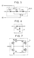
- FIG. 5 represents a diagram of possible embodiment of such controllable feedback resistors R1 and R3 simultaneously so as to permanently keep the gain product of amplifiers 100 and 101 substantially independent of the level selected for the output signal,
- This diagram consists of an association of a certain number of fixed resistors, in this case three resistors, R10, R11, R12, according to a configuration modifiable by action on a certain number of controllable switches, in this case two switches I1 , I2 controlled respectively by binary signals CE1, CE2 so that when these two switches are open, these three resistors are associated in series, hence for the whole a resistance value Rmax, only when one of these two switches is open and the other closed, two of these three resistors in series are short-circuited, the whole being equivalent to a single resistance, hence for the whole an average resistance value Rmoy, and that when these two switches are closed, these three resistors are associated in parallel, hence for the whole a minimum resistance value Rmin.
- the amplitude adaptation means 14 shown in the figure 6 comprise a voltage divider formed by means of two resistors R15, R13.
- the amplitude adaptation means 14 shown in FIG. 7 comprise a threshold device formed by association of two assemblies each formed by association in series of two field effect transistors of opposite types, respectively M3, M4 and M5, M6 and known to each perform a function of inverting a signal applied to its input.
- the input of the first assembly M3, M4 constitutes the input of these amplitude adaptation means
- the output of the first assembly is applied to the input of the second assembly M5, M6
- the output of the second assembly constitutes the output of these amplitude adaptation means.
- the supply voltages of transistors of the same type are also identical, one of these supply voltages being marked VDD and the other being in this case the reference voltage shown here by the ground, and transistors of opposite types have symmetrical characteristics.
- one or other of the transistors M3 and M4 conducts, which results in the conduction of one or more the other respectively of the transistors M6 and M5 in which case the signal obtained at the output of these amplitude adaptation means is a function of the input signal and the conduction characteristics of the transistors used.
Landscapes
- Engineering & Computer Science (AREA)
- Multimedia (AREA)
- Control Of Amplification And Gain Control (AREA)
- Input Circuits Of Receivers And Coupling Of Receivers And Audio Equipment (AREA)
- Details Of Television Scanning (AREA)
- Circuits Of Receivers In General (AREA)
- Stereophonic System (AREA)
- Reverberation, Karaoke And Other Acoustics (AREA)
Applications Claiming Priority (2)
| Application Number | Priority Date | Filing Date | Title |
|---|---|---|---|
| FR9103645A FR2674707B1 (fr) | 1991-03-26 | 1991-03-26 | Dispositif de reglage automatique de niveau d'un signal. |
| FR9103645 | 1991-03-26 |
Publications (2)
| Publication Number | Publication Date |
|---|---|
| EP0506547A1 true EP0506547A1 (de) | 1992-09-30 |
| EP0506547B1 EP0506547B1 (de) | 1995-05-10 |
Family
ID=9411133
Family Applications (1)
| Application Number | Title | Priority Date | Filing Date |
|---|---|---|---|
| EP92400796A Expired - Lifetime EP0506547B1 (de) | 1991-03-26 | 1992-03-24 | Vorrichtung zur automatischen Regelung eines Signalpegels |
Country Status (5)
| Country | Link |
|---|---|
| EP (1) | EP0506547B1 (de) |
| AT (1) | ATE122509T1 (de) |
| DE (1) | DE69202382T2 (de) |
| ES (1) | ES2072722T3 (de) |
| FR (1) | FR2674707B1 (de) |
Cited By (1)
| Publication number | Priority date | Publication date | Assignee | Title |
|---|---|---|---|---|
| WO2000079748A1 (en) * | 1999-06-23 | 2000-12-28 | At & T Wireless Services, Inc. | Automatic gain control for ofdm receiver |
Citations (3)
| Publication number | Priority date | Publication date | Assignee | Title |
|---|---|---|---|---|
| GB2097619A (en) * | 1980-07-31 | 1982-11-03 | Min Mart V | Stage converter of electric signals |
| US4531229A (en) * | 1982-10-22 | 1985-07-23 | Coulter Associates, Inc. | Method and apparatus for improving binaural hearing |
| US4771472A (en) * | 1987-04-14 | 1988-09-13 | Hughes Aircraft Company | Method and apparatus for improving voice intelligibility in high noise environments |
Family Cites Families (1)
| Publication number | Priority date | Publication date | Assignee | Title |
|---|---|---|---|---|
| JPS5937716A (ja) * | 1982-08-26 | 1984-03-01 | Seiko Instr & Electronics Ltd | 自動利得制御回路 |
-
1991
- 1991-03-26 FR FR9103645A patent/FR2674707B1/fr not_active Expired - Fee Related
-
1992
- 1992-03-24 EP EP92400796A patent/EP0506547B1/de not_active Expired - Lifetime
- 1992-03-24 ES ES92400796T patent/ES2072722T3/es not_active Expired - Lifetime
- 1992-03-24 DE DE69202382T patent/DE69202382T2/de not_active Expired - Fee Related
- 1992-03-24 AT AT92400796T patent/ATE122509T1/de not_active IP Right Cessation
Patent Citations (3)
| Publication number | Priority date | Publication date | Assignee | Title |
|---|---|---|---|---|
| GB2097619A (en) * | 1980-07-31 | 1982-11-03 | Min Mart V | Stage converter of electric signals |
| US4531229A (en) * | 1982-10-22 | 1985-07-23 | Coulter Associates, Inc. | Method and apparatus for improving binaural hearing |
| US4771472A (en) * | 1987-04-14 | 1988-09-13 | Hughes Aircraft Company | Method and apparatus for improving voice intelligibility in high noise environments |
Non-Patent Citations (1)
| Title |
|---|
| PATENT ABSTRACTS OF JAPAN vol. 8, no. 127 (E-250)(1564) 14 Juin 1984 & JP-A-59 037 716 ( SEIKO DENSHI KOGYO ) * |
Cited By (4)
| Publication number | Priority date | Publication date | Assignee | Title |
|---|---|---|---|---|
| WO2000079748A1 (en) * | 1999-06-23 | 2000-12-28 | At & T Wireless Services, Inc. | Automatic gain control for ofdm receiver |
| US6363127B1 (en) | 1999-06-23 | 2002-03-26 | At&T Wireless Services, Inc. | Automatic gain control methods and apparatus suitable for use in OFDM receivers |
| US6574292B2 (en) | 1999-06-23 | 2003-06-03 | At&T Wireless Services, Inc. | Automatic gain control methods and apparatus suitable for use in OFDM receivers |
| US7065165B2 (en) | 1999-06-23 | 2006-06-20 | Cingular Wireless Ii, Llc | Automatic gain control methods and apparatus suitable for use in OFDM receivers |
Also Published As
| Publication number | Publication date |
|---|---|
| ES2072722T3 (es) | 1995-07-16 |
| DE69202382T2 (de) | 1995-09-14 |
| FR2674707B1 (fr) | 1993-06-04 |
| ATE122509T1 (de) | 1995-05-15 |
| FR2674707A1 (fr) | 1992-10-02 |
| EP0506547B1 (de) | 1995-05-10 |
| DE69202382D1 (de) | 1995-06-14 |
Similar Documents
| Publication | Publication Date | Title |
|---|---|---|
| EP0326489B1 (de) | Regulierungssystem des Arbeitspunktes einer Gleichstromversorgung | |
| FR2471709A1 (fr) | Alimentation de ligne telephonique | |
| FR2478904A1 (fr) | Circuit de commande de gain | |
| FR2652697A1 (fr) | Extracteur de donnees numeriques dans un signal video. | |
| EP0278193B1 (de) | Schaltung zum Messen des die Primärwicklung des Ausgangstransformators eines Wechselrichters durch fliessenden Gleichstromanteiles | |
| FR2554989A1 (fr) | Regulateur de tension serie | |
| FR2473234A1 (fr) | Circuit a impedance electriquement variable et a compensation par reaction | |
| EP0506547B1 (de) | Vorrichtung zur automatischen Regelung eines Signalpegels | |
| FR2636740A1 (fr) | Detecteur d'enveloppe logarithmique de signal analogique | |
| EP1010048B1 (de) | Spannungsregelungsschaltung zur unterdrückung des latch-up phänomens | |
| FR2728074A1 (fr) | Procede de detection de la puissance electrique absorbee par une charge, du type alimentation non lineaire, et son application a la commande d'appareils auxiliaires | |
| FR2674706A1 (fr) | Dispositif de reglage automatique de niveau d'un signal. | |
| EP0042641B1 (de) | Frequenzdemodulator mit einer Verzögerungsschaltung, wobei die Verzögerung von der empfangenen Frequenz abhängig ist | |
| FR2645373A1 (fr) | Procede et dispositif de reduction du bruit sur un signal codable a plusieurs niveaux predetermines | |
| FR2674705A1 (fr) | Dispositif amplificateur video. | |
| CA1147027A (fr) | Circuit filtre passe-bas a tres basse frequence | |
| FR2685583A1 (fr) | Synthetiseur de frequences multibande. | |
| EP0868030B1 (de) | Phasenregelkreis mit Phasenregelhilfsschaltung | |
| FR2626420A1 (fr) | Dispositif d'asservissement en frequence d'un oscillateur | |
| EP0021867A1 (de) | Gegen Schwankungen der Eingangsspannung und der Ausgangsleistung geregelte Zerhacker-Spannungsversorgungsschaltung, insbesondere für Fernsehempfänger | |
| EP0046421A1 (de) | Empfänger für Signalübertragungssystem mittels elektromagnetischer, insbesondere infraroter Strahlung | |
| FR2545304A1 (fr) | Dispositif d'extraction des impulsions de synchronisation d'un signal video et de generation de signaux d'alignement | |
| FR2626689A1 (fr) | Systeme de regulation du point de fonctionnement d'une alimentation a courant continu | |
| FR2604583A1 (fr) | Dispositif de conditionnement de signaux video de transmission d'images | |
| CH691203A5 (fr) | Circuit de régulation de tension destiné à supprimer un phénomène dit "latch-up". |
Legal Events
| Date | Code | Title | Description |
|---|---|---|---|
| PUAI | Public reference made under article 153(3) epc to a published international application that has entered the european phase |
Free format text: ORIGINAL CODE: 0009012 |
|
| AK | Designated contracting states |
Kind code of ref document: A1 Designated state(s): AT BE CH DE ES FR GB IT LI NL SE |
|
| 17P | Request for examination filed |
Effective date: 19930322 |
|
| 17Q | First examination report despatched |
Effective date: 19940613 |
|
| GRAA | (expected) grant |
Free format text: ORIGINAL CODE: 0009210 |
|
| AK | Designated contracting states |
Kind code of ref document: B1 Designated state(s): AT BE CH DE ES FR GB IT LI NL SE |
|
| REF | Corresponds to: |
Ref document number: 122509 Country of ref document: AT Date of ref document: 19950515 Kind code of ref document: T |
|
| REF | Corresponds to: |
Ref document number: 69202382 Country of ref document: DE Date of ref document: 19950614 |
|
| ITF | It: translation for a ep patent filed | ||
| REG | Reference to a national code |
Ref country code: ES Ref legal event code: FG2A Ref document number: 2072722 Country of ref document: ES Kind code of ref document: T3 |
|
| GBT | Gb: translation of ep patent filed (gb section 77(6)(a)/1977) |
Effective date: 19950714 |
|
| PLBE | No opposition filed within time limit |
Free format text: ORIGINAL CODE: 0009261 |
|
| STAA | Information on the status of an ep patent application or granted ep patent |
Free format text: STATUS: NO OPPOSITION FILED WITHIN TIME LIMIT |
|
| 26N | No opposition filed | ||
| REG | Reference to a national code |
Ref country code: GB Ref legal event code: IF02 |
|
| PGFP | Annual fee paid to national office [announced via postgrant information from national office to epo] |
Ref country code: NL Payment date: 20040229 Year of fee payment: 13 |
|
| PGFP | Annual fee paid to national office [announced via postgrant information from national office to epo] |
Ref country code: AT Payment date: 20040303 Year of fee payment: 13 |
|
| PGFP | Annual fee paid to national office [announced via postgrant information from national office to epo] |
Ref country code: SE Payment date: 20040319 Year of fee payment: 13 |
|
| PGFP | Annual fee paid to national office [announced via postgrant information from national office to epo] |
Ref country code: CH Payment date: 20040322 Year of fee payment: 13 |
|
| PGFP | Annual fee paid to national office [announced via postgrant information from national office to epo] |
Ref country code: BE Payment date: 20040511 Year of fee payment: 13 |
|
| PG25 | Lapsed in a contracting state [announced via postgrant information from national office to epo] |
Ref country code: AT Free format text: LAPSE BECAUSE OF NON-PAYMENT OF DUE FEES Effective date: 20050324 |
|
| PG25 | Lapsed in a contracting state [announced via postgrant information from national office to epo] |
Ref country code: SE Free format text: LAPSE BECAUSE OF NON-PAYMENT OF DUE FEES Effective date: 20050325 |
|
| PG25 | Lapsed in a contracting state [announced via postgrant information from national office to epo] |
Ref country code: LI Free format text: LAPSE BECAUSE OF NON-PAYMENT OF DUE FEES Effective date: 20050331 Ref country code: CH Free format text: LAPSE BECAUSE OF NON-PAYMENT OF DUE FEES Effective date: 20050331 Ref country code: BE Free format text: LAPSE BECAUSE OF NON-PAYMENT OF DUE FEES Effective date: 20050331 |
|
| BERE | Be: lapsed |
Owner name: *ALCATEL CIT Effective date: 20050331 |
|
| PG25 | Lapsed in a contracting state [announced via postgrant information from national office to epo] |
Ref country code: NL Free format text: LAPSE BECAUSE OF NON-PAYMENT OF DUE FEES Effective date: 20051001 |
|
| EUG | Se: european patent has lapsed | ||
| REG | Reference to a national code |
Ref country code: CH Ref legal event code: PL |
|
| NLV4 | Nl: lapsed or anulled due to non-payment of the annual fee |
Effective date: 20051001 |
|
| PGFP | Annual fee paid to national office [announced via postgrant information from national office to epo] |
Ref country code: ES Payment date: 20060327 Year of fee payment: 15 |
|
| PGFP | Annual fee paid to national office [announced via postgrant information from national office to epo] |
Ref country code: GB Payment date: 20060329 Year of fee payment: 15 |
|
| PGFP | Annual fee paid to national office [announced via postgrant information from national office to epo] |
Ref country code: DE Payment date: 20070430 Year of fee payment: 16 |
|
| GBPC | Gb: european patent ceased through non-payment of renewal fee |
Effective date: 20070324 |
|
| BERE | Be: lapsed |
Owner name: *ALCATEL CIT Effective date: 20050331 |
|
| PGFP | Annual fee paid to national office [announced via postgrant information from national office to epo] |
Ref country code: IT Payment date: 20070608 Year of fee payment: 16 |
|
| PG25 | Lapsed in a contracting state [announced via postgrant information from national office to epo] |
Ref country code: GB Free format text: LAPSE BECAUSE OF NON-PAYMENT OF DUE FEES Effective date: 20070324 |
|
| PGFP | Annual fee paid to national office [announced via postgrant information from national office to epo] |
Ref country code: FR Payment date: 20070319 Year of fee payment: 16 |
|
| REG | Reference to a national code |
Ref country code: ES Ref legal event code: FD2A Effective date: 20070326 |
|
| PG25 | Lapsed in a contracting state [announced via postgrant information from national office to epo] |
Ref country code: ES Free format text: LAPSE BECAUSE OF NON-PAYMENT OF DUE FEES Effective date: 20070326 |
|
| REG | Reference to a national code |
Ref country code: FR Ref legal event code: ST Effective date: 20081125 |
|
| PG25 | Lapsed in a contracting state [announced via postgrant information from national office to epo] |
Ref country code: DE Free format text: LAPSE BECAUSE OF NON-PAYMENT OF DUE FEES Effective date: 20081001 |
|
| PG25 | Lapsed in a contracting state [announced via postgrant information from national office to epo] |
Ref country code: FR Free format text: LAPSE BECAUSE OF NON-PAYMENT OF DUE FEES Effective date: 20080331 |
|
| PG25 | Lapsed in a contracting state [announced via postgrant information from national office to epo] |
Ref country code: IT Free format text: LAPSE BECAUSE OF NON-PAYMENT OF DUE FEES Effective date: 20080324 |