EP0506533A1 - Sawing apparatus - Google Patents
Sawing apparatus Download PDFInfo
- Publication number
- EP0506533A1 EP0506533A1 EP92400772A EP92400772A EP0506533A1 EP 0506533 A1 EP0506533 A1 EP 0506533A1 EP 92400772 A EP92400772 A EP 92400772A EP 92400772 A EP92400772 A EP 92400772A EP 0506533 A1 EP0506533 A1 EP 0506533A1
- Authority
- EP
- European Patent Office
- Prior art keywords
- sawing
- plate
- installation according
- crown
- arm
- Prior art date
- Legal status (The legal status is an assumption and is not a legal conclusion. Google has not performed a legal analysis and makes no representation as to the accuracy of the status listed.)
- Granted
Links
Images


Classifications
-
- B—PERFORMING OPERATIONS; TRANSPORTING
- B28—WORKING CEMENT, CLAY, OR STONE
- B28D—WORKING STONE OR STONE-LIKE MATERIALS
- B28D1/00—Working stone or stone-like materials, e.g. brick, concrete or glass, not provided for elsewhere; Machines, devices, tools therefor
- B28D1/02—Working stone or stone-like materials, e.g. brick, concrete or glass, not provided for elsewhere; Machines, devices, tools therefor by sawing
- B28D1/04—Working stone or stone-like materials, e.g. brick, concrete or glass, not provided for elsewhere; Machines, devices, tools therefor by sawing with circular or cylindrical saw-blades or saw-discs
- B28D1/047—Working stone or stone-like materials, e.g. brick, concrete or glass, not provided for elsewhere; Machines, devices, tools therefor by sawing with circular or cylindrical saw-blades or saw-discs with the work mounted on a carriage
-
- B—PERFORMING OPERATIONS; TRANSPORTING
- B23—MACHINE TOOLS; METAL-WORKING NOT OTHERWISE PROVIDED FOR
- B23D—PLANING; SLOTTING; SHEARING; BROACHING; SAWING; FILING; SCRAPING; LIKE OPERATIONS FOR WORKING METAL BY REMOVING MATERIAL, NOT OTHERWISE PROVIDED FOR
- B23D45/00—Sawing machines or sawing devices with circular saw blades or with friction saw discs
- B23D45/02—Sawing machines or sawing devices with circular saw blades or with friction saw discs with a circular saw blade or the stock mounted on a carriage
- B23D45/021—Sawing machines or sawing devices with circular saw blades or with friction saw discs with a circular saw blade or the stock mounted on a carriage with the saw blade mounted on a carriage
- B23D45/022—Sawing machines or sawing devices with circular saw blades or with friction saw discs with a circular saw blade or the stock mounted on a carriage with the saw blade mounted on a carriage the carriage performing a vertical movement only
-
- B—PERFORMING OPERATIONS; TRANSPORTING
- B23—MACHINE TOOLS; METAL-WORKING NOT OTHERWISE PROVIDED FOR
- B23D—PLANING; SLOTTING; SHEARING; BROACHING; SAWING; FILING; SCRAPING; LIKE OPERATIONS FOR WORKING METAL BY REMOVING MATERIAL, NOT OTHERWISE PROVIDED FOR
- B23D47/00—Sawing machines or sawing devices working with circular saw blades, characterised only by constructional features of particular parts
- B23D47/005—Vibration-damping
-
- B—PERFORMING OPERATIONS; TRANSPORTING
- B23—MACHINE TOOLS; METAL-WORKING NOT OTHERWISE PROVIDED FOR
- B23D—PLANING; SLOTTING; SHEARING; BROACHING; SAWING; FILING; SCRAPING; LIKE OPERATIONS FOR WORKING METAL BY REMOVING MATERIAL, NOT OTHERWISE PROVIDED FOR
- B23D47/00—Sawing machines or sawing devices working with circular saw blades, characterised only by constructional features of particular parts
- B23D47/12—Sawing machines or sawing devices working with circular saw blades, characterised only by constructional features of particular parts of drives for circular saw blades
- B23D47/123—Sawing machines or sawing devices working with circular saw blades, characterised only by constructional features of particular parts of drives for circular saw blades acting on the disc of the saw blade
-
- B—PERFORMING OPERATIONS; TRANSPORTING
- B23—MACHINE TOOLS; METAL-WORKING NOT OTHERWISE PROVIDED FOR
- B23D—PLANING; SLOTTING; SHEARING; BROACHING; SAWING; FILING; SCRAPING; LIKE OPERATIONS FOR WORKING METAL BY REMOVING MATERIAL, NOT OTHERWISE PROVIDED FOR
- B23D61/00—Tools for sawing machines or sawing devices; Clamping devices for these tools
- B23D61/02—Circular saw blades
- B23D61/025—Details of saw blade body
-
- B—PERFORMING OPERATIONS; TRANSPORTING
- B28—WORKING CEMENT, CLAY, OR STONE
- B28D—WORKING STONE OR STONE-LIKE MATERIALS
- B28D5/00—Fine working of gems, jewels, crystals, e.g. of semiconductor material; apparatus or devices therefor
- B28D5/02—Fine working of gems, jewels, crystals, e.g. of semiconductor material; apparatus or devices therefor by rotary tools, e.g. drills
- B28D5/022—Fine working of gems, jewels, crystals, e.g. of semiconductor material; apparatus or devices therefor by rotary tools, e.g. drills by cutting with discs or wheels
- B28D5/028—Fine working of gems, jewels, crystals, e.g. of semiconductor material; apparatus or devices therefor by rotary tools, e.g. drills by cutting with discs or wheels with a ring blade having an inside cutting edge
Definitions
- the subject of the present invention is a sawing installation
- the present invention relates to a sawing installation comprising an apparatus capable of sawing a mineral part, such as building stones, marble or marble slabs, granite, etc.
- the actual sawing member is constituted by a disc whose external wall is provided with sawing elements such as teeth or a deposit of abrasive materials such as diamond powder.
- the sawing member is driven in rotation by a shaft arranged along the axis of revolution of the disc and connected to the latter by a hub.
- the workpiece is attacked by one of the ends of the wheel tangential thereto. Most often it is the lower end of the saw wheel which comes into contact with the workpiece.
- the appended figure 1 shows a workpiece 10 to be sawed attacked by a circular saw 12 of the conventional type.
- Line 14 shows the sawing front in part 10.
- the material to be sawed is a mineral of the stone type, in particular granite or marble
- this type of tangential attack illustrated by line 14 causes a kind jamming with mineral powder on the sawing elements which very significantly reduces the sawing effect.
- To effectively allow the sawing of the piece 10 it is then necessary to attack only part of the edge of the piece as shown in Figure 1 by the line 16. It is understood that thus following d 'a first pass of the saw, only the edge marked by the dotted line 18 will be sawn. Consequently, to obtain the sawing of the entire part 10, it will be necessary to make several successive passes.
- the blade In addition, with conventional sawing machines driven by a central axis, it is necessary for the blade to have a thickness greater than one centimeter for sawing hard mineral materials in order to have sufficient rigidity of the blade taking into account the distance. between the axis and the leading edge. The thickness of the blade results in a loss of material, which is very unfavorable when the material is of high value.
- an object of the present invention is to provide a sawing device, for a mineral part, which makes it possible to very significantly increase the sawing speed of the parts and which reduces material losses during sawing.
- the sawing installation for mineral parts is characterized in that it comprises: a sawing member in the form of a circular flat crown whose diameter is at least equal to 3 meters, having a circular internal edge and a circular external edge, and whose thickness is reduced, one of said edges being provided over its entire periphery d 'sawing elements; means for rotating the sawing member about an axis passing through its center acting on the faces of said crown; means for guiding said sawing member in rotation to maintain said sawing member in a fixed plane perpendicular to said axis of rotation and for keeping it in rotation about said axis, said means for rotating and said guide means being arranged at the exterior of a rectangular parallelepiped volume arranged parallel to the plane of the crown and containing the center thereof; and a carriage for receiving said workpiece and moving it relative to the sawing member in the direction of a diameter of said sawing member.
- the central zone of the sawing member which is usually occupied by the shaft for rotating the sawing wheel, is completely free since the members 'Rotational drive and rotational guide are carried outside of a rectangular volume disposed in the center of the saw member. It is thus possible to attack using the sawing member the workpiece no longer tangentially but in a diametrical direction of the crown forming the sawing member.
- the sawing member can effectively have a reduced thickness compared to known solutions.
- the sawing elements for example teeth or diamond pellets or the like, are arranged on the circular external edge of the saw; according to a second embodiment, the sawing elements are arranged on the internal edge of the crown forming the saw.
- the sawing installation further comprises means for adding to the rotary movement of the sawing member a movement relative to the movement of the workpiece having a component, in the plane sawing, perpendicular to the sawing direction.
- the carriage for the relative movement of the part to be sawn comprises a plate for receiving said part to be sawed and means for causing the movement of said plate parallel to the sawing direction and it is characterized in that it further comprises at least one gripping arm of a plate cut from said piece, said arm having one end pivotally mounted around a pivot axis integral with the plate and parallel to the sawing direction, means for controlling the pivoting of the arm between a first substantially vertical position in which the arm is in contact with the face of the sawed plate, and a second position in which the arm is substantially horizontal, securing means secured to the arm and control means for causing the securing of said sawn plate to said arm when e this is in its first position and to inhibit said joining when the arm is in its second position, and means for moving the workpiece perpendicular to the sawing direction by a step corresponding to the thickness of the workpiece , and means for moving the part perpendicular to the sawing
- the sawing apparatus essentially consists of a flat metal ring 20 of center 0 forming the sawing member.
- the crown 20 thus defines an external circular edge 22 carrying the sawing elements 22a, for example teeth, and an internal circular edge 24.
- the crown 20 is rotated around an axis XX ′ passing through its center 0, by a motor 66, 68 acting on the faces of the crown 20 by means of a transmission system 70.
- the crown 20 is guided in rotation about the axis XX ′ on the one hand by a series of four rollers 30 acting on the internal edge 24 of the crown 20.
- the rollers 30 are arranged in such a way that they permanently center the crown 20 around its axis of rotation XX ′.
- Guide rollers such as 32 serve to maintain the crown 30 during its rotation in a fixed plane perpendicular to the axis XX ′, which plane also constitutes the sawing plane.
- the drive elements that is to say the motor 26 and its kinematic chain 28 as well as all of the guiding and holding elements constituted by the rollers 30 and the rollers guide 32, are arranged outside a volume which, in the sawing plane, is defined by the parallel lines 34 and 36.
- the lines 34 and 36 are horizontal and they are distant by a length H, the lines 34 and 36 being symmetrical with respect to the center 0 of the crown 20.
- leading or sawing edge 42 in the part 40 has a reduced curvature compared to the case of a saw of conventional type.
- H the leading or sawing edge 42 in the part 40
- the dimensioning of the sawing crown must be done on the one hand to define a free volume, that is to say a free height H adapted to the dimensions of the pieces to be sawed.
- the dimensioning must also give an external radius of curvature, that is to say of the sawing edge 22, sufficient to allow a suitable cutting speed. Indeed, it is understood that the larger the radius of curvature, the higher the speed of rotation can be for a piece of height h given.
- the diameter of the sawing member is at least equal to 3 meters and, preferably, it is of the order of 5 to 6 meters in order to allow the sawing of bulky pieces.
- FIG. 2 there is shown a sawing member in which the sawing elements 22a are arranged on the outer edge of the crown 20. It is understood, however, that it could just as easily be provided with sawing elements on the internal edge 24 of the crown.
- the centering rollers 30 could be provided with teeth or have a profile capable of cooperating with notches separating the various sawing elements arranged on the internal edge 24. It would also be possible to provide for the centering of the crown by elements similar to the roller 30 but cooperating with the outer edge 22 of the crown 20.
- the latter solution has the advantage that, during sawing, the action exerted by the piece to be sawed on the crown 20 entails a lesser risk of deformation of the latter only in the case where the sawing elements are arranged on the outer edge of the crown.
- the sawing apparatus further comprises the sawing means proper a carriage 50 on which is placed overhanging the part 40 to be sawed.
- the carriage 50 moves on guide rails 54 which are of course parallel to the saw plane.
- the sawing means 56 comprise a vertical frame 58 comprising an upper wing 60 and a lower wing 62. The wings 60 and 62 thus release a horizontal free volume 64 at the center of the sawing means.
- the sawing means 56 also comprise the sawing crown 20 which is provided on its outer edge 22 with sawing elements 22a represented here by teeth.
- the drive in rotation of the crown 20 around its axis xx is provided for example by two electric motors 66 and 68 which drive two friction discs 70 and 72 acting on each face 20a and 20b of the crown.
- the centering rollers 30 which are for example mounted idly on horizontal axes 74 secured respectively to the upper 60 and lower 62 wings of the frame 58.
- guide rollers 32 which cooperate with counter rollers, not shown, to maintain the crown 20 in its sawing plane relative to the axis of rotation xx ′.
- the sawing elements could be arranged on the internal edge of the crown 20.
- the carriage must first allow the workpiece to be printed with a displacement parallel to the axis XX ′ of rotation of the crown 20 to bring the part of the workpiece to be sawn inside the crown into the suitable sawing plane. Then, the carriage 50 is driven by the translational movement already described to perform the sawing.
- the free sawing area is arranged horizontally. It is understood that we will not depart from the invention if this zone was arranged vertically or in any suitable angular direction.
- a sawing device could be provided in which the workpiece 40 to be sawed is kept vertical, the sawing means then being displaced and overall in translation.
- Another characteristic of the invention consists in the fact that the blade formed by the crown is guided and maintained (rollers, rollers) very close to the sawing edge. This makes it possible to significantly reduce the thickness of the crown. Preferably, this thickness is less than or equal to 9 mm. Tests carried out with a blade 5 mm thick and 5 mm in diameter have shown that very good flatness of the cut is obtained despite the reduced thickness. However, it is understood that the thickness of the blade must be related to the diameter thereof. For very large blade diameters, it could be necessary to use a thickness greater than 1 cm, which remains less than the blade thicknesses used previously for such diameters.
- the cost of manufacturing the saw is reduced; the thickness of the saw cut is also reduced, which results in less loss of mineral material; finally, the penetration of the blade (crown) into the material is improved.
- the drive elements of the crown act on the faces 20a, 20b thereof. This makes it possible to effectively apply to the crown the torque necessary to obtain the sawing of pieces of hard mineral material of the marble or granite type.
- the installation comprises, on the one hand, the carriage 50 and, on the other hand, a sawing apparatus bearing the general reference 56 which is of the same type as that which is described in connection with FIGS. 2 to 4.
- the sawing apparatus consists essentially of a blade 20 in the form of a circular crown with center 0.
- the external periphery 22 of the blade 20 is provided with suitable sawing members, such as teeth or diamond segments.
- the circular blade 20 is rotatably mounted about an axis XX ′ passing through its center 0 by means of guide and centering rollers 30 and pads 32 to hold the blade 20 in a constant vertical plane.
- a rotary drive system 66 cooperates with the main faces of the blade, for example by means of rollers 70 and counter-rollers to cause the rotation of the blade around the axis XX ′.
- all of the guide elements 30, 32 and of the rotary drive elements 66, 70 are mounted on a first frame 80 constituted by an upper beam 81, a lower beam 82 and uprights 83 and 84.
- the guide elements 30, 32 and the rotary drive elements 66, 70 are arranged in such a way that there is a volume of height H on either side of the center of the blade 20 which is completely free for the passage of the block 18 to be sawed and of the carriage 50. It is understood that thus as already indicated, the blade 20 attacks the block to be sawed frontally and not tangentially.
- the carriage 50 moves on guide rails such as 54 which are of course arranged parallel to the sawing direction D.
- Figure 6 also shows that the main part 12a of the tray of the carriage 50 located on the "outside" of the blade 20 while the lateral part 12b is between the blade 20 and the first frame.
- FIG. 6 also shows that the assembly of the first frame 80 is mounted on a second fixed frame 90 by means of a set of jacks 92 making it possible to cause a displacement in vertical translation V of the first frame 80 relative to the fixed frame 90.
- the fixed frame 90 also includes means for guiding in translation the movable frame 80, these means not being shown in the figures. We understand that thus, in addition to the rotational movement of the blade 20 around the horizontal axis XX ′, the blade is driven in an alternative movement of translation in direction V and of predetermined amplitude for example of the order of 5 to 8 cm on either side of its median position .
- this additional reciprocating movement of the blade is not necessarily obtained by an alternating movement of vertical translation of the movable frame relative to the fixed frame. It suffices that this movement has a component perpendicular to the sawing direction in the sawing plane. This can also be obtained by mounting the frame carrying the crown at the end of an arm driven by an alternating rotation movement around a fixed axis parallel to the axis of the crown of limited amplitude, for example of 5 to 8 cm from the horizontal. This additional relative movement can also be obtained by providing that the plate on which the workpiece is directly resting is driven by an alternating movement of rotation of limited amplitude relative to the chassis of the carriage around an axis parallel to the axis. XX ′ of the crown 20. An alternative movement is thus obtained having a component perpendicular to the sawing direction, that is to say to the direction of movement of the carriage.
- the carriage 110 is constituted by a horizontal plate 112 on which are fixed four rolling wheels, or rollers, such as 113.
- a drive member 115 allows to control the movement of the carriage 110 on guide rails not shown.
- the tray 112 of the carriage is intended to receive a block of mineral material 118 which rests on the upper face of the tray.
- a system of arms 120, 122 which are integral with an axis of rotation 124 arranged parallel to the direction of movement D.
- the axis of rotation is pivotally mounted by means of bearings such as 126 integral with the plate 112.
- the simultaneous pivoting of the arms 120 and 122 around the axis 124 is controlled by one or two jacks 130.
- Each jack 130 comprises a body 130a which is articulated on a part 132 secured to the plate 112 and a rod 130b the end of which is secured to the corresponding arm 120 or 122. It is understood that seen in Figures 8 and 9 that by controlling the cylinder or cylinders can pass the arm 120 from its vertical position shown in the figure to a horizontal position shown in Figure 9.
- the inner face 120a of each arm 120 is provided with 'fastening members such as 134 which allow a fastening between the arm 120 and the face 118b of the block 118 to be sawed. More precisely, this face 118b corresponds to the plate 118a which must be sawn from the total block.
- the fastening members 134 are constituted by vacuum systems in the form of deformable suction cups which are connected to a vacuum source not shown.
- the plate 112 is provided with a device for moving the block, in the direction D ′, this system bearing the general reference 136.
- the lateral movement system 136 makes it possible to move, in the direction D ′, the block 118 with a pitch equal to the thickness e of the sawing plates.
- the device 136 will be described later in more detail in a preferred embodiment.
- the saw blade or the saw member does not tangentially attack the block 118 but frontally. It is understood that, in this case, it is necessary for the carriage 110 to present the block 118 in the required position. To allow this correct positioning, it is necessary that the carriage has a slot parallel to the sawing direction D allowing the passage of the lower part of the sawing member. This is what has been shown in FIG. 10.
- the plate 112 of the carriage is constituted by a main part 112a and by a lateral portion 112b which are separated by a slot parallel to the direction D of movement of the carriage.
- the slot 140 does not continue until the rear end 112c of the plate 112.
- a joining piece 142 provides the mechanical connection between the main part 112a and the lateral part 112b, while clearing the slot 140 on the useful sawing stroke.
- the plate 112 is provided with block support means which are constituted, for example, by two first portions of IPN 150 and 152 integral with the main part 112a of the plate and arranged parallel to the direction D ′ and by two portions of IPN 154 and 156 also parallel in this direction but integral with the lateral part of the plate 112b and extending the portions 152 and 150.
- block support means which are constituted, for example, by two first portions of IPN 150 and 152 integral with the main part 112a of the plate and arranged parallel to the direction D ′ and by two portions of IPN 154 and 156 also parallel in this direction but integral with the lateral part of the plate 112b and extending the portions 152 and 150.
- a horizontal plate 160 also placed between the support elements 150 and 152.
- the rods 162b to 168b of these jacks are integral with lifting plates 162c to 168C.
- a jack 170 integral with the plate 112 or more precisely of its main part 112a makes it possible to move the plate 160 parallel to the direction D ′ by a distance such that, in a first position, the plate 160 is entirely disposed above the main part 112a of the plate 112 and that, in a second position, this plate 160 is also above the lateral part 112b of the plate included between the support elements 154 and 156.
- the carriage is as follows: the block 118 is initially disposed on the support elements 150 to 156 of the plate so that the part to be sawed 118a is above the support elements 154 and 156.
- the carriage 110 is moved thanks to the motor 115 so that it has a stroke corresponding to the sawing length. Then the carriage is moved in the opposite direction.
- the arms 120 are in vertical position and the securing elements 134 are activated.
- the jacks 130 When returning to the initial position, it then suffices to order the jacks 130 to bring the arms 120 into a horizontal position as shown in FIG. 9.
- the cut plate 118a is thus brought outside the plate 112 in the horizontal position .
- the jacks 130 are again controlled to bring the arms back to the vertical position.
- the stroke is such that the securing elements 134 again come into contact with the lateral face of the rest of the block to be cut.
- the block 118 is displaced in the direction D ′ by a length corresponding to the thickness of the plate.
- the cylinders 162 to 168 are lifted, which causes the block 118 to be lifted, which is no longer supported on the support elements 150 to 156. While keeping the lifting cylinders activated, the cylinder is controlled.
- the actuator 170 to cause the displacement, in the direction D ′, of the assembly of the plate 160, which causes the simultaneous displacement in this direction of the block 118, the part of which to be sawed comes above the support elements 154 and 156 of the lateral part 112b of the plate. In this position, the withdrawal of the actuator rods is controlled so that the block 118 comes to bear on the support elements 150 to 156, the block being in position for the following sawing operation. The actuator 170 is then controlled to return the plate 160 to its initial position, that is to say the one shown in FIG. 12.
- Another problem consists in the fact that with very large sawing apparatuses, their transport is more delicate, in particular because of the large diameter of the blade, the other parts of the apparatus being able to be dismantled without particular difficulty.
- FIGS. 13 and 14 An embodiment of the sawing member or removable blade will be described while ensuring high sawing efficiency. This embodiment is illustrated by FIGS. 13 and 14.
- the crown 20 forming the blade consists of several crown segments, for example three 201, 202, 203 of identical dimensions.
- the ends of each segment end with a dovetail assembly 100, 101. This secures the segments according to the circumference of the blade.
- the elements are joined together, in the direction of the axis of rotation XX ′ of the blade, as follows:
- the orifice 102 comprises a counterbore 103, 104 at its outlet in the faces 20a, 20b of the segments.
- Metal pellets 106, 105 each having a shoulder 107 can be introduced into the orifice 102, the shoulders 107 being housed in the countersinks 103, 104.
- the pastille 105 has a conical orifice 108 for receiving the head of a countersunk screw 109
- the pad 105 includes a tapping 109 ′ for the screw 109.
Abstract
Description
La présente invention a pour objet une installation de sciageThe subject of the present invention is a sawing installation
De façon plus précise, la présente invention concerne une installation de sciage comportant un appareil capable de scier une pièce minérale, du genre pierres de constructions, marbre ou plaques de marbre, granit, etc.More specifically, the present invention relates to a sawing installation comprising an apparatus capable of sawing a mineral part, such as building stones, marble or marble slabs, granite, etc.
Dans les appareils connus pour le sciage de ce type de matériaux, l'organe de sciage proprement dit est constitué par un disque dont la paroi externe est munie d'éléments de sciage tels que des dents ou un dépôt de matériaux abrasifs tels que de la poudre de diamant. L'organe de sciage est entraîné en rotation par un arbre disposé selon l'axe de révolution du disque et relié à celui-ci par un moyeu. La pièce à scier est attaquée par une des extrémités de la roue tangentiellement à celle-ci. Le plus souvent c'est l'extrémité inférieure de la roue de sciage qui entre en contact avec la pièce à scier.In the devices known for sawing this type of material, the actual sawing member is constituted by a disc whose external wall is provided with sawing elements such as teeth or a deposit of abrasive materials such as diamond powder. The sawing member is driven in rotation by a shaft arranged along the axis of revolution of the disc and connected to the latter by a hub. The workpiece is attacked by one of the ends of the wheel tangential thereto. Most often it is the lower end of the saw wheel which comes into contact with the workpiece.
La figure annexée 1 montre une pièce 10 à scier attaquée par une scie circulaire 12 de type classique. Le trait 14 montre le front de sciage dans la pièce 10. L'expérience montre que, lorsque le matériau à scier est un minéral du genre pierre, notamment granit ou marbre, ce type d'attaque tangentielle illustrée par le trait 14 provoque une sorte de bourrage par la poudre minérale sur les éléments de sciage qui diminue très sensiblement l'effet de sciage. Pour permettre effectivement le sciage de la pièce 10, il est alors nécessaire de n'attaquer qu'une partie de la tranche de la pièce comme cela est représenté sur la figure 1 par le trait 16. On comprend qu'ainsi à la suite d'une première passe de la scie, seule la tranche repérée par la ligne en pointillé 18 va être sciée. En conséquence, pour obtenir le sciage de la totalité de la pièce 10, il sera nécessaire de procéder à plusieurs passes successives. On comprend qu'ainsi le temps total de sciage de la pièce 10 est très sensiblement accru, d'une part, du fait de la nécessité d'effectuer plusieurs passes et, d'autre part, même en sciant successivement des tranches d'épaisseur réduite e la vitesse des sciage, c'est-à-dire la vitesse de progression de l'organe de sciage dans la pièce 10 est limitée.The appended figure 1 shows a
En outre, avec les appareils de sciage classiques à entraînement par un axe central, il est nécessaire que la lame ait une épaisseur supérieure à un centimètre pour scier des matériaux minéraux durs afin d'avoir une rigidité suffisante de la lame compte tenu de la distance entre l'axe et le bord d'attaque. L'épaisseur de la lame entraîne une perte de matériau, ce qui est très défavorable lorsque le matériau est d'une valeur élevée.In addition, with conventional sawing machines driven by a central axis, it is necessary for the blade to have a thickness greater than one centimeter for sawing hard mineral materials in order to have sufficient rigidity of the blade taking into account the distance. between the axis and the leading edge. The thickness of the blade results in a loss of material, which is very unfavorable when the material is of high value.
Pour remédier à ces inconvénients, un objet de la présente invention est de fournir un appareil de sciage, pour pièce minérale, qui permettre d'accroître très sensiblement la vitesse de sciage des pièces et qui réduise les pertes de matière lors du sciage.To overcome these drawbacks, an object of the present invention is to provide a sawing device, for a mineral part, which makes it possible to very significantly increase the sawing speed of the parts and which reduces material losses during sawing.
Pour atteindre ce but, l'installation de sciage de pièces minérales, selon l'invention, se caractérise en ce qu'il comprend :
un organe de sciage en forme de couronne plane circulaire dont le diamètre est au moins égal à 3 mètres, présentant un bord interne circulaire et un bord externe circulaire, et dont l'épaisseur est réduite, un desdits bords étant muni sur toute sa périphérie d'éléments de sciage ;
des moyens de mise en rotation de l'organe de sciage autour d'un axe passant par son centre agissant sur les faces de ladite couronne ;
des moyens pour guider en rotation ledit organe de sciage pour maintenir ledit organe de sciage dans un plan fixe perpendiculaire audit axe de rotation et pour le maintenir en rotation autour dudit axe, lesdits moyens de mise en rotation et lesdits moyens de guidage étant disposés à l'extérieur d'un volume parallélépipédique rectangle disposé parallèlement au plan de la couronne et contenant le centre de celle-ci ; et
un chariot pour recevoir ladite pièce à scier et la déplacer par rapport à l'organe de sciage selon la direction d'un diamètre dudit organe de sciage.To achieve this aim, the sawing installation for mineral parts, according to the invention, is characterized in that it comprises:
a sawing member in the form of a circular flat crown whose diameter is at least equal to 3 meters, having a circular internal edge and a circular external edge, and whose thickness is reduced, one of said edges being provided over its entire periphery d 'sawing elements;
means for rotating the sawing member about an axis passing through its center acting on the faces of said crown;
means for guiding said sawing member in rotation to maintain said sawing member in a fixed plane perpendicular to said axis of rotation and for keeping it in rotation about said axis, said means for rotating and said guide means being arranged at the exterior of a rectangular parallelepiped volume arranged parallel to the plane of the crown and containing the center thereof; and
a carriage for receiving said workpiece and moving it relative to the sawing member in the direction of a diameter of said sawing member.
On comprend que, grâce à la disposition particulière de l'invention, la zone centrale de l'organe de sciage, qui est habituellement occupée par l'arbre d'entraînement en rotation de la roue de sciage, est totalement dégagée puisque les organes d'entraînement en rotation et de guidage en rotation sont reportés à l'extérieur d'un volume parallélépipédique disposé au centre de l'organe de sciage. Il est ainsi possible d'attaquer à l'aide de l'organe de sciage la pièce à scier non plus tangentiellement mais selon une direction diamétrale de la couronne formant l'organe de sciage. En outre, comme le guidage de l'organe de sciage est proche du bord d'attaque, l'organe de sciage peut effectivement avoir une épaisseur réduite par rapport aux solutions connues.It is understood that, thanks to the particular arrangement of the invention, the central zone of the sawing member, which is usually occupied by the shaft for rotating the sawing wheel, is completely free since the members 'Rotational drive and rotational guide are carried outside of a rectangular volume disposed in the center of the saw member. It is thus possible to attack using the sawing member the workpiece no longer tangentially but in a diametrical direction of the crown forming the sawing member. In addition, as the guide of the sawing member is close to the leading edge, the sawing member can effectively have a reduced thickness compared to known solutions.
Selon un premier mode de mise en oeuvre, les éléments de sciage, par exemple des dents ou des pastilles de diamant ou analogue, sont disposées sur le bord externe circulaire de la scie ; selon un deuxième mode de réalisation, les éléments de sciage sont disposés sur le bord interne de la couronne formant la scie.According to a first embodiment, the sawing elements, for example teeth or diamond pellets or the like, are arranged on the circular external edge of the saw; according to a second embodiment, the sawing elements are arranged on the internal edge of the crown forming the saw.
Selon un mode perfectionné de mise en oeuvre, l'installation de sciage comporte en outre des moyens pour ajouter au mouvement de rotation de l'organe de sciage un mouvement relatif par rapport au déplacement de la pièce à scier présentant une composante, dans le plan de sciage, perpendiculaire à la direction de sciage.According to an improved mode of implementation, the sawing installation further comprises means for adding to the rotary movement of the sawing member a movement relative to the movement of the workpiece having a component, in the plane sawing, perpendicular to the sawing direction.
Selon un autre aspect de l'invention, le chariot pour le déplacement relatif de la pièce à scier, utilisable notamment dans l'installation de sciage définie précédemment, comprend un plateau pour recevoir ladite pièce à scier et des moyens pour provoquer le déplacement dudit plateau parallèlement à la direction de sciage et il se caractérise en ce qu'il comprend en outre au moins un bras de saisie d'une plaque découpée dans ladite pièce, ledit bras présentant une extrémité montée pivotante autour d'un axe de pivotement solidaire du plateau et parallèle à la direction de sciage, des moyens pour commander le pivotement du bras entre une première position sensiblement verticale dans laquelle le bras est au contact de la face de la plaque sciée, et une deuxième position dans laquelle le bras est sensiblement horizontal, des moyens de solidarisation solidaires du bras et des moyens de commande pour provoquer la solidarisation de ladite plaque sciée audit bras lorsque celui-ci est dans sa première position et pour inhiber ladite solidarisation lorsque le bras est dans sa deuxième position, et des moyens pour déplacer la pièce perpendiculairement à la direction du sciage d'un pas correspondant à l'épaisseur de la pièce à scier, et des moyens pour déplacer la pièce perpendiculairement à la direction de sciage d'un pas correspondant à l'épaisseur de la plaque sciée.According to another aspect of the invention, the carriage for the relative movement of the part to be sawn, usable in particular in the sawing installation defined above, comprises a plate for receiving said part to be sawed and means for causing the movement of said plate parallel to the sawing direction and it is characterized in that it further comprises at least one gripping arm of a plate cut from said piece, said arm having one end pivotally mounted around a pivot axis integral with the plate and parallel to the sawing direction, means for controlling the pivoting of the arm between a first substantially vertical position in which the arm is in contact with the face of the sawed plate, and a second position in which the arm is substantially horizontal, securing means secured to the arm and control means for causing the securing of said sawn plate to said arm when e this is in its first position and to inhibit said joining when the arm is in its second position, and means for moving the workpiece perpendicular to the sawing direction by a step corresponding to the thickness of the workpiece , and means for moving the part perpendicular to the sawing direction by a step corresponding to the thickness of the sawed plate.
On comprend que, grâce à ce chariot, on peut amener automatiquement la plaque résultant du sciage de la pièce de sa position initiale verticale vers une position horizontale de préférence à l'extérieur du plateau du dispositif de déplacement de telle manière qu'il soit simple de prendre cette pièce à l'aide de moyens de manutention classiques tels que des chariots élévateurs ou tout autre moyen de déchargement.We understand that, thanks to this carriage, we can automatically bring the plate resulting from the sawing of the piece from its initial vertical position to a horizontal position preferably outside the plate of the movement device in such a way that it is simple. to take this part using conventional handling means such as forklifts or any other unloading means.
D'autres caractéristiques et avantages de la présente invention apparaîtront mieux à la lecture de la description qui suit de plusieurs modes préférés de réalisation de l'invention donnés à titre d'exemples non limitatifs. La description se réfère aux figures annexées sur lesquelles :
- la figure 1, déjà décrite, illustre le principe de sciage d'une pièce selon l'art antérieur ;
- la figure 2 montre sous une forme schématique un premier mode de réalisation de l'appareil de sciage selon l'invention ;
- la figure 3 montre un mode préféré de réalisation de l'appareil de sciage de la figure 2 en vue en perspective ;
- la figure 4 montre l'appareil de sciage de la figure 3 en vue de côté ;
- la figure 5 est une vue de face d'un deuxième mode de réalisation d'une installation de sciage sous une forme simplifiée conforme à l'invention ;
- la figure 6 est une vue de côté de l'installation de sciage de la figure 5 ;
- la figure 7 est une vue en élévation longitudinale d'un chariot de déplacement de bloc minéral pour une installation de sciage selon un premier mode de réalisation ;
- la figure 8 est une vue de face du chariot de déplacement de la figure 7 dans sa position de sciage ;
- la figure 9 est une vue analogue à la figure 8 montrant l'extraction de la plaque sciée à partir du bloc initial ;
- la figure 10 est une vue de dessus simplifiée d'un chariot de déplacement selon un deuxième mode de réalisation;
- la figure 11 est une vue longitudinale en élévation du chariot de déplacement selon le deuxième mode de réalisation ;
- la figure 12 est une vue en élévation de côté du chariot de la figure 10 ;
- la figure 13 est une vue partielle en plan d'un mode préféré de réalisation de l'organe de sciage ; et
- la figure 14 est une coupe selon la ligne XIV-XIV de la figure 13.
- Figure 1, already described, illustrates the principle of sawing a part according to the prior art;
- Figure 2 shows in schematic form a first embodiment of the sawing apparatus according to the invention;
- Figure 3 shows a preferred embodiment of the sawing apparatus of Figure 2 in perspective view;
- Figure 4 shows the sawing apparatus of Figure 3 in side view;
- Figure 5 is a front view of a second embodiment of a sawing installation in a simplified form according to the invention;
- Figure 6 is a side view of the sawing installation of Figure 5;
- Figure 7 is a longitudinal elevational view of a mineral block displacement carriage for a sawing installation according to a first embodiment;
- Figure 8 is a front view of the displacement carriage of Figure 7 in its sawing position;
- Figure 9 is a view similar to Figure 8 showing the extraction of the sawed plate from the initial block;
- Figure 10 is a simplified top view of a displacement carriage according to a second embodiment;
- Figure 11 is a longitudinal elevational view of the displacement carriage according to the second embodiment;
- Figure 12 is a side elevational view of the carriage of Figure 10;
- Figure 13 is a partial plan view of a preferred embodiment of the saw member; and
- Figure 14 is a section along the line XIV-XIV of Figure 13.
En se référant tout d'abord à la figure 2,on va décrire le principe de l'invention. L'appareil de sciage est essentiellement constitué par une couronne plane métallique 20 de centre 0 formant l'organe de sciage. La couronne 20 définit ainsi un bord circulaire externe 22 portant les éléments de sciage 22a, par exemple des dents, et un bord circulaire interne 24. La couronne 20 est entraînée en rotation autour d'un axe XX′ passant par son centre 0, par un moteur 66, 68 agissant sur les faces de la couronne 20 par l'intermédiaire d'un système de transmission 70. La couronne 20 est guidée en rotation autour de l'axe XX′ d'une part par une série de quatre galets 30 agissant sur le bord interne 24 de la couronne 20. Les galets 30 sont disposés de telle manière qu'ils centrent en permanence la couronne 20 autour de son axe de rotation XX′. Des rouleaux de guidage tels que 32 servent à maintenir la couronne 30 lors de sa rotation dans un plan fixe perpendiculaire à l'axe XX′, plan qui constitue aussi le plan de sciage.Referring first to Figure 2, we will describe the principle of the invention. The sawing apparatus essentially consists of a
Selon une caractéristique essentielle de l'invention, les éléments d'entraînement, c'est-à-dire le moteur 26 et sa chaîne cinématique 28 ainsi que l'ensemble des éléments de guidage et de maintien constitués par les galets 30 et les rouleaux de guidage 32, sont disposés à l'extérieur d'un volume qui, dans le plan de sciage, est défini par les lignes parallèles 34 et 36. Dans le cas de la figure 2, les lignes 34 et 36 sont horizontales et elles sont distantes d'une longueur H, les lignes 34 et 36 étant symétriques par rapport au centre 0 de la couronne 20.According to an essential characteristic of the invention, the drive elements, that is to say the motor 26 and its kinematic chain 28 as well as all of the guiding and holding elements constituted by the
On comprend qu'ainsi, grâce au mode particulier d'entraînement en rotation et de guidage en rotation de l'organe de sciage 20, la partie centrale de la couronne de sciage limitée par les droites 34 et 36 est totalement libre contrairement à ce qui se produit dans les appareils de sciage classique. Il est donc possible que la pièce à scier 40 soit déplacée par rapport à l'organe de sciage 20 selon une direction diamétrale comme le montre la figure 2, la pièce 40 lors de l'opération de sciage se déplaçant à l'intérieur du volume défini par la bande 38 limitée par les droites 34 et 36. Plus précisément, les galets 30 et les rouleaux 32 sont régulièrement répartis de part et d'autre du volume laissé libre. Cela assure ainsi un très bon maintien de l'organe de sciage, notamment dans la zone d'attaque.It is understood that thus, thanks to the particular mode of rotation drive and of guiding in rotation of the sawing
On comprend qu'ainsi le bord d'attaque ou de sciage 42 dans la pièce 40 présente une courbure réduite par rapport au cas d'une scie de type classique. L'expérience montre que, grâce à ce type d'attaque de la pièce 40 à scier, il est possible sans risquer de phénomènes de bourrage de scier en une seule passe la totalité de la tranche de la pièce 40 à condition bien sûr que celle-ci présente une épaisseur inférieure à H.It is understood that thus the leading or sawing
Le dimensionnement de la couronne de sciage doit être fait d'une part pour définir un volume libre, c'est-à-dire une hauteur H libre adaptée aux dimensions des pièces à scier. Le dimensionnement doit également donner un rayon de courbure externe, c'est-à-dire du bord 22 de sciage, suffisant pour autoriser une vitesse de coupe convenable. En effet, on comprend que plus le rayon de courbure sera grand, plus la vitesse de rotation pourra être élevée pour une pièce de hauteur h donnée. Pour cela le diamètre de l'organe de sciage est au moins égal à 3 mètres et, de préférence, il est de l'ordre de 5 à 6 mètres afin de permettre le sciage de pièces volumineuses.The dimensioning of the sawing crown must be done on the one hand to define a free volume, that is to say a free height H adapted to the dimensions of the pieces to be sawed. The dimensioning must also give an external radius of curvature, that is to say of the sawing
Dans le cas de la figure 2, on a représenté un organe de sciage dans lequel les éléments de sciage 22a sont disposés sur le bord externe de la couronne 20. On comprend cependant qu'on pourrait tout aussi bien prévoir des éléments de sciage sur le bord 24 interne de la couronne. Dans ce cas, les galets de centrage 30 pourraient être munis de dents ou avoir un profil apte à coopérer avec des encoches séparant les différents éléments de sciage disposés sur le bord interne 24. Il serait également possible de prévoir le centrage de la couronne par des éléments analogues au galet 30 mais coopérant avec le bord externe 22 de la couronne 20. Cette dernière solution présente l'avantage que, lors du sciage, l'action exercée par la pièce à scier sur la couronne 20 entraîne un moins grand risque de déformation de celle-ci que dans le cas où les éléments de sciage sont disposés sur le bord externe de la couronne.In the case of Figure 2, there is shown a sawing member in which the
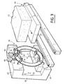
En se référant maintenant aux figures 3 et 4, on va décrire un mode préféré de réalisation de l'appareil de sciage selon l'invention. L'appareil de sciage comprend outre les moyens de sciage proprement dit un chariot 50 sur lequel est placé en porte-à-faux la pièce 40 à scier. Le chariot 50 se déplace sur des rails de guidage 54 qui sont bien sûr parallèles au plan de sciage. Les moyens de sciage 56 comprennent un bâti vertical 58 comportant une aile supérieure 60 et une aile inférieure 62. Les ailes 60 et 62 dégagent ainsi un volume libre horizontal 64 au centre des moyens de sciage. Les moyens de sciage 56 comportent également la couronne de sciage 20 qui est munie sur son bord externe 22 des éléments de sciage 22a représentés ici par des dents. L'entraînement en rotation de la couronne 20 autour de son axe xx'est assuré par exemple par deux moteurs électriques 66 et 68 qui entraînent deux disques à friction 70 et 72 agissant sur chaque face 20a et 20b de la couronne. On retrouve également les galets de centrage 30 qui sont par exemple montés fous sur des axes horizontaux 74 solidaires respectivement des ailes supérieure 60 et inférieure 62 du bâti 58. Sur la figure 3, on a également représenté des rouleaux de guidage 32 qui coopèrent avec des contre-rouleaux, non représentés, pour maintenir la couronne 20 dans son plan de sciage par rapport à l'axe de rotation xx′.Referring now to Figures 3 and 4, we will describe a preferred embodiment of the sawing apparatus according to the invention. The sawing apparatus further comprises the sawing means proper a
Il va de soi que l'entraînement de la couronne 20 en rotation et le guidage de cette couronne ainsi que son centrage pourraient être assurés par d'autres moyens que ceux qui ont été décrits à titre d'exemples en liaison avec les figures 3 et 4. Il faut cependant que ces moyens de guidage, de centrage et d'entraînement soient disposés de telle manière qu'ils laissent libre la zone médiane 64 pour permettre le passage de la pièce à scier 52.It goes without saying that the driving of the
De même, comme on l'a déjà indiqué, les éléments de sciage pourraient être disposés sur le bord interne de la couronne 20. Dans ce cas, on comprend que le chariot doit d'abord permettre d'imprimer à la pièce à scier un déplacement parallèle à l'axe XX′ de rotation de la couronne 20 pour amener la partie de la pièce à scier à l'intérieur de la couronne dans le plan de sciage convenable. Ensuite, le chariot 50 est animé du mouvement de translation déjà décrit pour effectuer le sciage.Likewise, as already indicated, the sawing elements could be arranged on the internal edge of the
En outre, la zone libre de sciage est disposée horizontalement. On comprend qu'on ne sortira pas de l'invention si cette zone était disposée verticalement ou selon toute direction angulaire convenable.In addition, the free sawing area is arranged horizontally. It is understood that we will not depart from the invention if this zone was arranged vertically or in any suitable angular direction.
De même, au lieu que ce soit la pièce à scier qui soit déplacée par rapport aux moyens de sciage 56, on pourrait prévoir un appareil de sciage dans lequel la pièce 40 à scier est maintenue verticale, les moyens de sciage étant alors déplacés et globalement en translation.Similarly, instead of the workpiece being moved relative to the sawing means 56, a sawing device could be provided in which the
Une autre caractéristique de l'invention consiste dans le fait que la lame formée par la couronne est guidée et maintenue (galets, rouleaux) très près du bord de sciage. Cela permet de réduire sensiblement l'épaisseur de la couronne. De préférence, cette épaisseur est inférieure ou égale à 9 mm. Les essais effectués avec une lame de 5 mm d'épaisseur et de 5 mm de diamètre ont montré qu'on obtient une très bonne planéité de la découpe malgré l'épaisseur réduite. Cependant, on comprend que l'épaisseur de la lame doit être en rapport avec le diamètre de celle-ci. Pour des très grandes diamètres de lame, on pourrait être amené à utiliser une épaisseur supérieure à 1 cm, ce qui reste inférieur aux épaisseurs de lames utilisées précédemment pour de tels diamètres. Cela entraîne trois avantages principaux : le coût de fabrication de la scie est réduite ; l'épaisseur du trait de scie est également diminuée, ce qui entraîne une moindre perte de matériau minéral ; enfin, la pénétration de la lame (couronne) dans le matériau est améliorée. De plus, les éléments d'entraînement de la couronne agissent sur les faces 20a,20b de celle-ci. Cela permet d'appliquer effectivement à la couronne le couple nécessaire pour obtenir le sciage de pièces en matériau minéral dur du type marbre ou granit.Another characteristic of the invention consists in the fact that the blade formed by the crown is guided and maintained (rollers, rollers) very close to the sawing edge. This makes it possible to significantly reduce the thickness of the crown. Preferably, this thickness is less than or equal to 9 mm. Tests carried out with a blade 5 mm thick and 5 mm in diameter have shown that very good flatness of the cut is obtained despite the reduced thickness. However, it is understood that the thickness of the blade must be related to the diameter thereof. For very large blade diameters, it could be necessary to use a thickness greater than 1 cm, which remains less than the blade thicknesses used previously for such diameters. This has three main advantages: the cost of manufacturing the saw is reduced; the thickness of the saw cut is also reduced, which results in less loss of mineral material; finally, the penetration of the blade (crown) into the material is improved. In addition, the drive elements of the crown act on the faces 20a, 20b thereof. This makes it possible to effectively apply to the crown the torque necessary to obtain the sawing of pieces of hard mineral material of the marble or granite type.
Pour certains travaux, il peut être intéressant d'utiliser un deuxième mode de réalisation de l'installation de sciage qui va être décrit en liaison avec les figures 5 et 6.For certain works, it may be advantageous to use a second embodiment of the sawing installation which will be described in conjunction with FIGS. 5 and 6.
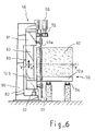
L'installation comporte, d'une part, le chariot 50 et, d'autre part, un appareil de sciage portant la référence générale 56 qui est du même type que celui qui est décrit en liaison avec les figures 2 à 4. L'appareil de sciage est constitué essentiellement par une lame 20 en forme de couronne circulaire de centre 0. La périphérie externe 22 de la lame 20 est munie des organes de sciage convenables, tels que des dents ou des segments diamantés. La lame circulaire 20 est montée à rotation autour d'un axe XX′ passant par son centre 0 grâce à des galets de guidage et de centrage 30 et à des patins 32 pour maintenir la lame 20 dans un plan vertical constant. En outre, un système d'entraînement à rotation 66 coopère avec les faces principales de la lame, par exemple par l'intermédiaire de galets 70 et de contre-galets pour provoquer la rotation de la lame autour de l'axe XX′. Dans le mode de réalisation présentement décrit, l'ensemble des éléments de guidage 30,32 et des éléments d'entraînement en rotation 66,70 sont montés sur un premier bâti 80 constitué par une poutre supérieure 81, une poutre inférieure 82 et des montants 83 et 84. Les éléments de guidage 30,32 et les éléments d'entraînement à rotation 66,70 sont disposés de telle manière qu'il existe un volume de hauteur H de part et d'autre du centre de la lame 20 qui soit totalement libre pour le passage du bloc 18 à scier et du chariot 50. On comprend qu'ainsi comme on l'a déjà indiqué, la lame 20 attaque frontalement le bloc à scier et non tangentiellement.The installation comprises, on the one hand, the
Comme le montre mieux la figure 6, le chariot 50 se déplace sur des rails de guidage tels que 54 qui sont bien sûr disposés parallèlement à la direction de sciage D. La figure 6 montre également que la partie principale 12a du plateau du chariot 50 se trouve à "l'extérieur" de la lame 20 alors que la partie latérale 12b se trouve entre la lame 20 et le premier bâti.As best shown in Figure 6, the
La figure 6 montre également que l'ensemble du premier bâti 80 est monté sur un deuxième bâti fixe 90 par l'intermédiaire d'un ensemble de vérins 92 permettant de provoquer un déplacement en translation verticale V du premier bâti 80 par rapport au bâti fixe 90. Il va de soi qu'on pourrait utiliser d'autres moyens de déplacement alternatif, par exemple un excentrique commandé par un moteur. Le bâti fixe 90 comporte également des moyens de guidage en translation du bâti mobile 80, ces moyens n'étant pas représentés sur les figures. On comprend qu'ainsi, en plus du mouvement de rotation de la lame 20 autour de l'axe horizontal XX′, la lame est animée d'un mouvement alternatif de translation de direction V et d'amplitude prédéterminée par exemple de l'ordre de 5 à 8 cm de part et d'autre de sa position médiane.FIG. 6 also shows that the assembly of the
Le fait que la lame soit animée de ce mouvement alternatif de translation verticale permet d'améliorer l'efficacité du sciage en évitant des phénomènes de bourrage de la poudre résultant du sciage entre la partie de la pièce à scier et les organes de sciage de la lame. Plus précisément ce mouvement vertical permet un auto-ravivage des éléments de sciage lorsque ceux-ci sont en particulier constitués par des pastilles de diamant.The fact that the blade is driven by this alternating movement of vertical translation makes it possible to improve the efficiency of sawing by avoiding phenomena of stuffing of the powder resulting from sawing between the part of the workpiece to be sawn and the sawing members of the blade. More precisely, this vertical movement allows self-resuscitation of the sawing elements when they are in particular constituted by diamond pellets.
Il faut comprendre que ce mouvement alternatif supplémentaire de la lame n'est pas nécessairement obtenu par un mouvement alternatif de translation verticale du bâti mobile par rapport au bâti fixe. Il suffit que ce mouvement présente une composante perpendiculaire à la direction de sciage dans le plan de sciage. Cela peut aussi être obtenu en montant le bâti portant la couronne à l'extrémité d'un bras animé d'un mouvement de rotation alternée autour d'un axe fixe parallèle à l'axe de la couronne d'une amplitude limitée par exemple de 5 à 8 cm par rapport à l'horizontale. Ce mouvement additionnel relatif peut également être obtenu en prévoyant que le plateau sur lequel repose directement la pièce à scier soit animé d'un mouvement alternatif de rotation d'amplitude limitée par rapport au chassis du chariot autour d'un axe parallèle à l'axe XX′ de la couronne 20. On obtient ainsi un mouvement alternatif présentant une composante perpendiculaire à la direction de sciage c'est-à-dire à la direction de déplacement du chariot.It should be understood that this additional reciprocating movement of the blade is not necessarily obtained by an alternating movement of vertical translation of the movable frame relative to the fixed frame. It suffices that this movement has a component perpendicular to the sawing direction in the sawing plane. This can also be obtained by mounting the frame carrying the crown at the end of an arm driven by an alternating rotation movement around a fixed axis parallel to the axis of the crown of limited amplitude, for example of 5 to 8 cm from the horizontal. This additional relative movement can also be obtained by providing that the plate on which the workpiece is directly resting is driven by an alternating movement of rotation of limited amplitude relative to the chassis of the carriage around an axis parallel to the axis. XX ′ of the
En se référant maintenant aux figures 7 à 12, on va décrire des modes préférés de réalisation du chariot, notamment utilisable dans l'installation de sciage décrit précédemment.Referring now to Figures 7 to 12, we will describe preferred embodiments of the carriage, in particular usable in the sawing installation described above.
En se référant tout d'abord aux figures 7 à 9, on va décrire un premier mode de réalisation du dispositif de déplacement, ultérieurement appelé chariot. Comme le montre la figure 7, le chariot 110 est constitué par un plateau horizontal 112 sur lequel sont fixées quatre roues de roulement, ou galets, tels que 113. Un organe moteur 115 permet de commander le déplacement du chariot 110 sur des rails de guidage non représentés.Referring first to Figures 7 to 9, we will describe a first embodiment of the displacement device, later called carriage. As shown in Figure 7, the
Le plateau 112 du chariot est destiné à recevoir un bloc de matériau minéral 118 qui repose sur la face supérieure du plateau. Comme on le voit sur la figure 8, sur une partie latérale du plateau 112 par rapport à la direction de déplacement D du chariot est disposé un système de bras 120, 122 qui sont solidaires d'un axe de rotation 124 disposé parallèlement à la direction de déplacement D. L'axe de rotation est monté pivotant par l'intermédiaire de paliers tels que 126 solidaires du plateau 112. Le pivotement simultané des bras 120 et 122 autour de l'axe 124 est commandé par un ou deux vérins 130. Chaque vérin 130 comporte un corps 130a qui est articulé sur une pièce 132 solidaire du plateau 112 et une tige 130b dont l'extrémité est solidaire du bras correspondant 120 ou 122. On comprend au vu des figures 8 et 9 qu'en commandant le ou les vérins on peut faire passer le bras 120 de sa position verticale représentée sur la figure à une position horizontale représentée sur la figure 9. La face interne 120a de chaque bras 120 est munie d'organes de solidarisation tels que 134 qui permettent de réaliser une solidarisation entre le bras 120 et la face 118b du bloc 118 à scier. Plus précisément, cette face 118b correspond à la plaque 118a qui doit être sciée à partir du bloc total. De préférence, les organes de solidarisation 134 sont constitués par des systèmes à dépression en forme de ventouses déformables qui sont reliés à une source de vide non représentée.The
On comprend qu'après le sciage d'une première plaque 118a, il est nécessaire de déplacer l'ensemble du bloc restant 118 selon la direction D′ perpendiculaire à la direction de sciage D pour amener le bloc dans sa nouvelle position de sciage. Pour cela, le plateau 112 est muni d'un dispositif de déplacement du bloc, selon la direction D′, ce système portant la référence générale 136. Le système de déplacement latéral 136 permet de déplacer, selon la direction D′, le bloc 118 d'un pas égal à l'épaisseur e des plaques à scier. Le dispositif 136 sera décrit ultérieurement plus en détails dans un mode préféré de réalisation.It is understood that after sawing a first plate 118a, it is necessary to move the entire remaining
Avec certains appareils de sciage, notamment ceux qui sont décrits en liaison avec les figures 1 à 6, la lame de sciage ou l'organe de sciage n'attaque pas tangentiellement le bloc 118 mais frontalement. On comprend que, dans ce cas, il est nécessaire que le chariot 110 présente le bloc 118 dans la position requise. Pour permettre ce positionnement correct, il est nécessaire que le chariot présente une fente parallèle à la direction de sciage D permettant le passage de la partie inférieure de l'organe de sciage. C'est ce qu'on a représenté sur la figure 10. Le plateau 112 du chariot est constitué par une partie principale 112a et par une portion latérale 112b qui sont séparées par une fente parallèle à la direction D de déplacement du chariot. La fente 140 ne se poursuit pas jusqu'à l'extrémité arrière 112c du plateau 112. Une pièce de solidarisation 142 assure la liaison mécanique entre la partie principale 112a et la partie latérale 112b, tout en dégageant la fente 140 sur la course utile de sciage.With certain sawing devices, in particular those which are described in conjunction with FIGS. 1 to 6, the saw blade or the saw member does not tangentially attack the
Sur la figure 10, on a représenté montés sur la partie latérale 112b du plateau les bras pivotants 120, 122 ainsi que l'axe de rotation 124. Pour permettre le déplacement selon la direction D′ du bloc 118, le plateau 112 est muni de moyens de supportage du bloc qui sont constitués, par exemple, par deux premières portions d'IPN 150 et 152 solidaires de la partie principale 112a du plateau et disposées parallèlement à la direction D′ et par deux portions d'IPN 154 et 156 également parallèles à cette direction mais solidaires de la partie latérale du plateau 112b et prolongeant les portions 152 et 150. Sur la partie principale 112a du plateau et disposé entre les éléments de supportage 150 et 152, on trouve un ensemble de galets de roulement tels que 158 permettant un déplacement selon la direction D′. Sur ces galets est disposée une plaque horizontale 160 placée également entre les éléments de supportage 150 et 152. Sur la face supérieure de la plaque 160 sont fixées les corps 162a, 164a, 166a et 168a de quatre vérins 162 à 168 à déplacement vertical. Les tiges 162b à 168b de ces vérins sont solidaires de plaquettes de soulèvement 162c à 168C. Lorsque le vérin est au repos, c'est-à-dire que les tiges sont totalement rentrées, les plaquettes 162 sont en retrait par rapport aux faces supérieures 150a et 152a des éléments de supportage 150 et 152. Dans cette position, le bloc 118 est donc en appui sur les éléments de supportage. Au contraire, lorsque les tiges 162b à 168b sont en position sortie, les plaquettes 162c à 168c provoquent un léger soulèvement du bloc 118 par rapport aux éléments de supportage 150 et 152. En outre, un vérin 170 solidaire du plateau 112 ou plus précisément de sa partie principale 112a permet de déplacer la plaque 160 parallèlement à la direction D′ d'une distance telle que, dans une première position, la plaque 160 soit entièrement disposée au-dessus de la partie principale 112a du plateau 112 et que, dans une deuxième position, cette plaque 160 soit également au-dessus de la partie latérale 112b du plateau comprise entre les éléments de supportage 154 et 156.In FIG. 10, there are shown mounted on the
Le fonctionnement du chariot est le suivant : le bloc 118 est initialement disposé sur les éléments de supportage 150 à 156 du plateau de telle manière que la partie à scier 118a soit au-dessus des éléments de supportage 154 et 156. Le chariot 110 est déplacé grâce au moteur 115 de telle manière qu'il présente une course correspondant à la longueur de sciage. Puis le chariot est déplacé dans la direction inverse. Dans cette première phase, les bras 120 sont en position verticale et les éléments de solidarisation 134 sont activés. Lors du retour à la position initiale, il suffit alors de commander les vérins 130 pour amener les bras 120 dans une position horizontale telle que représentée sur la figure 9. La plaque découpée 118a est ainsi amenée à l'extérieur du plateau 112 en position horizontale. Il est alors aisé, à l'aide d'un chariot élévateur, de saisir la plaque 118a et de la stocker à un endroit convenable. Dans cette position du chariot, les vérins 130 sont à nouveau commandés pour ramener les bras en position verticale. La course est telle que les éléments de solidarisation 134 arrivent à nouveau en contact avec la face latérale du reste du bloc à découper. Dans la phase suivante, on provoque le déplacement du bloc 118 selon la direction D′ d'une longueur correspondant à l'épaisseur de la plaque. Pour cela, on provoque le soulèvement des vérins 162 à 168, ce qui entraîne le soulèvement du bloc 118 qui n'est plus en appui sur les éléments de supportage 150 à 156. Tout en maintenant les vérins de soulèvement activés, on commande le vérin 170 pour provoquer le déplacement, selon la direction D′, de l'ensemble de la plaque 160, ce qui entraîne la déplacement simultané dans cette direction du bloc 118 dont la partie à scier vient au-dessus des éléments de supportage 154 et 156 de la partie latérale 112b du plateau. Dans cette position, on commande le retrait des tiges de vérin de telle manière que le bloc 118 vienne en appui sur les éléments de supportage 150 à 156, le bloc étant en position pour l'opération de sciage suivante. On commande alors le vérin 170 pour ramener la plaque 160 dans sa position initiale, c'est-à-dire celle qui est représentée sur la figure 12.The operation of the carriage is as follows: the
Un autre problème consiste dans le fait qu'avec les appareils de sciage de très grandes dimensions, leur transport est plus délicat, en particulier en raison du diamètre important de la lame, les autres parties de l'appareil pouvant être démontées sans difficulté particulière.Another problem consists in the fact that with very large sawing apparatuses, their transport is more delicate, in particular because of the large diameter of the blade, the other parts of the apparatus being able to be dismantled without particular difficulty.
Pour remédier à cet inconvénient, on va décrire un mode de réalisation de l'organe de sciage ou lame démontable tout en assurant une grande efficacité de sciage. Ce mode de réalisation est illustré par les figures 13 et 14.To remedy this drawback, an embodiment of the sawing member or removable blade will be described while ensuring high sawing efficiency. This embodiment is illustrated by FIGS. 13 and 14.
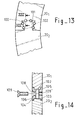
La couronne 20 formant la lame est constituée par plusieurs segments de couronne, par exemple trois 20₁, 20₂, 20₃ de dimensions identiques. Les extrémités de chaque segment se terminent par un assemblage en queue d'arronde 100, 101. On obtient ainsi la solidarisation des segments selon la circonférence de la lame. La solidarisation des éléments, selon la direction de l'axe de rotation XX′ de la lame est réalisée de la manière suivante :The
Dans le plan de raccordement des deux parties de la queue d'arronde 100, 101 sont percés des orifices tels que 102 qui appartiennent aux deux segments 20₁ et 20₂. Comme le montre la figure 14, l'orifice 102 comporte un lamage 103, 104 à son débouché dans les faces 20a, 20b des segments. Des pastilles métalliques 106, 105 comportant chacune un épaulement 107 peuvent être introduites dans l'orifice 102, les épaulements 107 étant logés dans les lamages 103, 104. La pastille 105 comporte un orifice conique 108 pour recevoir la tête d'une vis fraisée 109. La pastille 105 comporte un taraudage 109'pour la vis 109. Après introduction des pastilles 105, 105 et le serrage des vis 109, on obtient une excellente solidarisation des segments de la couronne tout en autorisant un démontage commode de celle-ci.In the connection plane of the two parts of the
Claims (15)
un organe de sciage en forme de couronne (20) plane circulaire dont le diamètre est au moins égal à 3 mètres, présentant un bord interne (22) circulaire et un bord externe circulaire (20), et dont l'épaisseur est réduite, un desdits bords étant muni sur toute sa périphérie d'éléments de sciage (22a) ;
des moyens de mise en rotation (66, 68) de l'organe de sciage autour d'un axe (XX′) passant par son centre (0) agissant sur les faces de ladite couronne (20a, 20b) ;
des moyens (30, 32) pour guider en rotation ledit organe de sciage pour maintenir ledit organe de sciage dans un plan fixe perpendiculaire audit axe de rotation et pour le maintenir en rotation autour dudit axe, lesdits moyens de mise en rotation et lesdits moyens de guidage étant disposés à l'extérieur d'un volume parallélépipédique rectangle (34, 36, 38, 64) disposé parallèlement au plan de la couronne et contenant le centre (0) de celle-ci ; et
un chariot pour recevoir ladite pièce à scier et la déplacer par rapport à l'organe de sciage selon la direction d'un diamètre dudit organe de sciage.Installation for sawing mineral pieces of the marble, marble slab or granite type, characterized in that it comprises a weaving apparatus comprising:
a circular flat crown-shaped sawing member (20) whose diameter is at least equal to 3 meters, having a circular internal edge (22) and a circular external edge (20), and whose thickness is reduced, a said edges being provided over its entire periphery with sawing elements (22a);
means for rotating (66, 68) the sawing member about an axis (XX ′) passing through its center (0) acting on the faces of said ring (20a, 20b);
means (30, 32) for guiding said sawing member in rotation to maintain said sawing member in a fixed plane perpendicular to said axis of rotation and for keeping it in rotation about said axis, said means for rotating and said means for guide being arranged outside a rectangular parallelepiped volume (34, 36, 38, 64) disposed parallel to the plane of the crown and containing the center (0) thereof; and
a carriage for receiving said workpiece and moving it relative to the sawing member in the direction of a diameter of said sawing member.
Applications Claiming Priority (4)
| Application Number | Priority Date | Filing Date | Title |
|---|---|---|---|
| FR9103655A FR2674469B1 (en) | 1991-03-26 | 1991-03-26 | SAWING APPARATUS. |
| FR9103655 | 1991-03-26 | ||
| FR9113521A FR2683177B1 (en) | 1991-10-31 | 1991-10-31 | DEVICE FOR MOVING WORKPIECES, ESPECIALLY MINERALS, AND SAWING INSTALLATION USING THE MOVEMENT DEVICE. |
| FR9113521 | 1991-10-31 |
Publications (2)
| Publication Number | Publication Date |
|---|---|
| EP0506533A1 true EP0506533A1 (en) | 1992-09-30 |
| EP0506533B1 EP0506533B1 (en) | 1997-05-28 |
Family
ID=26228591
Family Applications (1)
| Application Number | Title | Priority Date | Filing Date |
|---|---|---|---|
| EP92400772A Expired - Lifetime EP0506533B1 (en) | 1991-03-26 | 1992-03-23 | Sawing apparatus |
Country Status (4)
| Country | Link |
|---|---|
| EP (1) | EP0506533B1 (en) |
| AT (1) | ATE153588T1 (en) |
| DE (1) | DE69219938T2 (en) |
| ES (1) | ES2107509T3 (en) |
Cited By (5)
| Publication number | Priority date | Publication date | Assignee | Title |
|---|---|---|---|---|
| EP1375042A1 (en) * | 2002-06-17 | 2004-01-02 | Ilario Veronesi | Machine for splitting strips of stone materials and the like in two |
| JP2010142885A (en) * | 2008-12-17 | 2010-07-01 | Hitachi Koki Co Ltd | Cutting tool |
| WO2014146794A1 (en) * | 2013-03-21 | 2014-09-25 | Rfsdesign Ug (Haftungsbeschränkt) | Device head for a machine tool, in particular for an annular saw or an angle grinder |
| CN105328799A (en) * | 2015-11-05 | 2016-02-17 | 芜湖赛特施工设备有限公司 | False bracket removing device |
| US11433464B2 (en) | 2018-08-28 | 2022-09-06 | Techtronic Power Tools Technology Limited | Tile saw |
Citations (5)
| Publication number | Priority date | Publication date | Assignee | Title |
|---|---|---|---|---|
| DE1205258B (en) * | 1960-06-30 | 1965-11-18 | Willem Koelega | Circular saw machine |
| US4350552A (en) * | 1972-09-04 | 1982-09-21 | Bourke Patrick T | Method and apparatus for cutting stone panels |
| DE3823782A1 (en) * | 1987-07-14 | 1989-02-02 | Tecno Sameg Srl | MACHINE FOR CUTTING STONES |
| DE3801487A1 (en) * | 1988-01-20 | 1989-08-03 | Gerhard Bihler | Annular circular saw, in particular for wood and stone |
| DE8906577U1 (en) * | 1989-05-29 | 1989-08-03 | Fritz Haug Ag, St. Gallen, Ch |
-
1992
- 1992-03-23 EP EP92400772A patent/EP0506533B1/en not_active Expired - Lifetime
- 1992-03-23 DE DE69219938T patent/DE69219938T2/en not_active Expired - Fee Related
- 1992-03-23 ES ES92400772T patent/ES2107509T3/en not_active Expired - Lifetime
- 1992-03-23 AT AT92400772T patent/ATE153588T1/en active
Patent Citations (5)
| Publication number | Priority date | Publication date | Assignee | Title |
|---|---|---|---|---|
| DE1205258B (en) * | 1960-06-30 | 1965-11-18 | Willem Koelega | Circular saw machine |
| US4350552A (en) * | 1972-09-04 | 1982-09-21 | Bourke Patrick T | Method and apparatus for cutting stone panels |
| DE3823782A1 (en) * | 1987-07-14 | 1989-02-02 | Tecno Sameg Srl | MACHINE FOR CUTTING STONES |
| DE3801487A1 (en) * | 1988-01-20 | 1989-08-03 | Gerhard Bihler | Annular circular saw, in particular for wood and stone |
| DE8906577U1 (en) * | 1989-05-29 | 1989-08-03 | Fritz Haug Ag, St. Gallen, Ch |
Cited By (5)
| Publication number | Priority date | Publication date | Assignee | Title |
|---|---|---|---|---|
| EP1375042A1 (en) * | 2002-06-17 | 2004-01-02 | Ilario Veronesi | Machine for splitting strips of stone materials and the like in two |
| JP2010142885A (en) * | 2008-12-17 | 2010-07-01 | Hitachi Koki Co Ltd | Cutting tool |
| WO2014146794A1 (en) * | 2013-03-21 | 2014-09-25 | Rfsdesign Ug (Haftungsbeschränkt) | Device head for a machine tool, in particular for an annular saw or an angle grinder |
| CN105328799A (en) * | 2015-11-05 | 2016-02-17 | 芜湖赛特施工设备有限公司 | False bracket removing device |
| US11433464B2 (en) | 2018-08-28 | 2022-09-06 | Techtronic Power Tools Technology Limited | Tile saw |
Also Published As
| Publication number | Publication date |
|---|---|
| EP0506533B1 (en) | 1997-05-28 |
| ES2107509T3 (en) | 1997-12-01 |
| DE69219938T2 (en) | 1998-01-08 |
| ATE153588T1 (en) | 1997-06-15 |
| DE69219938D1 (en) | 1997-07-03 |
Similar Documents
| Publication | Publication Date | Title |
|---|---|---|
| EP2705937B1 (en) | Wooden logs sawing machine | |
| EP0926084A1 (en) | Transfer device and conveyor equipped with such a device | |
| EP0506533B1 (en) | Sawing apparatus | |
| FR2559264A1 (en) | MICROTOME PROVIDED WITH MEANS FOR WITHDRAWING THE SPECIMEN | |
| FR2567057A1 (en) | APPARATUS FOR GRINDING GLASS PLATES | |
| EP0125175A1 (en) | Apparatus for cutting continuously manufactured cardboard tubes | |
| FR2487310A1 (en) | Continuous pick=up mechanism for foils - has suction heads carried on rods rotated via levers, radial arms, and gears to move tangentially to foils | |
| EP0081533A1 (en) | Method and device for threading spikes on a spike wheel hub. | |
| EP0082748A1 (en) | Plane frontal rectifying machine for rectifying the ends of optic fibres | |
| EP0094881A1 (en) | Band saw and casing supporting the blade of such a saw | |
| EP0007264A1 (en) | Chain flexible in only one direction and application to a hand rail | |
| FR2469259A1 (en) | Silicone waver prodn. system - combines cutting and grinding stages into single operation | |
| FR2918652A1 (en) | ROTARY DEVICE FOR TRANSFER AND INDEXATION OF METALLIC OBJECTS HAVING CONTACTLESS DRIVING MEANS. | |
| CH453027A (en) | Device for continuous wire winding on take-up reels | |
| EP0115759B1 (en) | Method and apparatus to remove the cut-off end from a tubular workpiece, e.g. a cast-iron pipe | |
| EP0045272A1 (en) | Blocking device for a workpiece during a manufacturing operation such as drilling | |
| FR2627761A1 (en) | Flat plate transfer transformer - has scissors jack carrying chassis with suction plate and plate alignment stops | |
| FR2683177A1 (en) | Device for the displacement of components, particularly mineral ones, and sawing installation using the displacement device | |
| WO2019229391A1 (en) | Station for the automated sawing of wheel rims for bicycles | |
| EP0224419A1 (en) | In situ machining or measuring method and apparatus for a rotating work piece | |
| FR2674469A1 (en) | Sawing appliance | |
| EP0035939A1 (en) | Machine with a rotating implement for copying or finishing operations | |
| FR2713973A1 (en) | Ingot mould interior cleaner | |
| FR3031688A1 (en) | MACHINE CUTTING OR SLICING MULTI-KNIVES | |
| FR2584334A1 (en) | Machine for cutting out thin sheets in the shape of discs |
Legal Events
| Date | Code | Title | Description |
|---|---|---|---|
| PUAI | Public reference made under article 153(3) epc to a published international application that has entered the european phase |
Free format text: ORIGINAL CODE: 0009012 |
|
| AK | Designated contracting states |
Kind code of ref document: A1 Designated state(s): AT BE CH DE DK ES FR GB GR IT LI NL PT SE |
|
| 17P | Request for examination filed |
Effective date: 19930315 |
|
| 17Q | First examination report despatched |
Effective date: 19931221 |
|
| ITCL | It: translation for ep claims filed |
Representative=s name: NOTARO E ANTONELLI |
|
| GRAG | Despatch of communication of intention to grant |
Free format text: ORIGINAL CODE: EPIDOS AGRA |
|
| GRAH | Despatch of communication of intention to grant a patent |
Free format text: ORIGINAL CODE: EPIDOS IGRA |
|
| GRAH | Despatch of communication of intention to grant a patent |
Free format text: ORIGINAL CODE: EPIDOS IGRA |
|
| GRAA | (expected) grant |
Free format text: ORIGINAL CODE: 0009210 |
|
| AK | Designated contracting states |
Kind code of ref document: B1 Designated state(s): AT BE CH DE DK ES FR GB GR IT LI NL PT SE |
|
| PG25 | Lapsed in a contracting state [announced via postgrant information from national office to epo] |
Ref country code: NL Free format text: LAPSE BECAUSE OF FAILURE TO SUBMIT A TRANSLATION OF THE DESCRIPTION OR TO PAY THE FEE WITHIN THE PRESCRIBED TIME-LIMIT Effective date: 19970528 Ref country code: GR Free format text: LAPSE BECAUSE OF FAILURE TO SUBMIT A TRANSLATION OF THE DESCRIPTION OR TO PAY THE FEE WITHIN THE PRESCRIBED TIME-LIMIT Effective date: 19970528 Ref country code: GB Effective date: 19970528 Ref country code: DK Effective date: 19970528 Ref country code: AT Effective date: 19970528 |
|
| REF | Corresponds to: |
Ref document number: 153588 Country of ref document: AT Date of ref document: 19970615 Kind code of ref document: T |
|
| REG | Reference to a national code |
Ref country code: CH Ref legal event code: EP |
|
| REF | Corresponds to: |
Ref document number: 69219938 Country of ref document: DE Date of ref document: 19970703 |
|
| ITF | It: translation for a ep patent filed |
Owner name: BUZZI, NOTARO&ANTONIELLI D'OULX |
|
| PG25 | Lapsed in a contracting state [announced via postgrant information from national office to epo] |
Ref country code: SE Effective date: 19970828 |
|
| NLV1 | Nl: lapsed or annulled due to failure to fulfill the requirements of art. 29p and 29m of the patents act | ||
| GBV | Gb: ep patent (uk) treated as always having been void in accordance with gb section 77(7)/1977 [no translation filed] |
Effective date: 19970528 |
|
| REG | Reference to a national code |
Ref country code: PT Ref legal event code: SC4A Free format text: AVAILABILITY OF NATIONAL TRANSLATION Effective date: 19970819 |
|
| REG | Reference to a national code |
Ref country code: ES Ref legal event code: FG2A Ref document number: 2107509 Country of ref document: ES Kind code of ref document: T3 |
|
| PG25 | Lapsed in a contracting state [announced via postgrant information from national office to epo] |
Ref country code: ES Free format text: LAPSE BECAUSE OF EXPIRATION OF PROTECTION Effective date: 19980324 |
|
| PG25 | Lapsed in a contracting state [announced via postgrant information from national office to epo] |
Ref country code: LI Free format text: LAPSE BECAUSE OF NON-PAYMENT OF DUE FEES Effective date: 19980331 Ref country code: CH Free format text: LAPSE BECAUSE OF NON-PAYMENT OF DUE FEES Effective date: 19980331 Ref country code: BE Free format text: LAPSE BECAUSE OF NON-PAYMENT OF DUE FEES Effective date: 19980331 |
|
| PLBE | No opposition filed within time limit |
Free format text: ORIGINAL CODE: 0009261 |
|
| STAA | Information on the status of an ep patent application or granted ep patent |
Free format text: STATUS: NO OPPOSITION FILED WITHIN TIME LIMIT |
|
| 26N | No opposition filed | ||
| BERE | Be: lapsed |
Owner name: MOGAVERO COSIMO Effective date: 19980331 |
|
| PG25 | Lapsed in a contracting state [announced via postgrant information from national office to epo] |
Ref country code: PT Free format text: LAPSE BECAUSE OF NON-PAYMENT OF DUE FEES Effective date: 19980930 |
|
| REG | Reference to a national code |
Ref country code: CH Ref legal event code: PL |
|
| PG25 | Lapsed in a contracting state [announced via postgrant information from national office to epo] |
Ref country code: DE Free format text: LAPSE BECAUSE OF NON-PAYMENT OF DUE FEES Effective date: 19981201 |
|
| REG | Reference to a national code |
Ref country code: PT Ref legal event code: MM4A Free format text: LAPSE DUE TO NON-PAYMENT OF FEES Effective date: 19980930 |
|
| REG | Reference to a national code |
Ref country code: ES Ref legal event code: FD2A Effective date: 20000601 |
|
| PGFP | Annual fee paid to national office [announced via postgrant information from national office to epo] |
Ref country code: FR Payment date: 20010316 Year of fee payment: 10 |
|
| PG25 | Lapsed in a contracting state [announced via postgrant information from national office to epo] |
Ref country code: FR Free format text: LAPSE BECAUSE OF NON-PAYMENT OF DUE FEES Effective date: 20021129 |
|
| REG | Reference to a national code |
Ref country code: FR Ref legal event code: ST |
|
| PG25 | Lapsed in a contracting state [announced via postgrant information from national office to epo] |
Ref country code: IT Free format text: LAPSE BECAUSE OF NON-PAYMENT OF DUE FEES Effective date: 20050323 |