EP0506403B1 - Method and apparatus for providing phase change ink to an ink jet printer - Google Patents
Method and apparatus for providing phase change ink to an ink jet printer Download PDFInfo
- Publication number
- EP0506403B1 EP0506403B1 EP92302632A EP92302632A EP0506403B1 EP 0506403 B1 EP0506403 B1 EP 0506403B1 EP 92302632 A EP92302632 A EP 92302632A EP 92302632 A EP92302632 A EP 92302632A EP 0506403 B1 EP0506403 B1 EP 0506403B1
- Authority
- EP
- European Patent Office
- Prior art keywords
- ink
- reservoir
- melt chamber
- heat
- print head
- Prior art date
- Legal status (The legal status is an assumption and is not a legal conclusion. Google has not performed a legal analysis and makes no representation as to the accuracy of the status listed.)
- Expired - Lifetime
Links
Images



Classifications
-
- B—PERFORMING OPERATIONS; TRANSPORTING
- B41—PRINTING; LINING MACHINES; TYPEWRITERS; STAMPS
- B41J—TYPEWRITERS; SELECTIVE PRINTING MECHANISMS, i.e. MECHANISMS PRINTING OTHERWISE THAN FROM A FORME; CORRECTION OF TYPOGRAPHICAL ERRORS
- B41J2/00—Typewriters or selective printing mechanisms characterised by the printing or marking process for which they are designed
- B41J2/005—Typewriters or selective printing mechanisms characterised by the printing or marking process for which they are designed characterised by bringing liquid or particles selectively into contact with a printing material
- B41J2/01—Ink jet
- B41J2/17—Ink jet characterised by ink handling
- B41J2/175—Ink supply systems ; Circuit parts therefor
- B41J2/17593—Supplying ink in a solid state
Definitions
- the present invention relates to a method and an apparatus for melting solid sticks of phase change ink and providing the melted ink to an ink jet head.
- the invention in its apparatus sense is particularly but not exclusively concerned with field replaceable unit forms of the apparatus ("FRU" hereinafter means field replaceable unit).
- Ink jet printers eject ink onto a print medium, such as paper, in controlled patterns of closely spaced dots.
- Two commonly used inks are aqueous ink and phase change or hot melt ink.
- Phase change ink has a liquid phase when it is above the melting temperature, for example 86°C, and a solid phase when it is at or below the melting temperature.
- an ink jet apparatus for use with hot melt ink having an integrally connected ink jet head and reservoir system, the reservoir system including a highly efficient heat conducting plate, such as aluminium, inserted within an essentially non-heat conducting reservoir housing.
- the reservoir system has a sloping flow path between an inlet position and a sump from which ink is drawn to the head, and includes a plurality of vanes situated upon the plate for rapid heat transfer.
- Phase change ink is conveniently stored, transported, and inserted into an ink jet printer assembly in solid phase.
- the ink must be in the liquid phase and relatively hot. Because it typically takes a few minutes for phase change ink to melt after heat has been applied to it, there must be a supply of melted ink having the proper temperature for the print head to eject. There is, therefore, a need for a method and an apparatus for melting and storing phase change ink and providing the ink to a print head at the proper temperature.
- An FRU assembly comprises, according to the invention, a melt chamber including multiple subchambers in which sticks of phase change ink are inserted and melted. Melted ink flows through apertures to a reservoir comprising multiple compartments. Each compartment contains a channel and a siphon plate that allow a siphon action that siphons melted ink in the compartments to an orifice that leads to an ink jet print head. Heaters under the control of a CPU melt the ink and keep the melted ink at a desired temperature during various modes of operation.
- the invention provides a method and an apparatus for melting and storing phase change ink and providing the ink to a print head at the proper temperature. It will further be appreciated that the invention provides such an apparatus that controllably and automatically regulates the heat applied to the ink.
- an FRU assembly 10 is used by an ink jet printer to receive and melt solid sticks of hot melt ink and provide the melted ink to a multi-orifice ink jet print head assembly 16 ("head 16") affixed to FRU 10.
- FRU 10 is constructed to be easily inserted as a unit into an ink jet printer assembly of the type described in US Patent Application No 07/633,840 (corresponding to US Patent No 5083143). Head 16 may or may not be considered part of FRU 10. If there is a defect in a particular FRU 10, then a new FRU 10 may be inserted into the ink jet printer assembly with a minimal amount of downtime. It is for that reason that FRU 10 is referred to as "field replaceable".
- FRU 10 is comprised of a melt chamber 20, a wire cloth mesh filter 24, and a reservoir 28.
- FRU 10 provides melted ink in multiple colors, for example, cyan, yellow, magenta, and black. The ink of each of these colors is physically separated from the ink of the other colors throughout melt chamber 20 and reservoir 28. Therefore, for convenience in tracing the travel of the ink, the letter “A” is associated with cyan ink, “B” is associated with yellow ink, "C” is associated with magenta ink, and "D” is associated with black ink.
- Fig. 3 shows only the portions of FRU 10 that are used in connection with cyan ink.
- Melt chamber 20 is divided into subchambers 30A, 30B, 30C, and 30D (collectively “subchambers 30"), and air chambers 34A, 34B, 34C, 34D1, and 34D2 (collectively “air chambers 34"), as described below with reference to Fig. 3.
- Subchamber 30D which is divided by divider 44, holds twice as many sticks as the other subchambers because black ink is typically used more frequently than the other colors.
- sticks 38A and 40A of cyan ink are placed through an opening 42A in the top of subchamber 30A.
- Ink stick 38A rests against a floor 46 and a melt plate 48, the latter of which subdivides subchambers 30 from air chambers 34.
- Stick 40A rests against stick 38A and plate 48.
- Ink sticks 38B and 38C (not shown) rest against floor 46 and plate 48 in subchambers 30B and 30C, respectively.
- Ink sticks 40B and 40C rest against sticks 38B and 38C and plate 48.
- Ink sticks 38D1 and 38D2 (not shown), rest against floor 46 and plate 48 in subchamber 30D.
- Ink sticks 40D1 and 40D2 rests against sticks 38D1 and 38D2 and plate 48.
- Melt chamber 20 is bounded by side walls 49 and 50.
- Melt chamber 20 is preferably formed of a single piece of magnesium, which is light weight and heat conductive. Melt chamber 20 is heated by a resistive-type heater element 52 that causes sticks 38A-38D2 and 40A-40D2 to melt.
- heater 52 is a standard 1/4 inch (6.35 millimeters ("mm")) diameter cartridge heater, such as one manufactured by Watlow.
- Heater 52 is placed next to plate 48 and across the width of melt chamber 20. The ends of heater 52 are shown on side walls 49 and 50 in Figs. 1 and 2.
- a thermistor 60 measures the temperature of the surface of melt chamber 20 at a convenient location, such as the side of melt chamber 20 shown in Fig. 1.
- melted ink flows under the force of gravity from subchambers 30A, 30B, and 30C through apertures 54A, 54B, and 54C to air chambers 34A, 34B, and 34C, respectively.
- Apertures 54D1 and 54D2 allow ink to flow from subchamber 30D to air chambers 34D1 and 34D2.
- Air chambers 34 are separated by plates 62, 64, 66, and 68.
- Ribs 70A, 70B, 70C, 70D1, and 70D2 are used in connection with an air flow system, discussed below.
- reservoir 28 is divided into compartments 56A, 56B, 56C, 56D1, and 56D2 by plates 72, 74, 76, and 78.
- Reservoir 28 is bounded by side walls 79 and 80, as best shown in Figs. 1 and 2.
- filter 24 is placed between melt chamber 20 and reservoir 28. Melt chamber 20 and reservoir 28 are tightly joined together with filter 24 positioned between them. The ends of walls 49 and 50 and plates 62, 64, 66, and 68 press tightly against the ends of walls 79 and 80 and plates 72, 74, 76, and 78, respectively.
- ink passes from air chambers 34A, 34B, 34C, 34D1, and 34D2, through filter 24, to compartments 56A, 56B, 56C, 56D1, and 56D2, respectively.
- Ink in any one of the air chambers 34 or compartments 56 does not pass to any of the other air chambers 34 or compartments 56.
- air chambers 56D1 and 56D2 are joined to melt chamber 30D and there is an opening at the base of wall 68 between compartments 56D1 and 56D2, so that black ink may flow between compartments 56D1 and 56D2.
- filter 24 depends on the diameter of the nozzles in head 16 and size of particulates in the melted ink. If the melted ink contains a substantial amount of particulates that cannot pass through filter 24, then it will become clogged and thereby rapidly lead to poor performance and increased cost for replacement. On the other hand, if the pitch of filter 24 is not small in comparison to the diameter of the nozzles in head 16, then the nozzles in head 16 will become clogged relatively fast. It is preferred that head 16 be made of stainless steel.
- filter 24 comprises a Dutch twill woven wire cloth mesh with a 165 x 1400 lay and a pitch of 17 microns.
- phase change ink usable with the embodiment described herein is found in U.S. Patent No. 4,889,560 of Jaeger, et al., entitled “Phase Change Ink Composition and Phase Change Ink Produced Therefrom,” which is assigned to Tektronix, Inc., of Beaverton, Oregon.
- Ink in reservoir 28 is heated primarily by a resistive-type heater element 82, which is coupled to floor 84 of reservoir 28, and secondarily by heat from melt chamber 20.
- heater 82 is a cartridge heater of the same type as heater 52 and is placed in a hole beneath floor 84 that runs across the entire width of reservoir 40 so that heater 82 is beneath a section of each compartment 56.
- the ends of heater 82 are shown on each side of reservoir 28 in Figs. 1 and 2.
- a thermistor 88 measures the temperature of reservoir 28 at a convenient location, such as the side of reservoir 28 shown in Fig. 2.
- Floor 84 is sloped toward sumps 86A (shown in Figs. 3 and 4B) and sumps 86B, 86C, 86D1, and 86D2 (shown in Fig. 4B) (collectively "sumps 86").
- Channels 90A, 90B, 90C, 90D1, and 90D2 are indentations (shown in Fig. 1) in front plate 94 of reservoir 28 in compartments 56A, 56B, 56C, 56D1, and 56D2, respectively.
- Channels 90 are shown as indentations that extend out of front plate 94 for convenience of illustration. It may, however, be easier to manufacture the indentations of channels 90 inside front plate 94, as shown in Fig.
- Channels 90A, 90B, 90C, 90D1, and 90D2 extend from sumps 86A, 86B, 86C, 86D1, and 86D2 to chambers 98A, 98B, 98C, 98D1, and 98D2 (collectively "chambers 98"), respectively.
- Ink exits chambers 98A, 98B, 98C, 98D1, and 98D2 through orifices 100A, 100B, 100C, 100D1, and 100D2 (collectively "orifices 100"), respectively, toward head 16.
- Optional filters 134A, 134B, 134C, 134D1, and 134D2, similar to filter 24 may be placed in or next to chambers 98A, 98B, 98C, 98D1, and 98D2.
- Fig. 5 shows a schematic view of nozzles 102, 103, and 104 of head 16, which is representative of a typical ink jet head.
- Ink from orifice 100A enters ink chamber 106.
- Other nozzles (not shown) receive ink from orifices 100.
- a piezoceramic material 108 is bonded to a diaphragm 110.
- An electrical current is applied to piezoceramic material 108. When the current has a particular amplitude and polarity, piezoceramic material 108 bends toward chamber 106 causing ink to be ejected from nozzle 102 toward a print medium 112.
- a low thermal mass of head 16, and the thermal isolation between head 16 and reservoir 28 allow a more uniform heating of head 16.
- Channels 90 span only part of the combined widths of compartments 56.
- Fig. 6A shows channel 90A in compartment 56A.
- Front plate 94 joins with floor 84 on both sides of channel 90A at sections 116 and 118.
- orifices 100 appear to be cylindrically-shaped in Fig. 1, they may be right parallelepiped shaped, as shown in Fig. 3.
- the outer cylindrical-shape can be formed by the manufacturing process.
- Siphon plates 114A, 114B, 114C, 114D1, and 114D2 are positioned adjacent to channels 90A, 90B, 90C, 90D1, and 90D2, respectively.
- Fig. 6B shows plate 114A over plate 94, and channel 90A and sump 86A (shown in dashed lines).
- Ink is siphoned from sumps 86A, 86B, 86C, 86D1, and 86D2 through channels 90A, 90B, 90C, 90D1, and 90D2, respectively, to chambers 98A, 98B, 98C, 98D1, and 98D2, respectively.
- siphon plate 114A is comprised of legs 212 and 214, an inside plate 128, and an outer layer 140.
- Inside plate 128 is inset about 0.130 inch (3.30 mm) from surface 132 which is sealed to front plate 94.
- Outer layer 140 slopes outwardly at a 4° angle with respect to inside plate 128 and surface 132.
- drooling of ink may also be caused if the surface of the ink in compartment 56A is too close to the height of nozzle 102.
- the distance from nozzle 102 to the bottom of sump 86A is denominated "X.”
- the distance from nozzle 102 to the full level is denominated "Y.”
- X 2.1 inches (53.3 mm)
- Y 1.0 inches (25.4 mm). If Y is less than zero ( i.e. , the level of the surface of the ink is higher than nozzle 102), there will probably be drooling of ink from nozzle 102. In addition, if Y is much less than 1.0 inches (25.4 mm), there also may be drooling or other undesirable effects.
- Figs. 3, 6B-6C, and 10B show the position of siphon plate 114A.
- Fig. 6B the positions of sump 86A, channel 90A, and chamber 98A are shown in dashed lines.
- Abutments 120, 122, 124, and 126 are used to connect a level sensing probe 130A, shown in Fig. 6C, to siphon plate 114A.
- Brackets 136 and 138 are used to restrict the movement of ink around level sensing probe 130A to increase the accuracy of the level readings.
- Level sensing probes 130A, 130B, 130C which are attached to siphon plates 114A, 114B, and 114C, respectively, sense the level of ink within compartments 56A, 56B, and 56C, respectively.
- Level sensing probe 130D which is attached to siphon plate 114D1, senses the level of ink within compartments 56D1 and 56D2. Ink may pass between compartments 56D1 and 56D2 through an opening at the base of wall 68, so that level sensing probe 130D measures the level of ink in both compartments.
- the tops of level sensing probes 130A, 130B, 130C, and 130D1 are shown in Fig. 1.
- level sensing probes 130 signal a central processing unit (“CPU”) 154 or other electronics of the ink jet printer assembly to indicate certain information at a human interface unit, e.g. , a liquid crystal display (“LCD”) 156 or light emitting diodes (not shown).
- the information includes: (a) whether compartment 56A, 56B, 56C, or 56D1 is empty ( i,e. , too low to print and too low for the initiation of a purging cycle), and (b) whether the ink level in compartments 56A, 56B, 56C, or 56D1 is such that one stick of ink should be added to subchamber 30A, 30B, 30C, or 30D.
- a resistive-type heater 142 shown schematically as a resistor, is used to maintain the temperature of head 16, and thus of the temperature the ink within head 16.
- Heater 142 may be a cartridge heater of the same type as heaters 52 and 82. One heater 142 is usually sufficient, although multiple heaters could be used.
- a thermistor 146, attached to head 16, is used to measure the temperature of head 16.
- Fig. 9 illustrates the temperature profile of FRU 10.
- the temperature profile includes the temperatures T M (of melt chamber 20), T R (of reservoir 28), and T H (of head 16) as a function of time (in minutes) during various modes of operation. Temperatures T M , T R , and T H are measured by the respective thermistors 60, 88, and 146. Symbols used in Fig. 9 are defined as follows: T M is the temperature of melt chamber 20; T R is the temperature of reservoir 28; T H is the temperature of head 16; T P is the value of T H during printing; T Si is an initial maximum temperature of T R during the start-up mode; T S is the ink supply temperature, i.e.
- T M the temperature T M from time t6 to shut down mode;
- T R decreases from T S to temperature T I and remains at T I until head heating mode, and T H decreases from T P to T I remains at T I until head heating mode;
- T R decreases from temperature T Si to temperature T S following start-up mode, and remains equal to temperature T S until shut down mode, and T H decreases from T P to temperature T S following ready mode, and remains at T S until head heating mode;
- T MP is the temperature at which ink melts;
- T A is the ambient room temperature;
- t smin is the minimum expected start-up time; and
- t smax is the maximum expected start-up time.
- T P 150°C
- T Si 130°C
- T S 110°C
- T I 95°C
- T MP 86°C
- T A 25 to 30°C.
- the modes of operation of FRU 10 include startup, ready, non-use ready, idle (or standby), head heating, and shut down.
- Ready mode includes a printing submode and a non-use ready submode.
- the modes of operation are defined in terms of the temperature of thermistors 60, 88, and 146 and activity or inactivity in printing. The temperature is controlled by heaters 52, 82, and 142.
- Currents I52, I82, and I142 are supplied to heaters 52, 82, and 142, respectively.
- the values of currents I52, I82, and I142 are each either I 52-ON , I 82-ON , and I 142-ON , respectively, or zero.
- the heat is regulated by turning heaters 52, 82, and 142 on and off for required amounts of time.
- currents I52, I82, and I142 may have values other than zero and I 52-ON , I 82-ON , and I 142-ON .
- Fig. 8 shows CPU 154, which is interfaced to heaters 52, 82, and 142, thermistors 60, 88, and 146, level sensing probes 130A, 130B, 130C, and 130D1, on-off switch 176, a MacIntosh computer 180 (manufactured by Apple Computer Co. of Cupertino, California), the piezoceramic material of head 16, and LCD 156.
- Heaters 52, 82, and 142 are driven under the control of drivers 160, 162, and 164, respectively.
- the temperatures around thermistors 60, 88, and 146 are measured by thermistor temperature sensors, 168, 170, and 172, respectively.
- CPU 154 receives print commands from MacIntosh 180 (or another device that can issue print commands).
- LCD 156 is controlled by CPU 154 through LCD driver 158.
- LCD 156 displays the information described above and other information such as the ink jet printer is out of paper or malfunctioning.
- times t9, t10, t11, and t12 do not occur a specific number of minutes after time t0.
- Ink in melt chamber 20, reservoir 28, and head assembly 16 are in the solid phase.
- CPU 154 activates heaters 52 and 82.
- the temperature T M of plate 48 is primarily controlled by heater 52. From time t0 to time t6, T M increases from T A to T S , as shown in Fig. 9, which causes some ink to melt and flow through apertures 54.
- CPU 154 keeps T M at about 110°C until shut down mode by turning heater 52 on and off as needed.
- CPU 154 uses the temperature from thermistor 60 to determine when heater 52 should be turned on and off. Alternatively, from time t0 to time t8, CPU 154 may direct heater 52 to raise T M to follow the same heat curve as T R , discussed below and shown in Fig. 9.
- T R increases from T A to T Si .
- CPU 154 uses the temperature of thermistor 88 to determine when to turn heater 82 on and off to keep T R equal to about T Si .
- T R decreases to T S during ready mode.
- T R remains at T S until the end of ready mode, at which time T R decreases to T I .
- T R increases back to T S and stays at T S until the end of ready mode.
- T R remains at T S from the first occurrence of ready mode until shut-down mode.
- T Si The purpose of initially raising the temperature of the ink in reservoir 28 to T Si is to accelerate the melting of ink that may have solidified in reservoir 28.
- ink in head 16 is heated by heat from reservoir 28 and T H increases from t A to about 70°C.
- CPU 154 turns on heater 142.
- the temperature T H of head 16 is raised until it reaches T P .
- priming of head 16 tends to be maintained because the melted ink in reservoir 28 tends to expand into head 16 before the solidified ink in head 16 melts. If head 16 were heated at a faster rate from time t0 to about time t4, ink in head 16 would tend to be forced out of nozzles such as nozzle 102, which could result in air being drawn into the nozzles and cause problems in printing.
- t actual t smin .
- CPU 154 switches from startup mode to ready mode. (Although in Fig. 9, this does not happen until time t smax for illustrative purposes. )
- a print command is given from MacIntosh 180 prior to or immediately following time t actual . Therefore, CPU 154 causes head 16 to begin printing at the beginning of the ready mode. Alternatively, the first print command could be given after the beginning of ready mode.
- T H remains equal to T P .
- ink is subject to thermal degradation from excessive heat over a period of time. Therefore, following a certain period of non-use ready from t9 to t10, ready mode is concluded and T H is reduced to T S in the first embodiment and to T I in the second embodiment.
- the length of time of non-use ready is arbitrary, but is preferably less than a few hours, and perhaps as short as 30 minutes.
- time t9 (note that time t9 is not equal to t0 + nine minutes), printing is concluded, and CPU 154 switches to non-use ready mode. Following a period of non-use ready, the printer is placed in an idle or stand-by mode at time t10.
- a print command is received by CPU 154, and it switches from idle mode to head heating mode, during which T H is increased from T I or T S to T P .
- T R increases to or remains at T S .
- the temperatures T M , T R and T H are allowed to drop as shown in Fig. 9.
- the temperature T H drops somewhat faster than the temperature T R and T M so that, as ink solidifies in head 16, the liquid ink from reservoir tends to fill head 16 as ink in head 16 contracts during solidification.
- T S and T I are greater than T MP , the ink in reservoir 28 is always melted during ready, non-use ready, and idle modes. Consequently, there is no need to wait for remelting of ink in reservoir 28 prior to printing and following a stand-by mode. Because the ink does not solidify, head 16 does not have to be purged after idle mode.
- the heads 16 may be ready to eject ink as soon as a fluid film forms around a block of ink in reservoir 28. Consequently, a warm-up time of six to eight minutes is typically all that is required before printing can start. Depending on the type of ink and dimensions of FRU 10, the time required before printing can start may be shorter than six minutes.
- melt chamber 20 is about 4 inches (101.6 mm) wide ( i.e. , from 34A to 34D2), 5 inches tall (127.0 mm), and 1 inch deep (25.4 mm).
- Reservoir 28 is about 4 inches (101.6 mm) wide, 5 inches (127.0 mm) tall, and 3 1/2 inches (88.9 mm) deep at floor 84. Reservoir 28 accommodates about 150 grams of ink.
- Floor 84 and the section of reservoir 28 that attaches to filter 24 form an angle ⁇ (shown in Fig. 1), where floor 84 is parallel to the surface of the earth.
- the angle ⁇ is preferrably in the range 40° ⁇ ⁇ ⁇ 90°, with about 60° being preferred because it is easier to put sticks of ink into melt chamber 20 if it is sloping at about 60°.
- Filter 24 should be vertically oriented. If the angle ⁇ were close to 0°, there would be a tendency for filter 24 to clog because a horizontal filter screen tends to become wet with ink, thereby making it more difficult for air to pass through filter 24.
- Compartments 56 are much taller than they are wide. Consequently, when FRU 10 is shuttled (reciprocated) across the surface of the ink jet drum during printing, less sloshing of the ink occurs when FRU 10 reverses direction. This is advantageous for at least two reasons: (a) it is easier to sense the actual level of ink in compartments 56; and (b) it reduces dynamic accelerations of the ink during the shuttling operation, which can affect the desired uniform shuttling speed during printing and ink dot placement on the media.
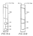
- Level sensing probe 130A is shown in Figs. 3, 6C, and 10. Referring to Fig. 10A, level sensing probe 130A is preferrably a conductivity probe with two exposed pads 178 and 180 with a resistor 182 between them. Reservoir 28 acts as ground. Pads 178 and 180 are placed at the one stick and empty levels. Voltage sensors 174A, 174B, 174C, and 174D are connected between CPU 154 and level sensing probes 130A, 130B, 130C, and 130D, respectively. The voltage sensed changes when pads 178 or 180 becomes exposed.
- the level sensing probes could be printed circuit boards such as board 184 having two thermistors 185 and 186, electrically wired together either in parallel (as shown) or in series.
- the heat loss of thermistors 185 and 186 differs from when they are in air to when they are in ink.
- the resistance of thermistor 185 or 186 changes and is sensed by sensors 174A, 174B, 174C, or 174D1, respectively, which are interfaced between level sensing probes 130A, 130B, 130C, or 130D1, respectively, and CPU 154, as is shown in Fig. 8.
- level sensing is independent of the temperature of operation of the apparatus.
- a film of ink can be sensed around the thermistors prior to the time all of the ink in the reservoir is melted.
- a third thermistor or conductivity pad could be placed in board 184 or probe 130A at the full level to allow CPU 154 to detect overflow.
- FRU 10 is preferably operated at atmospheric pressure and, therefore, venting should be provided.
- air traverses a relatively long path in order to trap impurities. Air travels through vent 188A, chamber 190A, and opening 194A to the dirty or upstream side of filter 24. The air travels downwardly around the rib 70A (shown in dashed lines) of melt chamber 34A, shown in Figs. 1 and 4A. The air then travels through opening 196A of filter 24 and enters the top of compartment 56A.
- Fig. 3 shows an optional filter 200 over vent 188A.
- Figs. 11A-11D show different approaches for connecting siphon plate 114 to front plate 94.
- the siphon plate 114A shown in cross-section, includes legs 212 and 214, which are separated by recess 220A having a generally trapezoidal shape. Recess 220A forms the siphon channel.
- the front surface of legs 212 and 214 is dipped in glue 210 with care being taken to prevent the glue from rising significantly into recess 220A.
- Menisci 224 and 226 of glue 210 protrude into recess 220A, and may significantly affect the siphon channel of recess 220A. It is noted that the dimensions of Fig. 11A-11D have been exaggerated for purposes of illustration.
- Fig. 11B shows a preferred arrangement, in which the siphon channel includes both recess 220A and channel 90A. Menisci 224 and 226 of glue 210 protrude into recess 220A, but do not significantly block siphon channel 90A and recess 220A.
- Fig. 11C illustrates a construction that is similar to that shown in Fig. 11A, except that recess 220A is of rectangular rather than trapezoidal shape. Menisci 224 and 226 of glue 210 protrude into recess 220A and may significantly affect the siphon channel of recess 220A.
- siphon plate 114 is flat, and the siphon path consists of channel 90A. Under the construction of Fig. 11D, glue 210 tends to run into and significantly fill channel 90A.
- Figs. 12A and 12B show filter 24 placed between melt chamber 20 and reservoir 28.
- the ends of walls 49 and 50 and plates 62, 64, 66, and 68 are pressed against the ends of walls 79 and 80 and plates 72, 74, 76, and 78, respectively, with filter 24 separating the walls and plates.
- a rubber seal 226 is molded onto filter 24 to provide a seal between the ends of walls 49 and 50 and plates 62, 64, 66, and 68 and the ends of walls 79 and 80 and plates 72, 74, 76, and 78, respectively.
- a disadvantage of using a rubber seal is that it tends to flow into the screen as shown at areas 230 and 232, thereby and partly blocking filter 24.
- Fig. 12B shows a preferred approach in which beads of a thermoset adhesive 236 are placed on the ends of walls 49, 50, 79, and 80 and plates 62, 64, 66, 68, 72, 74, 76, and 78, where a seal is to be formed.
- thermoset adhesive 236 wicks or flows through the screen to make a seal in which adhesive 236 passes outwardly only slightly from the edges of walls 49, 50, 79, and 80 and plates 62, 64, 66, 68, 72, 74, 76, and 78.
- Adhesive 236 may be of the type called Sylgard manufactured by Dow Corning.
- connector pins and receivers 250, 252, 254, 256, 260, 262, 264, and 266 are used to connect melt chamber 20 to reservoir 28.
- Knobs 280, 282, 284, 286, and 288 are used to connect FRU 10 to the ink jet assembly.
- Knobs 290, 292, 294, and 296 on reservoir 28 may be used to attach head 16 to reservoir 28.
Landscapes
- Ink Jet (AREA)
- Particle Formation And Scattering Control In Inkjet Printers (AREA)
Description
- The present invention relates to a method and an apparatus for melting solid sticks of phase change ink and providing the melted ink to an ink jet head. The invention in its apparatus sense is particularly but not exclusively concerned with field replaceable unit forms of the apparatus ("FRU" hereinafter means field replaceable unit).
- Ink jet printers eject ink onto a print medium, such as paper, in controlled patterns of closely spaced dots. Two commonly used inks are aqueous ink and phase change or hot melt ink. Phase change ink has a liquid phase when it is above the melting temperature, for example 86°C, and a solid phase when it is at or below the melting temperature.
- From US-A-4 791 439 an ink jet apparatus for use with hot melt ink is known, said apparatus having an integrally connected ink jet head and reservoir system, the reservoir system including a highly efficient heat conducting plate, such as aluminium, inserted within an essentially non-heat conducting reservoir housing. The reservoir system has a sloping flow path between an inlet position and a sump from which ink is drawn to the head, and includes a plurality of vanes situated upon the plate for rapid heat transfer.
- Phase change ink is conveniently stored, transported, and inserted into an ink jet printer assembly in solid phase. However, for phase change ink to be properly ejected from a print head, the ink must be in the liquid phase and relatively hot. Because it typically takes a few minutes for phase change ink to melt after heat has been applied to it, there must be a supply of melted ink having the proper temperature for the print head to eject. There is, therefore, a need for a method and an apparatus for melting and storing phase change ink and providing the ink to a print head at the proper temperature.
- An FRU assembly comprises, according to the invention, a melt chamber including multiple subchambers in which sticks of phase change ink are inserted and melted. Melted ink flows through apertures to a reservoir comprising multiple compartments. Each compartment contains a channel and a siphon plate that allow a siphon action that siphons melted ink in the compartments to an orifice that leads to an ink jet print head. Heaters under the control of a CPU melt the ink and keep the melted ink at a desired temperature during various modes of operation.
- It will be appreciated from the following description with reference to the drawings that the invention provides a method and an apparatus for melting and storing phase change ink and providing the ink to a print head at the proper temperature. It will further be appreciated that the invention provides such an apparatus that controllably and automatically regulates the heat applied to the ink.
- Embodiments of the invention will now be described, by way of example only, reference being made to the accompanying drawings in which:-
- Fig. 1 is an exploded isometric frontal view of an ink melt and reservoir assembly, which is an FRU in accordance with the present invention.
- Fig. 2 is an exploded isomemetric back view of the FRU of Fig. 1.
- Fig. 3 is a cross sectional side elevation view of the assembled FRU of Fig. 1.
- Fig. 4A is a front view of the melt chamber.
- Fig. 4B is a top section view of the reservoir.
- Fig. 5 is a schematic fragmentary view of a representative ink jet head.
- Figs. 6A, 6B and 6C show the siphon chamber, siphon plate, and level sensing probe that reside in the reservoir compartments.
- Figs. 7A and 7B show the siphon plate located in the reservoir.
- Fig. 8 is a schematic diagram of the central processing unit used in controlling the FRU.
- Fig. 9 is graph of temperature versus time of various portions of the FRU during different operating modes.
- Fig. 10A shows an ink level sensing probe.
- Fig. 10B shows an alternative ink level sensing probe.
- Figs. 11A, 11B, 11C and 11D show alternative arrangements of the siphon plate and siphon channel.
- Figs. 12A and 12B are cross-sectional fragmentary views showing arrangements for sealing a filter with the melt chamber and reservoir.
- Referring to Figs. 1-3, an
FRU assembly 10 is used by an ink jet printer to receive and melt solid sticks of hot melt ink and provide the melted ink to a multi-orifice ink jet print head assembly 16 ("head 16") affixed toFRU 10. - In a preferred embodiment,
FRU 10 is constructed to be easily inserted as a unit into an ink jet printer assembly of the type described in US Patent Application No 07/633,840 (corresponding to US Patent No 5083143).Head 16 may or may not be considered part of FRU 10. If there is a defect in aparticular FRU 10, then anew FRU 10 may be inserted into the ink jet printer assembly with a minimal amount of downtime. It is for that reason that FRU 10 is referred to as "field replaceable". - FRU 10 is comprised of a
melt chamber 20, a wirecloth mesh filter 24, and areservoir 28. FRU 10 provides melted ink in multiple colors, for example, cyan, yellow, magenta, and black. The ink of each of these colors is physically separated from the ink of the other colors throughoutmelt chamber 20 andreservoir 28. Therefore, for convenience in tracing the travel of the ink, the letter "A" is associated with cyan ink, "B" is associated with yellow ink, "C" is associated with magenta ink, and "D" is associated with black ink. Fig. 3 shows only the portions ofFRU 10 that are used in connection with cyan ink. -
Melt chamber 20 is divided intosubchambers air chambers air chambers 34"), as described below with reference to Fig. 3.Subchamber 30D, which is divided bydivider 44, holds twice as many sticks as the other subchambers because black ink is typically used more frequently than the other colors. - Referring to Fig. 3,
sticks subchamber 30A.Ink stick 38A rests against afloor 46 and amelt plate 48, the latter of which subdivides subchambers 30 fromair chambers 34. Stick 40A rests againststick 38A andplate 48. Ink sticks 38B and 38C (not shown) rest againstfloor 46 andplate 48 insubchambers plate 48. Ink sticks 38D₁ and 38D₂ (not shown), rest againstfloor 46 andplate 48 in subchamber 30D. Ink sticks 40D₁ and 40D₂ rests against sticks 38D₁ and 38D₂ andplate 48.Melt chamber 20 is bounded byside walls -
Melt chamber 20 is preferably formed of a single piece of magnesium, which is light weight and heat conductive.Melt chamber 20 is heated by a resistive-type heater element 52 that causessticks 38A-38D₂ and 40A-40D₂ to melt. In apreferred embodiment heater 52 is a standard 1/4 inch (6.35 millimeters ("mm")) diameter cartridge heater, such as one manufactured by Watlow.Heater 52 is placed next toplate 48 and across the width ofmelt chamber 20. The ends ofheater 52 are shown onside walls thermistor 60 measures the temperature of the surface ofmelt chamber 20 at a convenient location, such as the side ofmelt chamber 20 shown in Fig. 1. - Referring to Figs. 1 and 4A, melted ink flows under the force of gravity from
subchambers apertures 54A, 54B, and 54C toair chambers subchamber 30D to air chambers 34D₁ and 34D₂.Air chambers 34 are separated byplates Ribs - Referring to Figs. 2 and 4B,
reservoir 28 is divided intocompartments plates Reservoir 28 is bounded byside walls filter 24 is placed betweenmelt chamber 20 andreservoir 28.Melt chamber 20 andreservoir 28 are tightly joined together withfilter 24 positioned between them. The ends ofwalls plates walls plates air chambers filter 24, tocompartments air chambers 34 orcompartments 56 does not pass to any of theother air chambers 34 or compartments 56. The exception is that air chambers 56D₁ and 56D₂ are joined to meltchamber 30D and there is an opening at the base ofwall 68 between compartments 56D₁ and 56D₂, so that black ink may flow between compartments 56D₁ and 56D₂. - The appropriate pitch for
filter 24 depends on the diameter of the nozzles inhead 16 and size of particulates in the melted ink. If the melted ink contains a substantial amount of particulates that cannot pass throughfilter 24, then it will become clogged and thereby rapidly lead to poor performance and increased cost for replacement. On the other hand, if the pitch offilter 24 is not small in comparison to the diameter of the nozzles inhead 16, then the nozzles inhead 16 will become clogged relatively fast. It is preferred thathead 16 be made of stainless steel. In a preferred embodiment,filter 24 comprises a Dutch twill woven wire cloth mesh with a 165 x 1400 lay and a pitch of 17 microns. An example of phase change ink usable with the embodiment described herein is found in U.S. Patent No. 4,889,560 of Jaeger, et al., entitled "Phase Change Ink Composition and Phase Change Ink Produced Therefrom," which is assigned to Tektronix, Inc., of Beaverton, Oregon. - Ink in
reservoir 28 is heated primarily by a resistive-type heater element 82, which is coupled tofloor 84 ofreservoir 28, and secondarily by heat frommelt chamber 20. In a preferred embodiment,heater 82 is a cartridge heater of the same type asheater 52 and is placed in a hole beneathfloor 84 that runs across the entire width of reservoir 40 so thatheater 82 is beneath a section of eachcompartment 56. The ends ofheater 82 are shown on each side ofreservoir 28 in Figs. 1 and 2. Athermistor 88 measures the temperature ofreservoir 28 at a convenient location, such as the side ofreservoir 28 shown in Fig. 2. -
Floor 84 is sloped towardsumps 86A (shown in Figs. 3 and 4B) and sumps 86B, 86C, 86D₁, and 86D₂ (shown in Fig. 4B) (collectively "sumps 86").Channels front plate 94 ofreservoir 28 incompartments front plate 94 for convenience of illustration. It may, however, be easier to manufacture the indentations of channels 90 insidefront plate 94, as shown in Fig. 4B, rather than as extensions onfront plate 94 as shown in Fig. 1.Channels sumps 86A, 86B, 86C, 86D₁, and 86D₂ tochambers chambers orifices head 16. Optional filters 134A, 134B, 134C, 134D₁, and 134D₂, similar to filter 24 may be placed in or next tochambers - Fig. 5 shows a schematic view of
nozzles head 16, which is representative of a typical ink jet head. Ink fromorifice 100A entersink chamber 106. Other nozzles (not shown) receive ink from orifices 100. Apiezoceramic material 108 is bonded to adiaphragm 110. An electrical current is applied topiezoceramic material 108. When the current has a particular amplitude and polarity,piezoceramic material 108 bends towardchamber 106 causing ink to be ejected fromnozzle 102 toward aprint medium 112. A low thermal mass ofhead 16, and the thermal isolation betweenhead 16 andreservoir 28 allow a more uniform heating ofhead 16. - Channels 90 span only part of the combined widths of
compartments 56. For example, Fig. 6A showschannel 90A incompartment 56A.Front plate 94 joins withfloor 84 on both sides ofchannel 90A atsections - Siphon
plates 114A, 114B, 114C, 114D₁, and 114D₂ (collectively "siphon plates 114") are positioned adjacent tochannels plate 114A overplate 94, andchannel 90A andsump 86A (shown in dashed lines). Ink is siphoned fromsumps 86A, 86B, 86C, 86D₁, and 86D₂ throughchannels chambers - The siphon action is created by a difference in pressure between
chamber 106 andchannel 90A following an ejection of ink fromnozzle 102 inhead 16. If siphon plates 114 are positioned too close tofront plate 94, there will be capillary action, which may be undesirable because it can lead to ink drooling out ofnozzle 102. A preferred embodiment of siphon plates 114 is illustrated by siphonplate 114A, shown in Figs. 7A and 7B. Siphonplate 114A is comprised oflegs inside plate 128, and anouter layer 140. Insideplate 128 is inset about 0.130 inch (3.30 mm) fromsurface 132 which is sealed tofront plate 94.Outer layer 140 slopes outwardly at a 4° angle with respect toinside plate 128 andsurface 132. - Referring to Fig. 3, drooling of ink may also be caused if the surface of the ink in
compartment 56A is too close to the height ofnozzle 102. The distance fromnozzle 102 to the bottom ofsump 86A is denominated "X." The distance fromnozzle 102 to the full level is denominated "Y." In a preferred embodiment, X = 2.1 inches (53.3 mm) and Y = 1.0 inches (25.4 mm). If Y is less than zero (i.e., the level of the surface of the ink is higher than nozzle 102), there will probably be drooling of ink fromnozzle 102. In addition, if Y is much less than 1.0 inches (25.4 mm), there also may be drooling or other undesirable effects. - Figs. 3, 6B-6C, and 10B, show the position of siphon
plate 114A. In Fig. 6B, the positions ofsump 86A,channel 90A, andchamber 98A are shown in dashed lines.Abutments level sensing probe 130A, shown in Fig. 6C, to siphonplate 114A.Brackets 136 and 138 are used to restrict the movement of ink aroundlevel sensing probe 130A to increase the accuracy of the level readings. - Level sensing probes 130A, 130B, 130C, which are attached to siphon
plates 114A, 114B, and 114C, respectively, sense the level of ink withincompartments wall 68, so that level sensing probe 130D measures the level of ink in both compartments. The tops of level sensing probes 130A, 130B, 130C, and 130D₁ (collectively "level sensing probes 130") are shown in Fig. 1. - Referring to Fig. 8, level sensing probes 130 signal a central processing unit ("CPU") 154 or other electronics of the ink jet printer assembly to indicate certain information at a human interface unit, e.g., a liquid crystal display ("LCD") 156 or light emitting diodes (not shown). The information includes: (a) whether
compartment compartments subchamber - A resistive-
type heater 142, shown schematically as a resistor, is used to maintain the temperature ofhead 16, and thus of the temperature the ink withinhead 16.Heater 142 may be a cartridge heater of the same type asheaters heater 142 is usually sufficient, although multiple heaters could be used. Athermistor 146, attached to head 16, is used to measure the temperature ofhead 16. - Fig. 9 illustrates the temperature profile of
FRU 10. The temperature profile includes the temperatures TM (of melt chamber 20), TR (of reservoir 28), and TH (of head 16) as a function of time (in minutes) during various modes of operation. Temperatures TM, TR, and TH are measured by therespective thermistors
TM is the temperature ofmelt chamber 20;
TR is the temperature ofreservoir 28;
TH is the temperature ofhead 16;
TP is the value of TH during printing;
TSi is an initial maximum temperature of TR during the start-up mode;
TS is the ink supply temperature, i.e., the temperature TM from time t₆ to shut down mode;
In a first embodiment, following ready mode, TR decreases from TS to temperature TI and remains at TI until head heating mode, and TH decreases from TP to TI remains at TI until head heating mode;
In a second embodiment, TR decreases from temperature TSi to temperature TS following start-up mode, and remains equal to temperature TS until shut down mode, and TH decreases from TP to temperature TS following ready mode, and remains at TS until head heating mode;
TMP is the temperature at which ink melts;
TA is the ambient room temperature;
tsmin is the minimum expected start-up time; and
tsmax is the maximum expected start-up time. - Preferred values are TP = 150°C, TSi = 130°C, TS = 110°C, TI = 95°C, TMP = 86°C, and TA = 25 to 30°C.
- The modes of operation of
FRU 10 include startup, ready, non-use ready, idle (or standby), head heating, and shut down. Ready mode includes a printing submode and a non-use ready submode. The modes of operation are defined in terms of the temperature ofthermistors heaters heaters heaters - Fig. 8 shows
CPU 154, which is interfaced toheaters thermistors off switch 176, a MacIntosh computer 180 (manufactured by Apple Computer Co. of Cupertino, California), the piezoceramic material ofhead 16, andLCD 156.Heaters drivers thermistors CPU 154 receives print commands from MacIntosh 180 (or another device that can issue print commands).LCD 156 is controlled byCPU 154 throughLCD driver 158.LCD 156 displays the information described above and other information such as the ink jet printer is out of paper or malfunctioning. - As used herein with respect to Fig. 9, time


- Referring to Fig. 9, at time t₀, a user activates on-
off switch 176 and start-up mode begins. At time t₀,
melt chamber 20,reservoir 28, andhead assembly 16 are in the solid phase. Shortly after time t₀,CPU 154 activatesheaters plate 48 is primarily controlled byheater 52. From time t₀ to time t₆, TM increases from TA to TS, as shown in Fig. 9, which causes some ink to melt and flow through apertures 54.CPU 154 keeps TM at about 110°C until shut down mode by turningheater 52 on and off as needed.CPU 154 uses the temperature fromthermistor 60 to determine whenheater 52 should be turned on and off. Alternatively, from time t₀ to time t₈,CPU 154 may directheater 52 to raise TM to follow the same heat curve as TR, discussed below and shown in Fig. 9. - At time t₀,
heater 82 is turned on. From time t₀ to time t₄, TR increases from TA to TSi. From time t₄ to the end of start-up mode at time t₈,CPU 154 uses the temperature ofthermistor 88 to determine when to turnheater 82 on and off to keep TR equal to about TSi. Following start-up mode, TR decreases to TS during ready mode. In the first embodiment, TR remains at TS until the end of ready mode, at which time TR decreases to TI. During head heating mode, TR increases back to TS and stays at TS until the end of ready mode. In the second embodiment, TR remains at TS from the first occurrence of ready mode until shut-down mode. The purpose of initially raising the temperature of the ink inreservoir 28 to TSi is to accelerate the melting of ink that may have solidified inreservoir 28. A reason to lower TR to TS or TI during ready, idle, and head heating modes is to reduce the probability of ink degradation caused by excessive heat over a prolonged period of time. - From time t₀ to about time t₄, ink in
head 16 is heated by heat fromreservoir 28 and TH increases from tA to about 70°C. At time t₄,CPU 154 turns onheater 142. From time t₄ to about time t₆, the temperature TH ofhead 16 is raised until it reaches TP. By raising TH in several steps, priming ofhead 16 tends to be maintained because the melted ink inreservoir 28 tends to expand intohead 16 before the solidified ink inhead 16 melts. Ifhead 16 were heated at a faster rate from time t₀ to about time t₄, ink inhead 16 would tend to be forced out of nozzles such asnozzle 102, which could result in air being drawn into the nozzles and cause problems in printing. - The expected first time ("time tactual") at which


CPU 154 switches from startup mode to ready mode. (Although in Fig. 9, this does not happen until time tsmax for illustrative purposes. ) A print command is given fromMacIntosh 180 prior to or immediately following time tactual. Therefore,CPU 154 causes head 16 to begin printing at the beginning of the ready mode. Alternatively, the first print command could be given after the beginning of ready mode. - During the printing mode of operation,
CPU 154 uses the temperature ofthermistor 146 to maintain
- At time t₉ (note that time t₉ is not equal to t₀ + nine minutes), printing is concluded, and
CPU 154 switches to non-use ready mode. Following a period of non-use ready, the printer is placed in an idle or stand-by mode at time t₁₀. At time t₁₁, a print command is received byCPU 154, and it switches from idle mode to head heating mode, during which TH is increased from TI or TS to TP. TR increases to or remains at TS. - During shut-down of the apparatus, the temperatures TM, TR and TH are allowed to drop as shown in Fig. 9. The temperature TH drops somewhat faster than the temperature TR and TM so that, as ink solidifies in
head 16, the liquid ink from reservoir tends to fillhead 16 as ink inhead 16 contracts during solidification. - Because TS and TI are greater than TMP, the ink in
reservoir 28 is always melted during ready, non-use ready, and idle modes. Consequently, there is no need to wait for remelting of ink inreservoir 28 prior to printing and following a stand-by mode. Because the ink does not solidify,head 16 does not have to be purged after idle mode. - With the above-described temperature profile, not all of the ink in the reservoir needs to be melted before starting ready mode. The
heads 16 may be ready to eject ink as soon as a fluid film forms around a block of ink inreservoir 28. Consequently, a warm-up time of six to eight minutes is typically all that is required before printing can start. Depending on the type of ink and dimensions ofFRU 10, the time required before printing can start may be shorter than six minutes. - In a preferred embodiment, melt
chamber 20 is about 4 inches (101.6 mm) wide (i.e., from 34A to 34D₂), 5 inches tall (127.0 mm), and 1 inch deep (25.4 mm).Reservoir 28 is about 4 inches (101.6 mm) wide, 5 inches (127.0 mm) tall, and 3 1/2 inches (88.9 mm) deep atfloor 84.Reservoir 28 accommodates about 150 grams of ink.Floor 84 and the section ofreservoir 28 that attaches to filter 24 form an angle ϑ (shown in Fig. 1), wherefloor 84 is parallel to the surface of the earth. The angle ϑ is preferrably in the range 40° ≦ ϑ ≦ 90°, with about 60° being preferred because it is easier to put sticks of ink intomelt chamber 20 if it is sloping at about 60°.Filter 24 should be vertically oriented. If the angle ϑ were close to 0°, there would be a tendency forfilter 24 to clog because a horizontal filter screen tends to become wet with ink, thereby making it more difficult for air to pass throughfilter 24. -
Compartments 56 are much taller than they are wide. Consequently, whenFRU 10 is shuttled (reciprocated) across the surface of the ink jet drum during printing, less sloshing of the ink occurs whenFRU 10 reverses direction. This is advantageous for at least two reasons: (a) it is easier to sense the actual level of ink incompartments 56; and (b) it reduces dynamic accelerations of the ink during the shuttling operation, which can affect the desired uniform shuttling speed during printing and ink dot placement on the media. -
Level sensing probe 130A is shown in Figs. 3, 6C, and 10. Referring to Fig. 10A,level sensing probe 130A is preferrably a conductivity probe with two exposedpads resistor 182 between them.Reservoir 28 acts as ground.Pads Voltage sensors CPU 154 and level sensing probes 130A, 130B, 130C, and 130D, respectively. The voltage sensed changes whenpads - Alternatively, referring to Fig. 10B, the level sensing probes could be printed circuit boards such as
board 184 having twothermistors thermistors thermistor sensors CPU 154, as is shown in Fig. 8. As a consequence, level sensing is independent of the temperature of operation of the apparatus. A film of ink can be sensed around the thermistors prior to the time all of the ink in the reservoir is melted. A third thermistor or conductivity pad could be placed inboard 184 or probe 130A at the full level to allowCPU 154 to detect overflow. -
FRU 10 is preferably operated at atmospheric pressure and, therefore, venting should be provided. As shown in Fig. 2, air traverses a relatively long path in order to trap impurities. Air travels throughvent 188A,chamber 190A, and opening 194A to the dirty or upstream side offilter 24. The air travels downwardly around therib 70A (shown in dashed lines) ofmelt chamber 34A, shown in Figs. 1 and 4A. The air then travels throughopening 196A offilter 24 and enters the top ofcompartment 56A. Fig. 3 shows anoptional filter 200 overvent 188A. - Figs. 11A-11D show different approaches for connecting siphon plate 114 to
front plate 94. In Fig. 11A there is nochannel 90A. The siphonplate 114A, shown in cross-section, includeslegs recess 220A having a generally trapezoidal shape.Recess 220A forms the siphon channel. To secureplate 114A in place, the front surface oflegs glue 210 with care being taken to prevent the glue from rising significantly intorecess 220A.Menisci glue 210 protrude intorecess 220A, and may significantly affect the siphon channel ofrecess 220A. It is noted that the dimensions of Fig. 11A-11D have been exaggerated for purposes of illustration. - Fig. 11B shows a preferred arrangement, in which the siphon channel includes both
recess 220A andchannel 90A.Menisci glue 210 protrude intorecess 220A, but do not significantly block siphonchannel 90A andrecess 220A. Fig. 11C illustrates a construction that is similar to that shown in Fig. 11A, except thatrecess 220A is of rectangular rather than trapezoidal shape.Menisci glue 210 protrude intorecess 220A and may significantly affect the siphon channel ofrecess 220A. In Fig. 11D, siphon plate 114 is flat, and the siphon path consists ofchannel 90A. Under the construction of Fig. 11D,glue 210 tends to run into and significantly fillchannel 90A. - Figs. 12A and 12B show
filter 24 placed betweenmelt chamber 20 andreservoir 28. To prevent ink from weeping betweenmelt chamber 20 andreservoir 28, the ends ofwalls plates walls plates filter 24 separating the walls and plates. In Fig. 12A, arubber seal 226 is molded ontofilter 24 to provide a seal between the ends ofwalls plates walls plates filter 24. - Fig. 12B shows a preferred approach in which beads of a
thermoset adhesive 236 are placed on the ends ofwalls plates thermoset adhesive 236 wicks or flows through the screen to make a seal in which adhesive 236 passes outwardly only slightly from the edges ofwalls plates - Referring to Figs. 1 and 2, connector pins and
receivers melt chamber 20 toreservoir 28.Knobs FRU 10 to the ink jet assembly.Knobs reservoir 28 may be used to attachhead 16 toreservoir 28. - It will be obvious to those having skill in the art that many changes may be made in the above-described details of the preferred embodiment of the present invention without departing from the underlying principles thereof.
Claims (10)
- An assembly for inclusion in an ink jet printer for melting and storing phase change ink and providing the ink at approximately a first predetermined temperature to a print head of said ink jet printer, the assembly having a ready mode during which printing may occur and an idle mode during which printing may not occur, the assembly comprising a melt chamber comprising means for supporting a stick of solid phase change ink; melt chamber heat measuring and applying means for measuring heat of the melt chamber and applying sufficient heat to the melt chamber to melt the stick of phase change ink; a reservoir operationally connected to the melt chamber such that the melted ink in the melt chamber freely flows to the reservoir under the force of gravity; a filter between the melt chamber and the reservoir; reservoir heat measuring and applying means for measuring heat of the reservoir and applying sufficient heat to the reservoir to maintain the melted ink in the reservoir at approximately a second predetermined temperature at least during substantially all of the ready mode; siphon means for siphoning a portion of the melted ink in the reservoir to an orifice which is operationally connected to the print head; and print head heat measuring and applying means for measuring heat of the print head and applying sufficient heat to the print head to maintain the print head at approximately the first predetermined temperature during substantially all of the ready mode, and substantially reducing the heat of the ink in the print head during the idle mode.
- An assembly as claimed in Claim 1 in which the reservoir includes a floor and the melt chamber is positioned so the stick of ink is inserted at an angle ϑ with respect to the floor of the reservoir, where 50° ≦ ϑ ≦ 70°.
- An assembly as claimed in Claim 1 or Claim 2 in which the reservoir includes a floor which is parallel to the surface of the earth and the melt chamber is positioned so the stick of ink is inserted at an angle ϑ with respect to the floor of the reservoir, where 50° ≦ ϑ ≦ 70°.
- An assembly as claimed in Claim 2 or Claim 3 in which the melt chamber is positioned so the stick of ink is inserted at an angle of approximately 60° with respect to the floor of the reservoir.
- An assembly as claimed in any preceding claim and including level sensing means for sensing level of the ink in the reservoir, the level sensing means including two conductivity pads separated by a resistor.
- An assembly as claimed in any preceding claim in which the melt chamber and reservoir are joined through the filter by a thermoset adhesive.
- An assembly as claimed in any preceding claim in which the siphon means comprises a channel in a wall of the reservoir and a plate secured over the channel.
- An assembly as claimed in any preceding claim and including an air path between the melt chamber and the reservoir.
- A method of operating an ink jet printer which method comprises supporting a body of solid phase change ink within an ink melt chamber, applying heat to said body of solid ink therein to melt said solid ink to form liquid ink, said liquid ink passing to a liquid ink reservoir disposed to receive output from said melt chamber, applying heat to said liquid ink in said reservoir to maintain a predetermined reservoir liquid ink temperature preferably higher than that of the liquid ink in the melt chamber during all printer ready mode states, transferring liquid ink to a print head of the ink jet printer, applying heat to said liquid ink in said print head to maintain a predetermined print head liquid ink temperature preferably higher than that of the liquid ink in the melt chamber and the ink reservoir during all printer ready mode states, and ejecting a drop of said liquid phase change ink from the print head to a print substrate.
- A method as claimed in Claim 9 in which the temperature of the ink in the reservoir during printer idle mode is substantially the same as in printer ready mode.
Applications Claiming Priority (2)
| Application Number | Priority Date | Filing Date | Title |
|---|---|---|---|
| US67423291A | 1991-03-25 | 1991-03-25 | |
| US674232 | 1991-03-25 |
Publications (2)
| Publication Number | Publication Date |
|---|---|
| EP0506403A1 EP0506403A1 (en) | 1992-09-30 |
| EP0506403B1 true EP0506403B1 (en) | 1995-08-23 |
Family
ID=24705843
Family Applications (1)
| Application Number | Title | Priority Date | Filing Date |
|---|---|---|---|
| EP92302632A Expired - Lifetime EP0506403B1 (en) | 1991-03-25 | 1992-03-25 | Method and apparatus for providing phase change ink to an ink jet printer |
Country Status (4)
| Country | Link |
|---|---|
| US (2) | US5276468A (en) |
| EP (1) | EP0506403B1 (en) |
| JP (1) | JP2663077B2 (en) |
| DE (1) | DE69204191T2 (en) |
Families Citing this family (91)
| Publication number | Priority date | Publication date | Assignee | Title |
|---|---|---|---|---|
| US5424767A (en) * | 1993-03-02 | 1995-06-13 | Tektronix, Inc. | Apparatus and method for heating ink to a uniform temperature in a multiple-orifice phase-change ink-jet print head |
| US5920332A (en) * | 1993-05-04 | 1999-07-06 | Markem Corporation | Ink barrier for fluid reservoir vacuum or pressure line |
| US5489925A (en) * | 1993-05-04 | 1996-02-06 | Markem Corporation | Ink jet printing system |
| GB2297726B (en) * | 1993-05-04 | 1997-02-19 | Markem Corp | Ink jet printing system |
| US5428376A (en) * | 1993-10-29 | 1995-06-27 | Hewlett-Packard Company | Thermal turn on energy test for an inkjet printer |
| JP3184737B2 (en) * | 1994-05-27 | 2001-07-09 | キヤノン株式会社 | Recording head, recording head unit, ink tank, and ink jet recording apparatus having the recording head |
| US5646663A (en) * | 1994-09-16 | 1997-07-08 | Videojet Systems International, Inc. | Method and apparatus for continuous ink jet printing with a non-sinusoidal driving waveform |
| US5510821B1 (en) * | 1994-09-20 | 2000-05-02 | Tektronix Inc | Solid ink stick |
| US5742313A (en) * | 1994-10-31 | 1998-04-21 | Spectra, Inc. | Efficient ink jet head arrangement |
| US5598200A (en) * | 1995-01-26 | 1997-01-28 | Gore; David W. | Method and apparatus for producing a discrete droplet of high temperature liquid |
| US5630510A (en) * | 1995-09-07 | 1997-05-20 | Polaroid Corporation | Packaging and loading solid ink nuggets for ink jet apparatus |
| JPH09141846A (en) * | 1995-11-20 | 1997-06-03 | Brother Ind Ltd | Hot melt type inkjet printer |
| JPH09141898A (en) * | 1995-11-20 | 1997-06-03 | Brother Ind Ltd | Inkjet printer |
| US5793398A (en) * | 1995-11-29 | 1998-08-11 | Levi Strauss & Co. | Hot melt ink jet shademarking system for use with automatic fabric spreading apparatus |
| US5997121A (en) | 1995-12-14 | 1999-12-07 | Xerox Corporation | Sensing system for detecting presence of an ink container and level of ink therein |
| US5731824A (en) * | 1995-12-18 | 1998-03-24 | Xerox Corporation | Ink level sensing system for an ink jet printer |
| US5682184A (en) * | 1995-12-18 | 1997-10-28 | Xerox Corporation | System for sensing ink level and type of ink for an ink jet printer |
| US5784089A (en) * | 1996-03-07 | 1998-07-21 | Tektronix, Inc. | Melt plate design for a solid ink printer |
| US6057399A (en) * | 1996-06-28 | 2000-05-02 | Xerox Corporation | Isocyanate-derived phase change ink additive for improved electronic level sensing reliability and type encoding |
| US5753360A (en) * | 1996-07-12 | 1998-05-19 | Sterling Diagnostic Imaging, Inc. | Medium for phase change ink printing |
| EP0820873A3 (en) * | 1996-07-24 | 1999-01-07 | Brother Kogyo Kabushiki Kaisha | Ink supplying apparatus |
| US6086700A (en) * | 1996-09-05 | 2000-07-11 | Agfa-Gevaert N.V. | Transparent media for phase change ink printing |
| US5756226A (en) * | 1996-09-05 | 1998-05-26 | Sterling Diagnostic Imaging, Inc. | Transparent media for phase change ink printing |
| US5917528A (en) * | 1996-09-05 | 1999-06-29 | Tektronix, Inc. | Solid ink stick supply apparatus and method |
| US6007173A (en) * | 1996-09-26 | 1999-12-28 | Xerox Corporation | Ink status system for a liquid ink printer |
| US5754209A (en) * | 1996-11-01 | 1998-05-19 | Sterling Diagnostic Imaging, Inc. | Printing method for producing gradient images |
| JPH10146962A (en) * | 1996-11-15 | 1998-06-02 | Brother Ind Ltd | Hot melt inkjet printer head |
| EP0951395A1 (en) * | 1997-01-09 | 1999-10-27 | Domino Printing Sciences Plc | Ink cartridge for an ink jet printer |
| US6109803A (en) * | 1997-02-13 | 2000-08-29 | Brother Kogyo Kabushiki Kaisha | Information recording method and printer |
| US6089686A (en) * | 1997-05-28 | 2000-07-18 | Xerox Corporation | Method for supplying ink to an ink jet printer |
| US6180255B1 (en) | 1998-02-05 | 2001-01-30 | Agfa Gevaert N.V. | Structured media for phase change ink printing |
| US6260940B1 (en) * | 1998-05-04 | 2001-07-17 | Canon Kabushiki Kaisha | Ink jet printing system having ink preheating during non-printing periods |
| US6155664A (en) * | 1998-06-19 | 2000-12-05 | Lexmark International, Inc. | Off-carrier inkjet print supply with memory |
| US6099956A (en) * | 1998-07-17 | 2000-08-08 | Agfa Corporation | Recording medium |
| US6001160A (en) * | 1998-09-04 | 1999-12-14 | Tektronix, Inc. | Phase change ink additive for improved electronic level sensing reliability and type encoding |
| US6390582B1 (en) | 1998-10-13 | 2002-05-21 | Xerox Corporation | Method for reducing thermal aging in an ink jet print head |
| US6258451B1 (en) | 1998-11-20 | 2001-07-10 | Agfa Gevaert N.V. | Recording medium |
| US20020105668A1 (en) * | 1999-01-20 | 2002-08-08 | Lilland Kevin R. | Print consumables monitoring |
| US7213989B2 (en) * | 2000-05-23 | 2007-05-08 | Silverbrook Research Pty Ltd | Ink distribution structure for a printhead |
| US6488422B1 (en) | 2000-05-23 | 2002-12-03 | Silverbrook Research Pty Ltd | Paper thickness sensor in a printer |
| US6988840B2 (en) * | 2000-05-23 | 2006-01-24 | Silverbrook Research Pty Ltd | Printhead chassis assembly |
| US7004652B2 (en) * | 2000-05-23 | 2006-02-28 | Silverbrook Research Pty Ltd | Printer for accommodating varying page thickness |
| US6786658B2 (en) * | 2000-05-23 | 2004-09-07 | Silverbrook Research Pty. Ltd. | Printer for accommodating varying page thicknesses |
| DE60023952T2 (en) * | 2000-05-24 | 2006-12-07 | Silverbrook Research Pty. Ltd. | SENSOR FOR PAPER THICKNESS IN A PRINTER |
| KR20030007755A (en) * | 2000-05-31 | 2003-01-23 | 허니웰 인터내셔날 인코포레이티드 | Filling device |
| US6485135B1 (en) * | 2000-10-20 | 2002-11-26 | Silverbrook Research Pty Ltd | Ink feed for six color inkjet modular printhead |
| AU2004203199B2 (en) * | 2000-10-20 | 2005-07-21 | Memjet Technology Limited | An ink supply assembly |
| US6626513B2 (en) | 2001-07-18 | 2003-09-30 | Lexmark International, Inc. | Ink detection circuit and sensor for an ink jet printer |
| US7296259B2 (en) * | 2002-09-11 | 2007-11-13 | Agere Systems Inc. | Processor system with cache-based software breakpoints |
| US6824241B2 (en) * | 2002-12-16 | 2004-11-30 | Xerox Corporation | Ink jet apparatus |
| US6905201B2 (en) * | 2002-12-16 | 2005-06-14 | Xerox Corporation | Solid phase change ink melter assembly and phase change ink image producing machine having same |
| US6866375B2 (en) * | 2002-12-16 | 2005-03-15 | Xerox Corporation | Solid phase change ink melter assembly and phase change ink image producing machine having same |
| US6966222B2 (en) * | 2003-12-08 | 2005-11-22 | Hewlett-Packard Development Company, L.P. | Methods and apparatus for media level measurement |
| US7210773B2 (en) * | 2003-12-16 | 2007-05-01 | Xerox Corporation | Ink loader melt plate assembly |
| US6981754B2 (en) * | 2003-12-30 | 2006-01-03 | Xerox Corporation | Ink delivery and printing method for phasing printing systems |
| US7234787B2 (en) * | 2004-01-08 | 2007-06-26 | Eastman Kodak Company | Liquid level detection method and apparatus |
| US7063410B2 (en) * | 2004-02-25 | 2006-06-20 | Xerox Corporation | Ink jet apparatus |
| US7207668B2 (en) * | 2004-03-22 | 2007-04-24 | Xerox Corporation | Ink supply container for high speed solid ink printers |
| US7503648B2 (en) * | 2005-06-09 | 2009-03-17 | Xerox Corporation | Ink consumption determination |
| WO2007007816A1 (en) * | 2005-07-08 | 2007-01-18 | Canon Kabushiki Kaisha | Inkjet recording device and method of detecting remaining amount of ink |
| KR100717038B1 (en) * | 2005-10-10 | 2007-05-10 | 삼성전자주식회사 | Ink property measuring apparatus, ink jet printer comprising the same, and ink state sensing method |
| JP2007182075A (en) * | 2006-01-05 | 2007-07-19 | Oce Technologies Bv | Printer, and method for controlling the printer |
| US7581827B2 (en) * | 2006-04-26 | 2009-09-01 | Xerox Corporation | System and method for melting solid ink sticks in a phase change ink printer |
| US20070252879A1 (en) * | 2006-04-28 | 2007-11-01 | Xerox Corporation | Phase change ink additives |
| US7794072B2 (en) * | 2006-11-21 | 2010-09-14 | Xerox Corporation | Guide for printer solid ink transport and method |
| US7651210B2 (en) * | 2006-11-21 | 2010-01-26 | Xerox Corporation | Transport system for solid ink for cooperation with melt head in a printer |
| US7883195B2 (en) * | 2006-11-21 | 2011-02-08 | Xerox Corporation | Solid ink stick features for printer ink transport and method |
| US7976144B2 (en) * | 2006-11-21 | 2011-07-12 | Xerox Corporation | System and method for delivering solid ink sticks to a melting device through a non-linear guide |
| US7798624B2 (en) * | 2006-11-21 | 2010-09-21 | Xerox Corporation | Transport system for solid ink in a printer |
| EP1980925B1 (en) * | 2007-04-13 | 2013-12-18 | Océ-Technologies B.V. | Method and control unit for controlling the power supplied to a plurality of heat sources in a printer |
| US7976118B2 (en) * | 2007-10-22 | 2011-07-12 | Xerox Corporation | Transport system for providing a continuous supply of solid ink to a melting assembly in a printer |
| US7887173B2 (en) | 2008-01-18 | 2011-02-15 | Xerox Corporation | Transport system having multiple moving forces for solid ink delivery in a printer |
| US8052264B2 (en) * | 2008-03-26 | 2011-11-08 | Xerox Corporation | Melting device for increased production of melted ink in a solid ink printer |
| WO2010056243A1 (en) * | 2008-11-13 | 2010-05-20 | Hewlett-Packard Development Company, L.P. | Conductivity sensor with cleaning apparatus |
| US8079691B2 (en) * | 2009-02-09 | 2011-12-20 | Xerox Corporation | Foam plate for reducing foam in a printhead |
| US20100208017A1 (en) * | 2009-02-19 | 2010-08-19 | Black Dot Technology, Inc. | Imaging module for hot melt wax ink jet printer |
| US8366254B2 (en) * | 2009-03-26 | 2013-02-05 | Xerox Corporation | Method and apparatus for melt cessation to limit ink flow and ink stick deformation |
| US8128188B2 (en) * | 2009-04-30 | 2012-03-06 | Hewlett-Packard Development Company, L.P. | Monitoring ink flow |
| US8201928B2 (en) * | 2009-12-15 | 2012-06-19 | Xerox Corporation | Inkjet ejector having an improved filter |
| US8562091B2 (en) * | 2010-03-09 | 2013-10-22 | Xerox Corporation | Apparatus and method for detecting ink in a reservoir using an overdriven thermistor and an electrical conductor extending from the thermistor |
| US8240830B2 (en) * | 2010-03-10 | 2012-08-14 | Xerox Corporation | No spill, feed controlled removable container for delivering pelletized substances |
| US8506063B2 (en) | 2011-02-07 | 2013-08-13 | Palo Alto Research Center Incorporated | Coordination of pressure and temperature during ink phase change |
| US8556372B2 (en) | 2011-02-07 | 2013-10-15 | Palo Alto Research Center Incorporated | Cooling rate and thermal gradient control to reduce bubbles and voids in phase change ink |
| US20120200630A1 (en) * | 2011-02-07 | 2012-08-09 | Palo Alto Research Center Incorporated | Reduction of bubbles and voids in phase change ink |
| US8562117B2 (en) | 2011-02-07 | 2013-10-22 | Palo Alto Research Center Incorporated | Pressure pulses to reduce bubbles and voids in phase change ink |
| US8696098B2 (en) * | 2011-12-09 | 2014-04-15 | Xerox Corporation | Printhead having particle circulation with separation |
| JP6387694B2 (en) | 2014-06-12 | 2018-09-12 | ブラザー工業株式会社 | tank |
| US11597206B2 (en) | 2018-03-12 | 2023-03-07 | Hewlett-Packard Development Company, L.P. | Purging manifolds |
| JP7367324B2 (en) * | 2019-03-29 | 2023-10-24 | ブラザー工業株式会社 | image recording device |
| US11618086B2 (en) | 2020-12-22 | 2023-04-04 | Xerox Corporation | Removable inner shell for dross control and/or removal for metal printer |
| US11858276B2 (en) * | 2020-12-22 | 2024-01-02 | Additive Technologies, LLC | Resistive liquid metal level sensing in a magnetohydrodynamic (MHD) jetting system |
Family Cites Families (17)
| Publication number | Priority date | Publication date | Assignee | Title |
|---|---|---|---|---|
| DE3428434C2 (en) * | 1983-08-02 | 1995-09-14 | Canon Kk | Printing device |
| US4667206A (en) * | 1984-10-15 | 1987-05-19 | Deyoung Thomas W | Ink jet apparatus and method of operating the ink jet apparatus wherein phase change ink is supplied in solid-state form |
| US4658274A (en) * | 1984-10-16 | 1987-04-14 | Exxon Printing Systems, Inc. | Melt ink jet apparatus with means and method for repriming |
| US4631557B1 (en) * | 1984-10-15 | 1997-12-16 | Data Products Corp | Ink jet employing phase change ink and method of operation |
| US4593292A (en) * | 1984-10-15 | 1986-06-03 | Exxon Research And Engineering Co. | Ink jet apparatus and method of operating ink jet apparatus employing phase change ink melted as needed |
| US4609924A (en) * | 1984-10-15 | 1986-09-02 | Exxon Printing Systems, Inc. | Buffer reservoir for ink jet apparatus and method |
| US4607266A (en) * | 1984-10-15 | 1986-08-19 | Debonte William J | Phase change ink jet with independent heating of jet and reservoir |
| JPS61135751A (en) * | 1984-10-16 | 1986-06-23 | データプロダクツ コーポレイション | Phase conversion ink injector |
| US4580147A (en) * | 1984-10-16 | 1986-04-01 | Exxon Research And Engineering Co. | Ink jet apparatus with improved reservoir system for handling hot melt ink |
| US4742364A (en) * | 1984-10-16 | 1988-05-03 | Dataproducts Corporation | Ink jet apparatus and method employing phase change ink |
| US4873539A (en) * | 1984-10-16 | 1989-10-10 | Dataproducts Corporation | Phase change ink jet apparatus |
| US4682187A (en) * | 1984-11-08 | 1987-07-21 | Martner John G | Ink jet method and apparatus utilizing grandular or hot melt ink |
| US4719475A (en) * | 1985-04-10 | 1988-01-12 | Canon Kabushiki Kaisha | Ink-jet recording apparatus and ink tank used therein |
| JPS62117750A (en) * | 1985-11-18 | 1987-05-29 | Seiko Epson Corp | Ink jet recording method |
| US4791439A (en) * | 1986-07-15 | 1988-12-13 | Dataproducts Corporation | Ink jet apparatus with improved reservoir system for handling hot melt ink |
| US4814786A (en) * | 1987-04-28 | 1989-03-21 | Spectra, Inc. | Hot melt ink supply system |
| US4791438A (en) * | 1987-10-28 | 1988-12-13 | Hewlett-Packard Company | Balanced capillary ink jet pen for ink jet printing systems |
-
1992
- 1992-03-25 EP EP92302632A patent/EP0506403B1/en not_active Expired - Lifetime
- 1992-03-25 DE DE69204191T patent/DE69204191T2/en not_active Expired - Fee Related
- 1992-03-25 JP JP4098681A patent/JP2663077B2/en not_active Expired - Fee Related
- 1992-10-23 US US07/965,812 patent/US5276468A/en not_active Expired - Lifetime
-
1993
- 1993-04-26 US US08/034,915 patent/US5386224A/en not_active Expired - Lifetime
Also Published As
| Publication number | Publication date |
|---|---|
| DE69204191D1 (en) | 1995-09-28 |
| EP0506403A1 (en) | 1992-09-30 |
| DE69204191T2 (en) | 1996-01-25 |
| JPH05169644A (en) | 1993-07-09 |
| US5386224A (en) | 1995-01-31 |
| JP2663077B2 (en) | 1997-10-15 |
| US5276468A (en) | 1994-01-04 |
Similar Documents
| Publication | Publication Date | Title |
|---|---|---|
| EP0506403A1 (en) | Method and apparatus for providing phase change ink to an ink jet printer | |
| US5576745A (en) | Recording apparatus having thermal head and recording method | |
| US5179389A (en) | Ink jet recording with head driving condition regulation | |
| US6007173A (en) | Ink status system for a liquid ink printer | |
| KR100926412B1 (en) | Replaceable ink containers, how the printing system works, and how to make replacement ink containers | |
| KR940010874B1 (en) | Improved ink quality detecting device and recording apparatus with the device | |
| US4998120A (en) | Hot melt ink jet printing apparatus | |
| US6394571B1 (en) | Method and apparatus for controlling printing operation with externally supplied parameters | |
| EP0626265B1 (en) | Ink jet recording apparatus controlled by presumed temperature and method therefor | |
| JPH04292952A (en) | Ink jet printer with ink supply monitor means | |
| JPH06320732A (en) | Inkjet recording device | |
| JP3020963B2 (en) | ink cartridge | |
| EP3747658B1 (en) | Inkjet printing system and method for controlling inkjet printing system | |
| US5975669A (en) | Ink-jet recording apparatus and recording method | |
| JP2877971B2 (en) | Ink jet recording device | |
| EP0692385B1 (en) | Liquid discharging recording head | |
| EP0370765B1 (en) | Ink jet head cartridge with a residual-ink detector | |
| EP1022139B1 (en) | Ink jet printers | |
| JP3155838B2 (en) | Ink jet recording device | |
| JP3263248B2 (en) | Printing apparatus and printing method | |
| JPH09169123A (en) | ink cartridge | |
| JPH0880619A (en) | INKJET RECORDING DEVICE, METHOD FOR IDENTIFYING LOW INK REMAINING AND INFORMATION PROCESSING DEVICE | |
| US6109714A (en) | Ink-jet printing apparatus with a system for detecting remaining amount of ink | |
| EP0076708B1 (en) | Multi-nozzle ink-jet print head of drop-on-demand type | |
| JPH0768790A (en) | Inkjet recording device |
Legal Events
| Date | Code | Title | Description |
|---|---|---|---|
| PUAI | Public reference made under article 153(3) epc to a published international application that has entered the european phase |
Free format text: ORIGINAL CODE: 0009012 |
|
| AK | Designated contracting states |
Kind code of ref document: A1 Designated state(s): DE FR GB IT |
|
| 17P | Request for examination filed |
Effective date: 19930326 |
|
| 17Q | First examination report despatched |
Effective date: 19940914 |
|
| GRAA | (expected) grant |
Free format text: ORIGINAL CODE: 0009210 |
|
| AK | Designated contracting states |
Kind code of ref document: B1 Designated state(s): DE FR GB IT |
|
| REF | Corresponds to: |
Ref document number: 69204191 Country of ref document: DE Date of ref document: 19950928 |
|
| ET | Fr: translation filed | ||
| ITF | It: translation for a ep patent filed | ||
| PLBE | No opposition filed within time limit |
Free format text: ORIGINAL CODE: 0009261 |
|
| STAA | Information on the status of an ep patent application or granted ep patent |
Free format text: STATUS: NO OPPOSITION FILED WITHIN TIME LIMIT |
|
| 26N | No opposition filed | ||
| REG | Reference to a national code |
Ref country code: GB Ref legal event code: 732E |
|
| REG | Reference to a national code |
Ref country code: FR Ref legal event code: TP |
|
| PGFP | Annual fee paid to national office [announced via postgrant information from national office to epo] |
Ref country code: FR Payment date: 20010208 Year of fee payment: 10 |
|
| PGFP | Annual fee paid to national office [announced via postgrant information from national office to epo] |
Ref country code: GB Payment date: 20010219 Year of fee payment: 10 |
|
| PGFP | Annual fee paid to national office [announced via postgrant information from national office to epo] |
Ref country code: DE Payment date: 20010222 Year of fee payment: 10 |
|
| REG | Reference to a national code |
Ref country code: GB Ref legal event code: IF02 |
|
| PG25 | Lapsed in a contracting state [announced via postgrant information from national office to epo] |
Ref country code: GB Free format text: LAPSE BECAUSE OF NON-PAYMENT OF DUE FEES Effective date: 20020325 |
|
| PG25 | Lapsed in a contracting state [announced via postgrant information from national office to epo] |
Ref country code: DE Free format text: LAPSE BECAUSE OF NON-PAYMENT OF DUE FEES Effective date: 20021001 |
|
| GBPC | Gb: european patent ceased through non-payment of renewal fee |
Effective date: 20020325 |
|
| PG25 | Lapsed in a contracting state [announced via postgrant information from national office to epo] |
Ref country code: FR Free format text: LAPSE BECAUSE OF NON-PAYMENT OF DUE FEES Effective date: 20021129 |
|
| REG | Reference to a national code |
Ref country code: FR Ref legal event code: ST |
|
| PG25 | Lapsed in a contracting state [announced via postgrant information from national office to epo] |
Ref country code: IT Free format text: LAPSE BECAUSE OF NON-PAYMENT OF DUE FEES;WARNING: LAPSES OF ITALIAN PATENTS WITH EFFECTIVE DATE BEFORE 2007 MAY HAVE OCCURRED AT ANY TIME BEFORE 2007. THE CORRECT EFFECTIVE DATE MAY BE DIFFERENT FROM THE ONE RECORDED. Effective date: 20050325 |