EP0505948B1 - Ultraschall-Diagnose-Gerät - Google Patents
Ultraschall-Diagnose-Gerät Download PDFInfo
- Publication number
- EP0505948B1 EP0505948B1 EP92104917A EP92104917A EP0505948B1 EP 0505948 B1 EP0505948 B1 EP 0505948B1 EP 92104917 A EP92104917 A EP 92104917A EP 92104917 A EP92104917 A EP 92104917A EP 0505948 B1 EP0505948 B1 EP 0505948B1
- Authority
- EP
- European Patent Office
- Prior art keywords
- frame correlation
- image
- frame
- raster
- tomographic image
- Prior art date
- Legal status (The legal status is an assumption and is not a legal conclusion. Google has not performed a legal analysis and makes no representation as to the accuracy of the status listed.)
- Expired - Lifetime
Links
- 238000012545 processing Methods 0.000 claims description 30
- 230000015654 memory Effects 0.000 claims description 18
- 230000005855 radiation Effects 0.000 claims description 4
- 239000000523 sample Substances 0.000 description 20
- 230000008859 change Effects 0.000 description 12
- 238000000034 method Methods 0.000 description 7
- 230000003044 adaptive effect Effects 0.000 description 5
- 238000001514 detection method Methods 0.000 description 5
- 238000010586 diagram Methods 0.000 description 4
- 230000004048 modification Effects 0.000 description 4
- 238000012986 modification Methods 0.000 description 4
- 230000029058 respiratory gaseous exchange Effects 0.000 description 3
- 230000003247 decreasing effect Effects 0.000 description 2
- 230000001419 dependent effect Effects 0.000 description 2
- 230000000694 effects Effects 0.000 description 2
- 230000006870 function Effects 0.000 description 2
- 230000009467 reduction Effects 0.000 description 2
- 230000005540 biological transmission Effects 0.000 description 1
- 239000003638 chemical reducing agent Substances 0.000 description 1
- 238000007429 general method Methods 0.000 description 1
- 239000011159 matrix material Substances 0.000 description 1
Images


Classifications
-
- G—PHYSICS
- G01—MEASURING; TESTING
- G01S—RADIO DIRECTION-FINDING; RADIO NAVIGATION; DETERMINING DISTANCE OR VELOCITY BY USE OF RADIO WAVES; LOCATING OR PRESENCE-DETECTING BY USE OF THE REFLECTION OR RERADIATION OF RADIO WAVES; ANALOGOUS ARRANGEMENTS USING OTHER WAVES
- G01S7/00—Details of systems according to groups G01S13/00, G01S15/00, G01S17/00
- G01S7/52—Details of systems according to groups G01S13/00, G01S15/00, G01S17/00 of systems according to group G01S15/00
- G01S7/52017—Details of systems according to groups G01S13/00, G01S15/00, G01S17/00 of systems according to group G01S15/00 particularly adapted to short-range imaging
- G01S7/52053—Display arrangements
- G01S7/52057—Cathode ray tube displays
- G01S7/5206—Two-dimensional coordinated display of distance and direction; B-scan display
-
- G—PHYSICS
- G01—MEASURING; TESTING
- G01S—RADIO DIRECTION-FINDING; RADIO NAVIGATION; DETERMINING DISTANCE OR VELOCITY BY USE OF RADIO WAVES; LOCATING OR PRESENCE-DETECTING BY USE OF THE REFLECTION OR RERADIATION OF RADIO WAVES; ANALOGOUS ARRANGEMENTS USING OTHER WAVES
- G01S7/00—Details of systems according to groups G01S13/00, G01S15/00, G01S17/00
- G01S7/52—Details of systems according to groups G01S13/00, G01S15/00, G01S17/00 of systems according to group G01S15/00
- G01S7/52017—Details of systems according to groups G01S13/00, G01S15/00, G01S17/00 of systems according to group G01S15/00 particularly adapted to short-range imaging
- G01S7/52023—Details of receivers
- G01S7/52025—Details of receivers for pulse systems
- G01S7/52026—Extracting wanted echo signals
Definitions
- the present invention relates to an ultrasonic diagnosing apparatus for scanning an object to be examined with an ultrasonic wave and obtaining a tomographic image of the object on the basis of a reflected ultrasonic wave.
- Such an ultrasonic diagnosing apparatus is designed to detect the envelope of a reflected ultrasonic wave in each scanning line (raster), luminance-modulate the intensity of each reflected wave, and synthesize the modulated reflected waves in all the scanning lines to obtain a tomographic image.
- this apparatus in order to increase the S/N ratio of an image, it is desired to remove or reduce random noises contained in each image signal (noise reduction).
- a method of adaptively changing the frame correlation coefficient by detecting the motion of an image is being considered in general television image processing, although this method is not specifically intended for ultrasonic images.
- This method is disclosed in T. Fukinuki, "Digital Signal Processing of Image", The Nikkan Kogyo Shimbun Ltd., May 25, 1981, chap., 7.3.3., "Noise Reduction of Image,” pp.115-118.
- the coefficient is changed to weaken the correlation. Therefore, only weak correlation processing can be performed such that the degree of blurring falls within an allowable range when the image includes the motion portion.
- the same method is described in EP-A-0 231 048.
- the present invention has been made in consideration of the above situation, and has as its object to provide an ultrasonic diagnosing apparatus which can efficiently remove only noises including random noises and speckle pattern noises while preventing blurring of signal components by setting a proper frame correlation coefficient, thereby obtaining a tomographic image with a high S/N ratio.
- an ultrasonic diagnosing apparatus for scanning an object to be examined with an ultrasonic wave as described in claim 1.
- the ultrasonic diagnosing apparatus of the present invention a slight change causing a speckle pattern and a change in signal component of an image are separately detected, and the frame correlation coefficient is changed in accordance with the result of detection. Therefore, proper correlation processing can always be performed to obtain a tomographic image with a high S/N ratio.
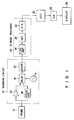
- Fig. 1 is a block diagram showing a schematic arrangement of the first embodiment.
- a scanning circuit 12 is connected to an electronic sector scanning type ultrasonic probe 10.
- the probe 10 is constituted by a large number of ultrasonic transducers arranged in a line.
- the probe 10 can scan an object to be examined with an ultrasonic beam of which radiation direction is changed in the form of a sector or can focus the ultrasonic beam by changing the application timing of a voltage applied to each transducer.
- the probe 10 is not limited to an electronic sector scanning type but may be a linear scanning type or mechanical scanning type probe.
- an output from an oscillator 14 for determining a frequency at which each ultrasonic transducer is vibrated is supplied to the probe 10 through a delay circuit 16 and a pulse generator 18.
- the pulse generator 18 supplies driving pulses (rate pulses) to the probe 10 at a predetermined period. The reciprocal of this period is the repeating frequency of an ultrasonic beam.
- the delay circuit 16 is constituted by a large number of delay lines having different delay times. Outputs from the delay lines are respectively supplied to the large number of transducers. By changing these delay times, the direction (raster direction) of an ultrasonic beam radiated from the probe 10 can be changed.
- the delay times i.e., the radiation directions of ultrasonic waves, are controlled by control signals from a control section (not shown).
- An output signal from the probe 10 is supplied to an adder 22 through a preamplifier 20 and the delay circuit 16.
- an output from each transducer is supplied to the adder 22 through a corresponding one of the delay lines with the same delay time as that in a transmission period.
- An output from the adder 22 is input to a B-mode processing circuit 24, and the intensity of a reflected wave of the ultrasonic beam in each raster direction is detected.
- the B-mode processing circuit 24 is constituted by a logarithmic amplifier 26, an envelope detector 28 and an A/D converter 30.
- the logarithmic amplifier 26 logarithmically amplifies the reflected wave signal output from the adder 22.
- the envelope detector 28 detects the envelope of a signal from the logarithmic amplifier 26.
- An output from the B-mode processing circuit 24 is input, as luminance information of each raster, i.e., B-mode image (tomographic image) information, to a digital scan converter (DSC) 32.
- DSC digital scan converter
- the DSC 32 Since the raster of the ultrasonic wave from the ultrasonic probe 10 has a sector shape, and the raster of a display section 36 is formed in the lateral direction like the raster in the normal television signal, the DSC 32 outputs the image information upon changing the raster direction (scan direction) of the input image.
- the monochromatic tomographic image output from the DSC 32 is supplied to the display section 36 through a D/A converter 34.
- a D/A converter 34 may be supplied to a recording section such as a VCR.
- the DSC 32 in this embodiment not only serves to change the scan direction but also serves as a noise reducer for removing random noises by utilizing frame correlation.
- Fig. 2 is a block diagram showing the DSC 32 in detail.
- An image signal of each raster from the A/D converter 30 is input to one-input/three-output multiplexer 40.
- the multiplexer 40 sequentially outputs the input image signals of the respective rasters to the first, second and third output terminals repeatedly in this order.
- Buffer memories 42a, 42b and 42c each of which is capable of storing one-line (one-raster) image data, are respectively connected to the first, second and third output terminals of the multiplexer 40.
- one of the buffer memories 42a, 42b and 42c is sequentially selected and set in a write mode by the multiplexer 40.
- the output terminals of the buffer memories 42a, 42b and 42c are connected to a three-input/two-output multiplexer 44.
- the multiplexer 44 is electrically interlocked with the multiplexer 40 in such a manner that the multiplexer 44 selects buffer memories which are not selected by the multiplexer 40, i.e., two buffer memories in which no data are currently being written, and outputs image data of two rasters prior to the raster of the currently written data.
- Two output signals A and B from the multiplexer 44 are input to an interpolation circuit 46 and a raster correlation detector 48.
- the interpolation circuit 46 obtains image data of the pixel in the television signal between image data of two adjacent rasters by interpolating these data.
- An interpolation coefficient ⁇ varies depending on the position of data to be interpolated and is supplied from a controller 60 for generating an address signal for a frame memory 56.
- the raster correlation detector 48 detects the degree of correlation ⁇ between the two rasters from the image data of the two rasters.
- An output x n from the interpolation circuit 46 is supplied to the first input terminal (+) of an adder 50.
- Data y n-1 of the previous frame prior to the current frame by one is read out from the frame memory 56 and supplied to the second input terminal (-) of the adder 50.
- the motion detector/frame correlation calculator 52 performs frame correlation processing by using a frame correlation coefficient ⁇ determined in accordance with the raster correlation degree ⁇ and the output ⁇ from the adder 50.
- An output ⁇ ⁇ ⁇ from the motion detector/frame correlation calculator 52 is supplied to the first input terminal (+) of an adder 54.
- the data y n-1 from the frame memory 56 is supplied to the second input terminal (-) of the adder 54.
- the frame memory 56 stores tomographic data input in units of raster directions of the ultrasonic beams, and outputs the respective pixel data of the tomographic image in accordance with the scanning sequence of the display section 36.
- the scanning circuit 12 causes the ultrasonic probe 10 to scan the object with an ultrasonic wave of which the radiation direction is changed in the form of a sector, and reflected wave signals are envelope-detected by the B-mode processing circuit 24, thereby inputting image data of each sector raster to the DSC 32.
- the DSC 32 generates image data arranged in a matrix form from the image data arranged in the form of a sector raster, and writes the generated image data in the frame memory 56.
- Image data which does not exist on the raster of the ultrasonic beam is obtained by the interpolation circuit 46 in the following manner.
- the motion detector/frame correlation calculator 52 obtains the product of the difference ⁇ and the frame correlation coefficient ⁇ .
- the adder 54 then adds the product ⁇ ⁇ ⁇ and the image data y n-1 of a previous frame together to obtain the pixel data y n of the current frame, as seen from equation (2).
- the frame correlation parameter ⁇ is constant, an operation is performed in the same manner as in the conventional frame correlation without performing motion detection. If the frame correlation parameter ⁇ is changed in two values in accordance with whether or not the image is a motion image, an operation is performed in the same manner as in the conventional motion adaptive frame correlation scheme. In the present invention, however, a slight change of the path of an ultrasonic wave due to a slight motion of the patient, caused by respiration or heartbeat and which causes only the speckle pattern, and a change in the signal component of the image are separately detected. The frame correlation coefficient ⁇ is changed in accordance with the result of detection. Therefore, proper frame correlation processing can always be performed to obtain a tomographic image with a high S/N ratio.
- the raster correlation detector 48 receives the image data A and B and outputs a parameter ⁇ representing the following raster correlation: If [A - B
- ⁇ th1, then ⁇ 3. If th1 ⁇
- ⁇ th2, then ⁇ 2. If th2 ⁇
- ⁇ th3, then ⁇ 1. If th3 ⁇
- , then ⁇ 0. where th1, th2 and th3 are constants, and th1 ⁇ th2 ⁇ th3. Thus, the value of the parameter ⁇ is decreased as the degree of raster correlation is increased.
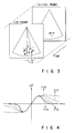
- the motion detector/frame correlation calculator 52 performs a nonlinear arithmetic operation for calculating ⁇ ⁇ ⁇ in accordance with the value ⁇ as shown in Fig. 4.
- the absolute value of ⁇ is small
- the absolute value of ⁇ ⁇ ⁇ is small.
- the absolute value of ⁇ is increased
- the absolute value of ⁇ ⁇ ⁇ is also increased.
- the absolute value of ⁇ exceeds a predetermined value
- the absolute value of ⁇ ⁇ ⁇ is decreased.
- the nonlinear arithmetic operation of the motion detector/frame correlation calculator 52 is classified into four patterns in accordance with the parameter ⁇ as shown in Fig. 4.
- Table 1 shows changes in the difference ⁇ between frames and changes in raster correlation parameter ⁇ for each of the signal component, random noise component and speckle pattern component in accordance with the types of image (the types of motion of the probe in the case of the ultrasonic diagnosing apparatus).
- Table 2 shows the tendency of the frame correlation coefficient ⁇ with respect to the values ⁇ and ⁇ and corresponds to Fig. 4.
- Table 1 Compoment Still Image Slight Motion Motion Image ⁇ ⁇ ⁇ ⁇ ⁇ ⁇ Signal 0 Large Small Large Large Random Noise Large Small Large Small Large Small Speckle Pattern 0 Large Large Middle Large Middle
- the type of image (a motion image, an image with a slight motion, or a still image) is detected on the basis of the difference ⁇ between the frames of image signals, and the raster correlation ⁇ within the current frame, and the frame correlation coefficient ⁇ is changed in accordance with the detection result, as shown in Fig. 4 and Table 2, thus performing proper frame correlation processing. Therefore, when a doctor or an operator moves the probe high speed to quickly observe the entire body of a patient ( ⁇ of the signal component is large), the frame correlation coefficient ⁇ is reduced as shown in Fig. 4, and blurring between frames is suppressed, thus obtaining an excellent realtime image.
- an ultrasonic diagnosing apparatus which can always perform proper frame correlation processing by separately detecting a slight motion only causing a speckle pattern and a motion image in which the signal component is changed, and changing the frame correlation coefficient in accordance with the detection result, and can obtain a tomographic image with a high S/N ratio.
- a motion of the image is detected by using three items of data, i.e., interpolated data of the current frame and data on two rasters on both sides of the interpolated data, and one item of data of the corresponding pixel in the previous frame.
- a plurality of frame memories may be used to use data at the same pixel among a plurality of frames, e.g., a frame prior to the current frame by one, a frame prior to the current frame by two, ... and/or data of adjacent pixels.
- a recursive digital filter of first order is used for processing the interpolated pixel data of the current frame and the pixel data of the previous frame prior to the current frame by one in a frame correlation processing.
- a recursive digital filter of any order except first may be formed by using a plurality of frame memories, as shown in Fig. 5. In Fig. 5,
- the interpolation circuit 46, the raster correlation detector 48, and the motion detector/frame correlation calculator 52 may be constituted by a ROM.
Landscapes
- Engineering & Computer Science (AREA)
- Computer Networks & Wireless Communication (AREA)
- Physics & Mathematics (AREA)
- General Physics & Mathematics (AREA)
- Radar, Positioning & Navigation (AREA)
- Remote Sensing (AREA)
- Ultra Sonic Daignosis Equipment (AREA)
- Investigating Or Analyzing Materials By The Use Of Ultrasonic Waves (AREA)
- Image Processing (AREA)
- Closed-Circuit Television Systems (AREA)
- Image Analysis (AREA)
Claims (5)
- Ultraschall-Diagnosegerät für die Abtastung eines zu untersuchenden Objekts mit Hilfe einer Ultraschallwelle und für die Bildung eines tomographischen Bilds des Objekts auf der Basis von reflektierten Ultraschallwellen, mit:
einer Rahmen- bzw. Bild-Korrelationsverarbeitungseinrichtung (54) für die Durchführung einer Rahmen- bzw. Bild-Korrelationsverarbeitung unter Heranziehung eines früheren tomographischen Bilds Yn-1, von aktuellen tomographischen Bilddaten xn und eines Rahmen- bzw. Bild-Korrelationskoeffizienten β, wobei die Rahmen- bzw. Bild-Korrelationsverarbeitung zur Bildung eines aktuellen tomographischen Bilds yn dient und der Rahmen- bzw. Bild-Korrelationskoeffizient β auf der Grundlage einer Bewegung des Bilds bestimmt wird,
dadurch gekennzeichnet, daß es aufweist:
eine Einrichtung (48, 52) für die Erfassung einer Art der Bewegung eines Bilds in Abhängigkeit von (i) einem Zwischenbildunterschied ε bei den Bilddaten zwischen den aktuellen tomographischen Bilddaten xn und dem früheren tomographischen Bild, und von (ii) einer Rasterkorrelation γ zwischen zwei benachbarten Abtastzeilen der Ultraschallwelle in den aktuellen tomographischen Bilddaten; und
eine Einrichtung (48, 52) für die Änderung des Rahmen- bzw. Bild-Korrelationskoeffizienten, der bei der Rahmen- bzw. Bild-Korrelationsverarbeitung eingesetzt wird, in Abhängigkeit von der durch die Erfassungseinrichtung erfaßten Art der Bewegung des Bilds. - Gerät nach Anspruch 1, dadurch gekennzeichnet, daß die Rahmen- bzw. Bild-Korrelationsverarbeitungseinrichtung (54) eine Einrichtung zum Multiplizieren (i) des Zwischenbildunterschieds ε und des Rahmen- bzw. Bild-Korrelationskoeffizienten β und zum Addieren des Ergebnisses der Multiplikation zu dem früheren tomographischen Bild für die Erzeugung eines aktuellen tomographischen Bilds aufweist.
- Gerät nach Anspruch 1 oder 2, dadurch gekennzeichnet, daß es aufweist:
eine Abtasteinrichtung (12) für die Abtastung eines zu untersuchenden Objekts mit einer Ultraschallwelle, deren Strahlungsrichtung mit einer sektorförmigen Gestalt geändert wird; und
eine Einrichtung (28) für die Erfassung von Bildelementdaten aus einem empfangenen Signal, das von der Abtasteinrichtung (12) abgegeben wird, wobei die Erfassungseinrichtung eine Einrichtung (46) für die Interpolation der Bildelementdaten aus empfangenen Signalen für zwei benachbarte Abtastzeilen enthält. - Gerät nach Anspruch 3, dadurch gekennzeichnet, daß die Abtasteinrichtung (12) drei Pufferspeicher (n, n-1, n-2) für die Speicherung von reflektierten Ultraschallwellen von drei aufeinanderfolgenden Abtastzeilen aufweist, wobei einer der Pufferspeicher in eine Schreibbetriebsart versetzt ist und die beiden anderen Pufferspeicher in eine Lesebetriebsart versetzt sind und ausgelesene Daten an die Interpolationseinrichtung (46) und die Einrichtung (48, 52) zur Erfassung der Bewegungsart abgeben.
- Gerät nach einem der Ansprüche 1 bis 4, dadurch gekennzeichnet, daß die Einrichtung zum Ändern des Rahmen- bzw. Bild-Korrelationskoeffizienten einen kleinen Rahmen- bzw. Bild-Korrelationskoeffizienten berechnet, wenn der Zwischenbildunterschied groß ist und die Rasterkorrelation schwach ist, einen mittleren Rahmen- bzw. Bild-Korrelationskoeffizienten berechnet, wenn der Zwischenbildunterschied groß ist und die Rasterkorrelation stark ist, und einen großen Rahmen- bzw. Bild-Korrelationskoeffizienten berechnet, wenn der Zwischenbildunterschied llein ist und die Rasterkorrelation schwach ist.
Applications Claiming Priority (2)
| Application Number | Priority Date | Filing Date | Title |
|---|---|---|---|
| JP62036/91 | 1991-03-26 | ||
| JP3062036A JP2950632B2 (ja) | 1991-03-26 | 1991-03-26 | 超音波診断装置 |
Publications (2)
| Publication Number | Publication Date |
|---|---|
| EP0505948A1 EP0505948A1 (de) | 1992-09-30 |
| EP0505948B1 true EP0505948B1 (de) | 1995-12-20 |
Family
ID=13188540
Family Applications (1)
| Application Number | Title | Priority Date | Filing Date |
|---|---|---|---|
| EP92104917A Expired - Lifetime EP0505948B1 (de) | 1991-03-26 | 1992-03-20 | Ultraschall-Diagnose-Gerät |
Country Status (4)
| Country | Link |
|---|---|
| US (1) | US5734738A (de) |
| EP (1) | EP0505948B1 (de) |
| JP (1) | JP2950632B2 (de) |
| DE (1) | DE69206860T2 (de) |
Families Citing this family (12)
| Publication number | Priority date | Publication date | Assignee | Title |
|---|---|---|---|---|
| US5774870A (en) * | 1995-12-14 | 1998-06-30 | Netcentives, Inc. | Fully integrated, on-line interactive frequency and award redemption program |
| US5873830A (en) * | 1997-08-22 | 1999-02-23 | Acuson Corporation | Ultrasound imaging system and method for improving resolution and operation |
| JP4061721B2 (ja) * | 1998-07-16 | 2008-03-19 | 松下電器産業株式会社 | 映像信号処理回路および映像信号処理方法 |
| US6162174A (en) * | 1998-09-16 | 2000-12-19 | Siemens Medical Systems, Inc. | Method for compensating for object movement in ultrasound images |
| US6117081A (en) * | 1998-10-01 | 2000-09-12 | Atl Ultrasound, Inc. | Method for correcting blurring of spatially compounded ultrasonic diagnostic images |
| US6775400B1 (en) * | 1999-10-29 | 2004-08-10 | Acuson Corporation | Medical diagnostic ultrasonic imaging method and apparatus for suppressing electronic noise |
| US6464638B1 (en) | 2000-10-05 | 2002-10-15 | Koninklijke Philips Electronics N.V. | Ultrasound imaging system and method for spatial compounding |
| JP5171610B2 (ja) * | 2006-02-22 | 2013-03-27 | 株式会社日立メディコ | 超音波診断装置 |
| JP5186088B2 (ja) * | 2006-05-23 | 2013-04-17 | Hoya株式会社 | 内視鏡装置 |
| US7907217B2 (en) * | 2006-10-31 | 2011-03-15 | Siemens Medical Solutions Usa, Inc. | Systems and methods of subtraction angiography utilizing motion prediction |
| WO2009062062A1 (en) * | 2007-11-09 | 2009-05-14 | Imacor, Llc | Superimposed display of image contours |
| CN112734665B (zh) * | 2020-12-31 | 2023-07-14 | 飞依诺科技股份有限公司 | 用于减弱运动模糊的超声图像时域滤波方法、设备及介质 |
Family Cites Families (10)
| Publication number | Priority date | Publication date | Assignee | Title |
|---|---|---|---|---|
| JPS5578947A (en) * | 1978-12-08 | 1980-06-14 | Matsushita Electric Industrial Co Ltd | Method of displaying ultrasoniccwave diagnosis device |
| FR2589022B1 (fr) * | 1985-10-18 | 1988-05-27 | Thomson Csf | Procede et dispositif de generation d'images a partir de signaux ultra-sonores obtenus par echographie |
| FR2593698A1 (fr) * | 1986-01-31 | 1987-08-07 | Labo Electronique Physique | Appareil d'examen de milieux en mouvement par echographie ultrasonore |
| US4785818A (en) * | 1986-06-30 | 1988-11-22 | General Electric Company | Method and means or dynamically weighted temporal averaging of pixel data |
| US5111823A (en) * | 1989-04-20 | 1992-05-12 | National Fertility Institute | Apparatus and method for generating echographic images |
| US5224175A (en) * | 1987-12-07 | 1993-06-29 | Gdp Technologies, Inc. | Method for analyzing a body tissue ultrasound image |
| US5060515A (en) * | 1989-03-01 | 1991-10-29 | Kabushiki Kaisha Toshiba | Image signal processing circuit for ultrasonic imaging apparatus |
| FR2644913A1 (fr) * | 1989-03-24 | 1990-09-28 | Labo Electronique Physique | Dispositif d'imagerie par echographie ultrasonore, utilisant un filtre adaptatif perfectionne |
| GB8914843D0 (en) * | 1989-06-28 | 1989-08-16 | British Aerospace | A method of processing video image data for use in the storage or transmission of moving digital images |
| US5241473A (en) * | 1990-10-12 | 1993-08-31 | Ken Ishihara | Ultrasonic diagnostic apparatus for displaying motion of moving portion by superposing a plurality of differential images |
-
1991
- 1991-03-26 JP JP3062036A patent/JP2950632B2/ja not_active Expired - Lifetime
-
1992
- 1992-03-20 EP EP92104917A patent/EP0505948B1/de not_active Expired - Lifetime
- 1992-03-20 DE DE69206860T patent/DE69206860T2/de not_active Expired - Fee Related
-
1994
- 1994-08-09 US US08/288,223 patent/US5734738A/en not_active Expired - Lifetime
Also Published As
| Publication number | Publication date |
|---|---|
| JP2950632B2 (ja) | 1999-09-20 |
| EP0505948A1 (de) | 1992-09-30 |
| US5734738A (en) | 1998-03-31 |
| DE69206860T2 (de) | 1996-09-05 |
| JPH04297246A (ja) | 1992-10-21 |
| DE69206860D1 (de) | 1996-02-01 |
Similar Documents
| Publication | Publication Date | Title |
|---|---|---|
| US4887306A (en) | Adaptive temporal filter for ultrasound imaging system | |
| US6056693A (en) | Ultrasound imaging with synthetic transmit focusing | |
| US4751846A (en) | Reducing noise in ultrasonic images | |
| US5060515A (en) | Image signal processing circuit for ultrasonic imaging apparatus | |
| US5873830A (en) | Ultrasound imaging system and method for improving resolution and operation | |
| US4785818A (en) | Method and means or dynamically weighted temporal averaging of pixel data | |
| EP0505948B1 (de) | Ultraschall-Diagnose-Gerät | |
| US5940123A (en) | High resolution ultrasonic imaging through interpolation of received scanline data | |
| US4771470A (en) | Noise reduction method and apparatus for medical ultrasound | |
| US4750367A (en) | Device for examining moving objects by means of ultrasound echography | |
| US6790181B2 (en) | Overlapped scanning for multi-directional compounding of ultrasound images | |
| US4386528A (en) | Method and means for generating pixel data in an ultrasonic scanning system | |
| US4375671A (en) | Method and means for filtering and updating pixel data | |
| JPH0663046A (ja) | 走査された超音波画像の適応的なコントラスト強化方法 | |
| JPH0352034B2 (de) | ||
| US5776066A (en) | Method and apparatus for creating adaptively focused ultrasound images | |
| US5865752A (en) | Method and apparatus for ultrasound imaging using normalized difference between successive frames | |
| US4386529A (en) | Method and means for improving video display image | |
| US5718230A (en) | Method and apparatus for creating ultrasound images using a reduced number of transmit beam lines | |
| US4448201A (en) | Digital scan converter | |
| US5083566A (en) | Ultrasonic imaging apparatus | |
| JP4137202B2 (ja) | 超音波診断装置 | |
| JPS6391783A (ja) | 画像信号のスム−ジング処理方法 | |
| JPH02228950A (ja) | 超音波診断装置の画像信号処理回路 | |
| JPH05277101A (ja) | 超音波診断装置 |
Legal Events
| Date | Code | Title | Description |
|---|---|---|---|
| PUAI | Public reference made under article 153(3) epc to a published international application that has entered the european phase |
Free format text: ORIGINAL CODE: 0009012 |
|
| 17P | Request for examination filed |
Effective date: 19920320 |
|
| AK | Designated contracting states |
Kind code of ref document: A1 Designated state(s): DE FR NL |
|
| 17Q | First examination report despatched |
Effective date: 19940630 |
|
| GRAA | (expected) grant |
Free format text: ORIGINAL CODE: 0009210 |
|
| AK | Designated contracting states |
Kind code of ref document: B1 Designated state(s): DE FR NL |
|
| REF | Corresponds to: |
Ref document number: 69206860 Country of ref document: DE Date of ref document: 19960201 |
|
| ET | Fr: translation filed | ||
| PLBE | No opposition filed within time limit |
Free format text: ORIGINAL CODE: 0009261 |
|
| STAA | Information on the status of an ep patent application or granted ep patent |
Free format text: STATUS: NO OPPOSITION FILED WITHIN TIME LIMIT |
|
| 26N | No opposition filed | ||
| PGFP | Annual fee paid to national office [announced via postgrant information from national office to epo] |
Ref country code: NL Payment date: 20080303 Year of fee payment: 17 |
|
| PGFP | Annual fee paid to national office [announced via postgrant information from national office to epo] |
Ref country code: FR Payment date: 20080311 Year of fee payment: 17 Ref country code: DE Payment date: 20080313 Year of fee payment: 17 |
|
| NLV4 | Nl: lapsed or anulled due to non-payment of the annual fee |
Effective date: 20091001 |
|
| REG | Reference to a national code |
Ref country code: FR Ref legal event code: ST Effective date: 20091130 |
|
| PG25 | Lapsed in a contracting state [announced via postgrant information from national office to epo] |
Ref country code: DE Free format text: LAPSE BECAUSE OF NON-PAYMENT OF DUE FEES Effective date: 20091001 |
|
| PG25 | Lapsed in a contracting state [announced via postgrant information from national office to epo] |
Ref country code: NL Free format text: LAPSE BECAUSE OF NON-PAYMENT OF DUE FEES Effective date: 20091001 |
|
| PG25 | Lapsed in a contracting state [announced via postgrant information from national office to epo] |
Ref country code: FR Free format text: LAPSE BECAUSE OF NON-PAYMENT OF DUE FEES Effective date: 20091123 |