EP0505945A1 - Device for removal of gas-liquid mixtures from electrolysis cells - Google Patents
Device for removal of gas-liquid mixtures from electrolysis cells Download PDFInfo
- Publication number
- EP0505945A1 EP0505945A1 EP92104913A EP92104913A EP0505945A1 EP 0505945 A1 EP0505945 A1 EP 0505945A1 EP 92104913 A EP92104913 A EP 92104913A EP 92104913 A EP92104913 A EP 92104913A EP 0505945 A1 EP0505945 A1 EP 0505945A1
- Authority
- EP
- European Patent Office
- Prior art keywords
- gas
- duct
- removal
- rich phase
- liquid
- Prior art date
- Legal status (The legal status is an assumption and is not a legal conclusion. Google has not performed a legal analysis and makes no representation as to the accuracy of the status listed.)
- Withdrawn
Links
- 239000007788 liquid Substances 0.000 title claims abstract description 41
- 238000005868 electrolysis reaction Methods 0.000 title claims abstract description 11
- 239000000203 mixture Substances 0.000 title abstract description 10
- 239000003792 electrolyte Substances 0.000 claims description 7
- 230000003247 decreasing effect Effects 0.000 claims 1
- 239000012528 membrane Substances 0.000 abstract description 20
- 238000000926 separation method Methods 0.000 abstract description 2
- 239000007789 gas Substances 0.000 description 33
- 239000012071 phase Substances 0.000 description 21
- 239000007791 liquid phase Substances 0.000 description 15
- HEMHJVSKTPXQMS-UHFFFAOYSA-M Sodium hydroxide Chemical compound [OH-].[Na+] HEMHJVSKTPXQMS-UHFFFAOYSA-M 0.000 description 6
- 239000003014 ion exchange membrane Substances 0.000 description 6
- XLYOFNOQVPJJNP-UHFFFAOYSA-N water Substances O XLYOFNOQVPJJNP-UHFFFAOYSA-N 0.000 description 6
- FAPWRFPIFSIZLT-UHFFFAOYSA-M Sodium chloride Chemical compound [Na+].[Cl-] FAPWRFPIFSIZLT-UHFFFAOYSA-M 0.000 description 4
- 239000003513 alkali Substances 0.000 description 4
- 239000000243 solution Substances 0.000 description 4
- 229920000557 Nafion® Polymers 0.000 description 3
- 238000005299 abrasion Methods 0.000 description 3
- 239000007792 gaseous phase Substances 0.000 description 3
- 238000003780 insertion Methods 0.000 description 3
- 230000037431 insertion Effects 0.000 description 3
- ZAMOUSCENKQFHK-UHFFFAOYSA-N Chlorine atom Chemical compound [Cl] ZAMOUSCENKQFHK-UHFFFAOYSA-N 0.000 description 2
- 239000000460 chlorine Substances 0.000 description 2
- 229910052801 chlorine Inorganic materials 0.000 description 2
- 239000011552 falling film Substances 0.000 description 2
- 239000012530 fluid Substances 0.000 description 2
- 238000005259 measurement Methods 0.000 description 2
- 239000011780 sodium chloride Substances 0.000 description 2
- 230000006641 stabilisation Effects 0.000 description 2
- 238000011105 stabilization Methods 0.000 description 2
- KZBUYRJDOAKODT-UHFFFAOYSA-N Chlorine Chemical compound ClCl KZBUYRJDOAKODT-UHFFFAOYSA-N 0.000 description 1
- 229920003935 Flemion® Polymers 0.000 description 1
- UFHFLCQGNIYNRP-UHFFFAOYSA-N Hydrogen Chemical compound [H][H] UFHFLCQGNIYNRP-UHFFFAOYSA-N 0.000 description 1
- 230000002547 anomalous effect Effects 0.000 description 1
- QVGXLLKOCUKJST-UHFFFAOYSA-N atomic oxygen Chemical compound [O] QVGXLLKOCUKJST-UHFFFAOYSA-N 0.000 description 1
- 238000005452 bending Methods 0.000 description 1
- 230000005540 biological transmission Effects 0.000 description 1
- 230000015572 biosynthetic process Effects 0.000 description 1
- 239000012267 brine Substances 0.000 description 1
- 239000011248 coating agent Substances 0.000 description 1
- 238000000576 coating method Methods 0.000 description 1
- 230000001276 controlling effect Effects 0.000 description 1
- 238000009792 diffusion process Methods 0.000 description 1
- 238000001035 drying Methods 0.000 description 1
- 230000000694 effects Effects 0.000 description 1
- 238000005516 engineering process Methods 0.000 description 1
- 239000004744 fabric Substances 0.000 description 1
- 239000001257 hydrogen Substances 0.000 description 1
- 229910052739 hydrogen Inorganic materials 0.000 description 1
- 238000009434 installation Methods 0.000 description 1
- 238000005342 ion exchange Methods 0.000 description 1
- 238000004519 manufacturing process Methods 0.000 description 1
- 239000001301 oxygen Substances 0.000 description 1
- 229910052760 oxygen Inorganic materials 0.000 description 1
- 230000002035 prolonged effect Effects 0.000 description 1
- 230000001105 regulatory effect Effects 0.000 description 1
- 230000002787 reinforcement Effects 0.000 description 1
- 238000007789 sealing Methods 0.000 description 1
- HPALAKNZSZLMCH-UHFFFAOYSA-M sodium;chloride;hydrate Chemical compound O.[Na+].[Cl-] HPALAKNZSZLMCH-UHFFFAOYSA-M 0.000 description 1
- 239000007921 spray Substances 0.000 description 1
- 239000000126 substance Substances 0.000 description 1
- 238000009736 wetting Methods 0.000 description 1
Images


Classifications
-
- C—CHEMISTRY; METALLURGY
- C25—ELECTROLYTIC OR ELECTROPHORETIC PROCESSES; APPARATUS THEREFOR
- C25B—ELECTROLYTIC OR ELECTROPHORETIC PROCESSES FOR THE PRODUCTION OF COMPOUNDS OR NON-METALS; APPARATUS THEREFOR
- C25B15/00—Operating or servicing cells
- C25B15/08—Supplying or removing reactants or electrolytes; Regeneration of electrolytes
-
- C—CHEMISTRY; METALLURGY
- C25—ELECTROLYTIC OR ELECTROPHORETIC PROCESSES; APPARATUS THEREFOR
- C25B—ELECTROLYTIC OR ELECTROPHORETIC PROCESSES FOR THE PRODUCTION OF COMPOUNDS OR NON-METALS; APPARATUS THEREFOR
- C25B15/00—Operating or servicing cells
- C25B15/02—Process control or regulation
- C25B15/023—Measuring, analysing or testing during electrolytic production
-
- C—CHEMISTRY; METALLURGY
- C25—ELECTROLYTIC OR ELECTROPHORETIC PROCESSES; APPARATUS THEREFOR
- C25B—ELECTROLYTIC OR ELECTROPHORETIC PROCESSES FOR THE PRODUCTION OF COMPOUNDS OR NON-METALS; APPARATUS THEREFOR
- C25B9/00—Cells or assemblies of cells; Constructional parts of cells; Assemblies of constructional parts, e.g. electrode-diaphragm assemblies; Process-related cell features
- C25B9/07—Common duct cells
-
- C—CHEMISTRY; METALLURGY
- C25—ELECTROLYTIC OR ELECTROPHORETIC PROCESSES; APPARATUS THEREFOR
- C25B—ELECTROLYTIC OR ELECTROPHORETIC PROCESSES FOR THE PRODUCTION OF COMPOUNDS OR NON-METALS; APPARATUS THEREFOR
- C25B9/00—Cells or assemblies of cells; Constructional parts of cells; Assemblies of constructional parts, e.g. electrode-diaphragm assemblies; Process-related cell features
- C25B9/70—Assemblies comprising two or more cells
- C25B9/73—Assemblies comprising two or more cells of the filter-press type
Definitions
- ion-exchange polymeric membranes such as Nafion (R) /Du Pont de Nemours, Flemion (R) /Asahi Glass and others.
- ion-exchange membranes are produced in the form of sheets, even of considerable dimensions, with a thickness that ranges from 0.2 to 0.5 mm max.
- a reinforcement fabric membranes are still affected by a low mechanical resistance, especially to abrasion and bending.
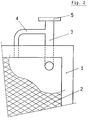
- Fig. 1 shows a cell of a membrane electrolyzer equipped with a frame (1) to ensure, together with suitable gaskets, a waterproof sealing along the edges of the several cells assembled to form the electrolyzer in the so-called "filter-press configuration".
- the cell comprises also an electrode (2) consisting in a foraminous sheet, such as expanded or perforated sheet or a screen provided, if necessary, with an appropriate electrocatalytic coating; an inlet (6) and an outlet duct (3); flanges (7, 5) for connection to feeding and removal loops, as known in the art.
- the cell is also supplied, according to the present invention, with a duct (4) for the removal of gas-rich products, one end of which is connected to the top of the cell and the other to the middle portion of outlet duct (3) for the removal of the liquid-rich phase.
- the stabilization of the liquid level between line (10) and the edge of the flange (1) requires an appropriate balancing of the section and the length of the ducts (3, 4), in the area comprised between the outlet from the cell and the point wherein the two pipes meet, with the aim of maintaining said pressure in top of the cell below the pressure drop which occurs inside the duct for the liquid-rich phase removal; on the other hand the minimum value of said pressure in the top of the cell should never decrease below the value of the total pressure drop inside the duct for the liquid-rich phase removal subtracted by the height of liquid defined by line (10) and the edge (1) of the flange.
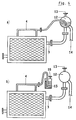
- Fig. 5 and 6 show further embodiments of the present invention, wherein the elements are equipped with an outlet duct for the liquid-rich phase situated in a horizontal position.
- the duct for the gas-rich phase (4) is connected to the liquid-rich phase duct (3) at a distance from the cell outlet significantly greater than the usual distance in cells with a vertical outlet (Fig. 1, 2, 3, 4).
- the insertion of the gaseous phase duct (4) into the liquid phase duct (3) is made in a position which is not at all critical with the only requirement that the cross section and length of ducts (3, 4) between the outlet from the cell and the conjunction of the two ducts meet the above discussed condition necessary for stabilization of the liquid level inside the cell.
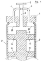
- Fig. 7 schematizes a further embodiment of the invention, wherein the two ducts ((3) and (4)) for separately removing the liquid and the gas phases are coaxial; this embodiment presents the advantage of eliminating the connection between the gas phase duct (4) and the flange (1), with a consequent reduction of production costs and an increase of the element mechanical reliability.
- An experimental electrolyzer of monopolar type was assembled using 6 anodic elements, 5 cathodic elements, 2 terminal cathodic elements of the type schematized in Fig. 1, each of them being 1200 mm high and 1500 mm wide, with a resulting area of 1.8 m2; the anodic elements were connected through the ducts (3) to an anodic gas-disengager, the cathodic elements were similarly connected to a cathodic gas-disengager.
- the top of each element was provided with two connections (3, 4) for separately removing the gas-rich and the liquid-rich phases as described in the present invention.
Landscapes
- Chemical & Material Sciences (AREA)
- Engineering & Computer Science (AREA)
- Chemical Kinetics & Catalysis (AREA)
- Electrochemistry (AREA)
- Materials Engineering (AREA)
- Metallurgy (AREA)
- Organic Chemistry (AREA)
- Analytical Chemistry (AREA)
- Automation & Control Theory (AREA)
- Electrolytic Production Of Non-Metals, Compounds, Apparatuses Therefor (AREA)
- Degasification And Air Bubble Elimination (AREA)
Applications Claiming Priority (2)
| Application Number | Priority Date | Filing Date | Title |
|---|---|---|---|
| ITMI910766 | 1991-03-21 | ||
| ITMI910766A IT1247483B (it) | 1991-03-21 | 1991-03-21 | Dispositivo per l'estrazione di fluidi bifase da celle di elettrolisi |
Publications (1)
| Publication Number | Publication Date |
|---|---|
| EP0505945A1 true EP0505945A1 (en) | 1992-09-30 |
Family
ID=11359172
Family Applications (1)
| Application Number | Title | Priority Date | Filing Date |
|---|---|---|---|
| EP92104913A Withdrawn EP0505945A1 (en) | 1991-03-21 | 1992-03-20 | Device for removal of gas-liquid mixtures from electrolysis cells |
Country Status (17)
| Country | Link |
|---|---|
| US (1) | US5242564A (cs) |
| EP (1) | EP0505945A1 (cs) |
| JP (1) | JPH06200392A (cs) |
| KR (1) | KR920018791A (cs) |
| CN (1) | CN1065104A (cs) |
| AR (1) | AR244813A1 (cs) |
| AU (1) | AU652426B2 (cs) |
| BR (1) | BR9200988A (cs) |
| CA (1) | CA2063192A1 (cs) |
| CS (1) | CS85792A3 (cs) |
| FI (1) | FI921155A7 (cs) |
| HU (1) | HUT62041A (cs) |
| IT (1) | IT1247483B (cs) |
| MX (1) | MX9201259A (cs) |
| NO (1) | NO921062L (cs) |
| PL (1) | PL167765B1 (cs) |
| ZA (1) | ZA922058B (cs) |
Cited By (5)
| Publication number | Priority date | Publication date | Assignee | Title |
|---|---|---|---|---|
| EP0599363A1 (en) * | 1992-11-23 | 1994-06-01 | Permascand Ab | Cell |
| EP0625591A3 (en) * | 1993-04-30 | 1995-01-11 | Chlorine Eng Corp Ltd | Electrolyzer. |
| WO2002038831A3 (en) * | 2000-11-13 | 2003-01-09 | Uhdenora Technologies Srl | Dual section system for the discharge of bi-phase gas-liquid mixtures |
| DE19526545B4 (de) * | 1994-07-20 | 2005-07-28 | Uhdenora Technologies S.R.L. | Elektrolyseur mit Ionenaustausch-Membran oder Diaphragma |
| EP2228466A1 (en) * | 2009-03-12 | 2010-09-15 | Honda Motor Co., Ltd. | Water electrolysis system |
Families Citing this family (4)
| Publication number | Priority date | Publication date | Assignee | Title |
|---|---|---|---|---|
| IT1263806B (it) * | 1993-01-22 | 1996-09-03 | Solvay | Elettrolizzatore per la produzione di un gas |
| JP2906986B2 (ja) * | 1994-03-25 | 1999-06-21 | 日本電気株式会社 | ウエット処理装置および電解活性水生成方法およびウエット処理方法 |
| JP6858841B2 (ja) * | 2017-03-31 | 2021-04-14 | 旭化成株式会社 | 外部ヘッダー型複極式エレメント、外部ヘッダー型複極式電解槽、及び水素製造方法 |
| CA3028546C (en) * | 2018-12-21 | 2024-06-18 | Empire Hydrogen Energy Systems Inc. | Water reservoir and electrolysis cell combination |
Citations (3)
| Publication number | Priority date | Publication date | Assignee | Title |
|---|---|---|---|---|
| US1535185A (en) * | 1920-01-26 | 1925-04-28 | John P Scott | Electrolytic apparatus |
| US3968021A (en) * | 1974-04-02 | 1976-07-06 | Ppg Industries, Inc. | Electrolytic cell having hydrogen gas disengaging apparatus |
| EP0435385A1 (fr) * | 1989-12-28 | 1991-07-03 | SOLVAY (Société Anonyme) | Electrolyseur pour la production d'un gaz, comprenant un empilage de cadres verticaux |
Family Cites Families (5)
| Publication number | Priority date | Publication date | Assignee | Title |
|---|---|---|---|---|
| US3945908A (en) * | 1974-06-20 | 1976-03-23 | Hooker Chemicals & Plastics Corporation | Liquid seal for chlorine headers |
| JPS599185A (ja) * | 1982-07-06 | 1984-01-18 | Asahi Chem Ind Co Ltd | イオン交換膜法電解槽 |
| US4632739A (en) * | 1985-07-19 | 1986-12-30 | Lavalley Industrial Plastics, Inc. | Electrolytic cell head with replaceable insert and method of protecting the same |
| US4705614A (en) * | 1986-05-12 | 1987-11-10 | The Dow Chemical Company | Cell with improved electrolyte flow distributor |
| US4839012A (en) * | 1988-01-05 | 1989-06-13 | The Dow Chemical Company | Antisurge outlet apparatus for use in electrolytic cells |
-
1991
- 1991-03-21 IT ITMI910766A patent/IT1247483B/it active IP Right Grant
-
1992
- 1992-03-12 US US07/850,413 patent/US5242564A/en not_active Expired - Fee Related
- 1992-03-17 CA CA002063192A patent/CA2063192A1/en not_active Abandoned
- 1992-03-17 AU AU12953/92A patent/AU652426B2/en not_active Ceased
- 1992-03-18 NO NO92921062A patent/NO921062L/no unknown
- 1992-03-18 HU HU9200905A patent/HUT62041A/hu unknown
- 1992-03-18 FI FI921155A patent/FI921155A7/fi not_active Application Discontinuation
- 1992-03-19 AR AR92321964A patent/AR244813A1/es active
- 1992-03-19 KR KR1019920004561A patent/KR920018791A/ko not_active Withdrawn
- 1992-03-20 ZA ZA922058A patent/ZA922058B/xx unknown
- 1992-03-20 EP EP92104913A patent/EP0505945A1/en not_active Withdrawn
- 1992-03-20 BR BR929200988A patent/BR9200988A/pt unknown
- 1992-03-20 MX MX9201259A patent/MX9201259A/es unknown
- 1992-03-20 CS CS92857A patent/CS85792A3/cs unknown
- 1992-03-20 PL PL92293922A patent/PL167765B1/pl unknown
- 1992-03-21 CN CN92101896A patent/CN1065104A/zh active Pending
- 1992-03-21 JP JP4064279A patent/JPH06200392A/ja active Pending
Patent Citations (3)
| Publication number | Priority date | Publication date | Assignee | Title |
|---|---|---|---|---|
| US1535185A (en) * | 1920-01-26 | 1925-04-28 | John P Scott | Electrolytic apparatus |
| US3968021A (en) * | 1974-04-02 | 1976-07-06 | Ppg Industries, Inc. | Electrolytic cell having hydrogen gas disengaging apparatus |
| EP0435385A1 (fr) * | 1989-12-28 | 1991-07-03 | SOLVAY (Société Anonyme) | Electrolyseur pour la production d'un gaz, comprenant un empilage de cadres verticaux |
Cited By (5)
| Publication number | Priority date | Publication date | Assignee | Title |
|---|---|---|---|---|
| EP0599363A1 (en) * | 1992-11-23 | 1994-06-01 | Permascand Ab | Cell |
| EP0625591A3 (en) * | 1993-04-30 | 1995-01-11 | Chlorine Eng Corp Ltd | Electrolyzer. |
| DE19526545B4 (de) * | 1994-07-20 | 2005-07-28 | Uhdenora Technologies S.R.L. | Elektrolyseur mit Ionenaustausch-Membran oder Diaphragma |
| WO2002038831A3 (en) * | 2000-11-13 | 2003-01-09 | Uhdenora Technologies Srl | Dual section system for the discharge of bi-phase gas-liquid mixtures |
| EP2228466A1 (en) * | 2009-03-12 | 2010-09-15 | Honda Motor Co., Ltd. | Water electrolysis system |
Also Published As
| Publication number | Publication date |
|---|---|
| NO921062L (no) | 1992-09-22 |
| MX9201259A (es) | 1992-10-30 |
| CN1065104A (zh) | 1992-10-07 |
| ITMI910766A1 (it) | 1992-09-21 |
| FI921155A0 (fi) | 1992-03-18 |
| PL167765B1 (pl) | 1995-10-31 |
| US5242564A (en) | 1993-09-07 |
| PL293922A1 (en) | 1992-11-30 |
| AU652426B2 (en) | 1994-08-25 |
| HUT62041A (en) | 1993-03-29 |
| AR244813A1 (es) | 1993-11-30 |
| ZA922058B (en) | 1992-11-25 |
| HU9200905D0 (en) | 1992-05-28 |
| CA2063192A1 (en) | 1992-09-22 |
| AU1295392A (en) | 1992-09-24 |
| KR920018791A (ko) | 1992-10-22 |
| CS85792A3 (en) | 1992-10-14 |
| FI921155A7 (fi) | 1992-09-22 |
| JPH06200392A (ja) | 1994-07-19 |
| ITMI910766A0 (it) | 1991-03-21 |
| IT1247483B (it) | 1994-12-17 |
| NO921062D0 (no) | 1992-03-18 |
| BR9200988A (pt) | 1992-11-24 |
Similar Documents
| Publication | Publication Date | Title |
|---|---|---|
| US4417960A (en) | Novel electrolyzer and process | |
| US4217199A (en) | Electrolytic cell | |
| US5225060A (en) | Bipolar, filter press type electrolytic cell | |
| EP0099693B1 (en) | Electrolytic cell with ion exchange membrane | |
| EP0383243A2 (en) | Electrolyser for chlor-alkali electrolysis, and anode | |
| US5242564A (en) | Device for removal of gas-liquid mixtures from electrolysis cells | |
| US4444631A (en) | Electrochemical purification of chlor-alkali cell liquor | |
| US5296121A (en) | Target electrode for preventing corrosion in electrochemical cells | |
| US4568433A (en) | Electrolytic process of an aqueous alkali metal halide solution | |
| US4069128A (en) | Electrolytic system comprising membrane member between electrodes | |
| US5593553A (en) | Electrolytic cell and electrode therefor | |
| US4222831A (en) | Internal gas separation assembly for high current density electrolytic cells | |
| EP1362133A1 (en) | Electrolysis cell with gas diffusion electrode operating at controlled pressure | |
| CA1314836C (en) | Process for the electrolysis of alkali metal chloride solutions | |
| US4556470A (en) | Electrolytic cell with membrane and solid, horizontal cathode plate | |
| US4248689A (en) | Electrolytic cell | |
| US4586994A (en) | Electrolytic process of an aqueous alkali metal halide solution and electrolytic cell used therefor | |
| US4344833A (en) | Restrictor apparatus for electrolyte flow conduit | |
| US4271004A (en) | Synthetic separator electrolytic cell | |
| JP3204322B2 (ja) | 塩化アルカリの電解方法 | |
| JP2001064793A (ja) | 複極式塩化アルカリ単位電解セル | |
| JPS6115159B2 (cs) | ||
| GB2038878A (en) | Apparatus and process for electrolysis of an aqueous alkali metal chloride solution |
Legal Events
| Date | Code | Title | Description |
|---|---|---|---|
| PUAI | Public reference made under article 153(3) epc to a published international application that has entered the european phase |
Free format text: ORIGINAL CODE: 0009012 |
|
| AK | Designated contracting states |
Kind code of ref document: A1 Designated state(s): AT BE CH DE DK ES FR GB GR IT LI LU MC NL PT SE |
|
| 17P | Request for examination filed |
Effective date: 19921103 |
|
| 17Q | First examination report despatched |
Effective date: 19940915 |
|
| GRAH | Despatch of communication of intention to grant a patent |
Free format text: ORIGINAL CODE: EPIDOS IGRA |
|
| STAA | Information on the status of an ep patent application or granted ep patent |
Free format text: STATUS: THE APPLICATION IS DEEMED TO BE WITHDRAWN |
|
| 18D | Application deemed to be withdrawn |
Effective date: 19960420 |