EP0505922A2 - Gerät und Verfahren zum Plotten mit Polygenzug-Vektorvorhersage - Google Patents
Gerät und Verfahren zum Plotten mit Polygenzug-Vektorvorhersage Download PDFInfo
- Publication number
- EP0505922A2 EP0505922A2 EP92104754A EP92104754A EP0505922A2 EP 0505922 A2 EP0505922 A2 EP 0505922A2 EP 92104754 A EP92104754 A EP 92104754A EP 92104754 A EP92104754 A EP 92104754A EP 0505922 A2 EP0505922 A2 EP 0505922A2
- Authority
- EP
- European Patent Office
- Prior art keywords
- velocity
- point
- pen
- maximum change
- major axis
- Prior art date
- Legal status (The legal status is an assumption and is not a legal conclusion. Google has not performed a legal analysis and makes no representation as to the accuracy of the status listed.)
- Withdrawn
Links
Images

Classifications
-
- G—PHYSICS
- G06—COMPUTING OR CALCULATING; COUNTING
- G06K—GRAPHICAL DATA READING; PRESENTATION OF DATA; RECORD CARRIERS; HANDLING RECORD CARRIERS
- G06K15/00—Arrangements for producing a permanent visual presentation of the output data, e.g. computer output printers
- G06K15/22—Arrangements for producing a permanent visual presentation of the output data, e.g. computer output printers using plotters
Definitions
- the present invention relates to graphic plotters and, more particularly, to a graphic plotter having a motor for driving a pen-holding carriage in the Y direction, a motor for driving a web of medium in the X direction and a motor controller for accelerating and driving the respective motors in such a manner that the pen draws a series of vector lines.
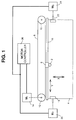
- FIG. 1 The major components of a conventional vector plotter are shown in simplified form in FIG. 1.
- the vectors are drawn on a sheet of paper 4 by a pen 2 which is mounted on a carriage 6 movable in the Y direction.
- the carriage 6 in turn is slidably mounted on a straight bar 16 and is also connected to a conveyor belt 8 which is rotatably supported by wheels 10 and 12.
- One of the two wheels -- in this example, wheel 12 -- is coupled to driving motor 14, which drives the belt 8, thereby causing displacement of pen 2 along the straight bar 16, i.e., along the Y axis.
- the paper sheet 4 is movable in the X direction by means of a pair of pinch rollers 18 and 22, which are driven by motors 20 and 24 respectively.
- Motors 14, 20 and 24 are controlled by motor controller 26 in accordance with the plotting data corresponding to the vectors to be drawn by the pen.
- U.S. Patent No. 4,776,097 discloses a technique for looking ahead at the characteristics of the next vector to be drawn and controlling the motors as a function of those characteristics to enable the most efficient drawing of that next vector.
- a step acceleration is applied to a motor if the next vector to be drawn has a length less than a predetermined value and a ramp acceleration is applied to the motor if the next vector to be drawn has a length greater than that predetermined value.
- U.S. Patent No. 4,062,648 discloses a plotter system wherein the velocity at which a next vector is to be drawn by a pen is selected in dependence on the length of that next vector to be drawn.
- the pen starts and ends each vector line segment at zero velocity, i.e., at the start and end of each vector the X and Y velocity components equal zero.
- the velocity is ramped up at the beginning of each segment, and ramped back down at the end.
- the velocity for the major axis (the longest axis) is ramped at the predetermined acceleration rate which the machine is capable of (i.e. 4g).
- the minor axis velocity will be the slope of the line (minor axis length divided by major axis length) times the major axis velocity.
- the acceleration experienced by the minor axis will be equal to the major axis acceleration for 45 degree lines, and less for all others.
- U.S. Patent No. 3,893,616 discloses an electromechanical plotter wherein the speed of the pen is controlled to produce nonzero velocity at the end points of line segments.
- this patent does not disclose how to determine the optimal pen velocity at any instant.
- Such a system is disadvantageous because any deviation from the optimal velocity results in inaccurate plotting.
- the velocity must be optimized in dependence on the electromechanical constraints of the plotter, the lengths of the line segments and the changes in direction of successive line segments.
- the foregoing object of the invention is achieved in accordance with the vector plotter of the invention by incorporating means for performing a vector lookahead technique that enables a polyline to be plotted without coming back to zero velocity between each line segment or vector. This requires ramping up the major axis velocity during each segment at the beginning of the curve, and ramping back down during each segment at the end of the curve.
- the velocity for the major axis (the longest axis) is ramped at the predetermined acceleration rate which the machine is capable of (i.e. 4g).
- the minor axis velocity will be the slope of the line (minor axis length divided by major axis length) times the major axis velocity.
- the minor axis will still see an acceleration which is the ratio of slope times the major axis acceleration. However, it will see an additional acceleration which is due to direction change. At each vertex, the slope will change and the minor axis will have an instantaneous acceleration due to direction change.
- minor axis acceleration that which is along the length of the line and is used to ramp up and down at the beginning and end
- normal that which is caused by change of direction
- the period of time required to draw a polyline consists of a first period during which the pen velocity is ramped up and a second during which the pen velocity is ramped down. If the line is long enough, it will also have an intermediate period during which the pen is at constant velocity. The portion of the polyline drawn at constant velocity connects the polylines portions respectively drawn during ramping and ramping down. With vector lookahead, each of these periods may include several line segments.
- the ramp profile is generated in two parts.
- a forward or ramp-up profile is generated.
- the maximum velocity and acceleration which can be achieved at each vector or line segment are determined without regard for getting back to zero velocity at the end of the polyline.
- the forward profile so generated will be a profile that ramps up toward the maximum velocity, but never ramps back down again. It will however, include velocity restrictions necessitated by changes in direction. These will be a step down followed by the next ramp up.
- the second part is started later at the end of the polyline and entails an analysis of the velocity requirements looking backwards.
- the velocity of the pen at the end of each segment is calculated, so the pen velocity can be ramped down prior to sharp changes in direction and can be ramped down to zero velocity at the end of the polyline.
- This profile will then include all three periods: ramp up, constant velocity, and ramp down.
- V f 2 V i 2 ⁇ 2 a ⁇ S (1)
- S the length of the vector
- a the maximum acceleration or deceleration
- V i the initial velocity
- V f the final velocity
- the maximum velocity may be obtainable.
- maximum terminal velocities are determined using equation (1). Also, if the sequence of vectors end with zero velocity the same formula determines the maximum initial velocities of these vectors. The terminal velocity of one vector becomes the initial velocity of the next vector and the initial velocity becomes the terminal velocity of the previous vector.
- the final velocities are also limited by changes in the ratio of the minor axis to the major axis. If the velocity at the junction of two vectors is nonzero, this change results in a nonzero velocity change which is discontinuous.
- the infinite acceleration associated with this is undesirable and is limited by a filter in this method. This filter causes errors in the actual trajectory, but does limit the acceleration. The lower the velocity the lower the acceleration and trajectory error. It is desirable that the relationships between terminal velocity, slope change, acceleration and error be calculable so that a minimum terminal velocity can be determined for some acceptable error.
- the control loops are implemented in a sampled domain for better servo stability and repeatability. Therefore, in accordance with the method of the present invention the velocity profiles are implemented in the sampled domain, which allows the velocity filter to be implemented in the sampled domain. This allows filter characteristics to be predictable and easy to calculate as opposed to analog filters or letting mechanical hardware do the filtering. It can be shown for sufficiently small sample times in comparison to the time constants of the driven system, that the sample points characterize the continuous response of the driven system. In the case of the preferred embodiment, the sample time is 0.25 msec, whereas the shortest time constant in the system is 1.0 msec. In this case the system behaves as an integrator and an integrating filter used in the sampled domain behaves as a continuous integrating filter. The error in this approximation is bounded by terms proportional to the sample period. This justifies analysis and implementation in the sampled domain. The control loops in plotters operate in this range of sample times.
- a symmetrical Finite Impulse Response (FIR) filter is used because of its constant phase characteristics.
- a double integrating filter is chosen because limiting the error caused by the filter will also limit the accelerations generated by the filter.
- the error is given by the following formula: From this it can be shown that: where e max ⁇
- the errors can be calculated for a given plot trajectory from equation (6). The terminal velocities can he lowered where necessary so that the maximum error conditions are not exceeded.
- the maximum error for a single slope change occurring within the double integrating filter window can be evaluated.
- the error can be rewritten in terms of the velocity using the following formula: Therefore, the error can be written as follows:
- the maximum error for the velocity change ⁇ rV ( ⁇ r is the slope or rate change, V is the velocity) can then be shown to be:
- the filtered error can then be considered to consist of two parts: in error which will occur due to acceleration and an error which will occur due to a constant velocity slope change. (One slope change per filter window is allowed.) This allows for easy implementation -- separate error margins can be allowed for acceleration and slope change respectively.
- the filter window is 8 msec.
- the acceleration will be less than a max (4g).
- the terminal velocities can be adjusted so that this condition is met.
- the acceleration and error will be appropriately limited. It is possible to have slope change during acceleration and for this case the velocity can be adjusted lower to allow a margin for the additional acceleration due to slope change filtering. This becomes just one more condition in determining the minimum terminal velocity.
- the motor controller 26 of FIG. 1 is programmed with firmware consisting of three main parts: (1) a Background routine; (2) an Interrupt routine; and (3) a Servo Control routine.
- the Background routine generates a ramp profile for each vector in the polyline. This will be explained in detail hereinafter.
- the Interrupt routine is implemented in a Motorola 68000 microprocessor, hereinafter referred to as the "main processor".
- the Interrupt routine uses the ramp profile to generate velocity requirements for the servo control.
- the Interrupt routine also does the velocity filtering and generates feedforward control parameters for the servo control.
- the filter used is a double integrating filter with a time constant of 8 msec, which guarantees a maximum error of 0.002 inch (2 mils) for accelerations of up to 4g.
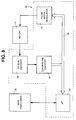
- the Servo Control routine is implemented in an NEC 78312A microcontroller (element 34 in FIG. 8). It receives velocity and feedforward information from the main processor (element 38 in FIG. 8) and controls the servo motors accordingly. This routine is independent of the polyline lookahead, which is performed by the main processor.
- a move command is put into the servo queue for each line segment or vector.
- Each move command has 7 words (16 bits each) containing the following data: ID Format Description A: 8.8 Acceleration VU: 16.0 Ramp up velocity squared VD: 16.0 Ramp down velocity squared VM: 8.8 Maximum velocity DX: S15.0 Relative X movement DY: S15.0 Relative Y movement R: S1.14 Slope: ratio minor/major axis Format designation: si.f, where s is S if signed, followed by i bits of integer, followed by f bits of fraction.
- VU and VD represent the velocity components along the major axis for the forward and reverse profiles respectively when the pen is at the end of each line segment.
- the VU and VD values are actually entered in the servo queue as the square of the velocity. This form is picked to simplify the mathematics used in the servo ramp generator.
- the axes are identified as major and minor, with the major axis being the axis which has the longest movement required for the current vector segment. Note that the major axis will switch between the X (paper) axis and the Y (pen) axis every time the slope goes above or below 45 degrees.
- the example depicted in FIGS. 2 through 4 does not include an axis switch. This should make understanding the concept easier, but it is not required for the algorithm, which will transition smoothly from X major to Y major and vice versa.
- Every line or polyline consists of a ramp up period and a ramp down period. If the line is long enough, it will also have a constant velocity period in the middle. With vector lookahead, each of these periods may include several line segments.
- the Background routine generates this ramp profile in two parts. A copy of the Background routine is annexed as pages A1 to A13.
- the first part generates the forward or ramp up profile. This determines the maximum velocity and acceleration which can be achieved at each segment without regard for getting back to zero velocity at the end of the polyline.
- the forward profile routine generates all database values except VD.
- VD The VU values it generates will be a profile that ramps up to maximum velocity, but never ramps back down again. It will however, include velocity restrictions required due to direction change. These will be a step down followed by another ramp up.
- VD velocity
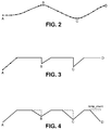
- the exemplary curved polyline shown in FIG. 2 is defined by many points, four of which are labeled by the letters A, B, C, and D.
- the boundary conditions are that the pen must have zero velocity at points A and D. Also it is understood that the pen must have a velocity at the points of greatest curvature, i.e., B and C, which is less than the velocity along substantially straight portions of the polyline to ensure accurate plotting.
- a velocity profile is determined which satisfies all of these conditions in accordance with the method of the invention.
- Such a velocity profile is shown in FIG. 4.
- the pen velocity is ramped up from the starting point A and from the points of greatest curvature B and C, and the pen velocity is ramped down as points B, C and D are approached.
- the VM value is the maximum velocity attainable at a given point on the polyline for the major axis. This will be constrained by the slope of the polyline at that given point if constant pen velocity is enabled. In the case of the preferred embodiment, the VM value will also be constrained by the velocity limits for the respective axes.
- the VU value is the major axis velocity which may be attained at the end of a line segment or vector without regard for ramping back down to a stop.
- FIG. 3 is a graph showing the VU values for each of the points along the polyline depicted in FIG. 2. Assuming N vectors make up the polyline, then the VU value at the end of the n-th vector can he written as VU(n), where 0 ⁇ n ⁇ N, and n and N are integers.
- the velocity VU is limited so that the normal acceleration of the minor axis is less than 3/4 of the acceleration limit for the minor axis. Therefore at least 1/4 of the total minor axis acceleration is available for linear acceleration.
- the VU value is thus limited by the linear acceleration, maximum velocity, and segment length as follows:
- the major axis acceleration limit A is then calculated, so that the major and minor axis capabilities are not exceeded.
- the normal acceleration i.e., acceleration due to direction change
- the minor axis limit it is assured that at least 1/4 of the capabilities are available for linear acceleration (i.e., acceleration not due to direction change). Since the normal acceleration is low at low velocities, most of the acceleration capability is available for linear acceleration at the beginning of the polyline, where the pen will be moving slowly. The acceleration is the same whether the pen velocity is being ramped up or ramped down.
- DX and DY are 16-bit values representing relative X and Y displacement. DX and DY are limited to 16 bits to simplify the math and because with the vector lookahead, longer moves may be broken into multiple shorter moves with no penalty in throughput.
- the slope R of each vector is saved in the table since it is used both in the background routine and the interrupt routine. By storing R, it need not be recalculated by the Interrupt routine.
- the second part i.e., the reverse profile calculation, is performed by the reverse_ramp routine.
- FIG. 4 is a graph showing the VD values for each of the points along the polyline depicted in FIG. 2.
- the number of segments for which this calculation is done is equal to the sum of the in_count and ramp_count registers.
- the in_count register stores the number of segments which have been added since the previous reverse profile calculation.
- the ramp_count register stores the number of segments which were needed to ramp down to zero in the previous reverse profile calculation.
- the contents of the in_count register are added to the contents of the vec_cmndcnt register, which stores the number of segments which the interrupt routine can access.
- the calculation of the reverse profile is scheduled based on various conditions. Any time a string of vectors is broken by a pen up condition or a sharp change in direction occurs, the flush routine is called. This routine determines the ramping down of velocity necessary to arrive at the detected condition, and then clears the ramp_count, so that future reverse profile calculations by the reverse_ramp routine will not go past this point. The reverse profile calculation is also performed if the queue is completely full, if a large number of vertices have been added since the last reverse profile calculation, or if the servo is getting close to catching up to the ramp down point of the previous reverse profile.
- the scheduling of the reverse_ramp routine is based on comparing the number of commands in the servo queue with various threshold limits. It uses the following variables:
- the Interrupt routine is executed by the Motorola 68000 microprocessor once every millisecond to produce a new velocity value for the servo controller, i.e., the NEC 78312A micro-controller. This routine is highly optimized in assembly language. A copy of the Interrupt routine is annexed as pages B1 to B8.
- the Interrupt routine has three basic parts associated with vector lookahead: (1) major axis velocity ramp control; (2) minor axis velocity ratio; and (3) velocity filter.
- the ramp control uses the variable vtest as a control variable.
- the VD value is vf ⁇ vf, and s is the larger of DX and DY.
- vtest is used to determine if a ramp up or ramp down should occur.
- the resultant velocity is then subtracted from s, and used to incrementally update vtest.
- the velocity has 8 bits of fraction.
- the minor axis velocity is ratioed by R from the major axis velocity.
- the variable rem is used to save the remainder from one update to the next, so that this can be added in to prevent truncation loss (the integral of the velocities must equal DX and DY).
- the velocities are filtered using an incremental implementation of a double integrating filter.
- vf vf + af (16)
- these variables have an additional 4 bits of fraction (due to the divisor of 16 in the filter equation) for a total of 12 fractional bits.
- We use a rotating buffer of 8 locations to save the last 8 raw values for each axis velocity. The oldest value is added into the af values before the new v0 is calculated, so that v8 can be overwritten in the buffer.
- the Interrupt routine also processes other commands which are distinguished from the move commands by the sign of the first word.
- the A value in the move is always positive, so the first word of all other commands is the negative of the command index.
- These commands are all padded to occupy 7 words, so that they are the same size as the move commands. These commands are:
- the servo control is independent of the lookahead algorithm. It uses the velocity values for each axis to control the servo motors.
- FIG. 8 is a general depiction of the circuitry for controlling the motors, although to simplify the description, the motor controller 26 will be described in conjunction with only motor 14, which controls movement of the pen.
- An optical encoder 28 coupled to motor 14 outputs pulses at regular angular intervals of rotation of the motor.
- the encoder output represents the Y component of the pen velocity.
- the encoder output is received by quadrature counter 30 and then transmitted to microprocessor 34 in an acceptable form along data bus 36.
- the microprocessor 34 calculates and outputs an 8-bit word P(z), representing one of 256 discrete effective voltages, to the pulse width modulator 32.
- the microprocessor 34 has a 4-kHz sample rate timebase; the quadrature counter 30 and pulse width modulator 32 are respectively read from and written into at the 4-kHz rate.
- the motor 14 is a variable dc motor that is controlled by supplying a 20-kHz waveform with a variable duty cycle at a 20-V level. For example, to drive the motor at an average voltage of 2 V, the duty cycle must equal 10%; if an average voltage of 10 V is desired, the duty cycle must be increased to 50%.
Landscapes
- Engineering & Computer Science (AREA)
- General Engineering & Computer Science (AREA)
- Physics & Mathematics (AREA)
- General Physics & Mathematics (AREA)
- Theoretical Computer Science (AREA)
- Character Spaces And Line Spaces In Printers (AREA)
Applications Claiming Priority (2)
| Application Number | Priority Date | Filing Date | Title |
|---|---|---|---|
| US67515091A | 1991-03-26 | 1991-03-26 | |
| US675150 | 1991-03-26 |
Publications (2)
| Publication Number | Publication Date |
|---|---|
| EP0505922A2 true EP0505922A2 (de) | 1992-09-30 |
| EP0505922A3 EP0505922A3 (de) | 1994-04-06 |
Family
ID=24709264
Family Applications (1)
| Application Number | Title | Priority Date | Filing Date |
|---|---|---|---|
| EP92104754A Withdrawn EP0505922A2 (de) | 1991-03-26 | 1992-03-19 | Gerät und Verfahren zum Plotten mit Polygenzug-Vektorvorhersage |
Country Status (3)
| Country | Link |
|---|---|
| EP (1) | EP0505922A2 (de) |
| JP (1) | JPH0585096A (de) |
| CA (1) | CA2063975A1 (de) |
Family Cites Families (3)
| Publication number | Priority date | Publication date | Assignee | Title |
|---|---|---|---|---|
| US3609319A (en) * | 1968-12-03 | 1971-09-28 | Electronic Associates | Digital plotter in which plotting speed is optimized in terms of a curve-fitting technique |
| GB1419830A (en) * | 1973-03-01 | 1975-12-31 | Cincinnati Milacron Inc | Pulse generator for a numerical control system |
| US3893616A (en) * | 1973-11-23 | 1975-07-08 | California Computer Products | Speed control for electromechanical plotters |
-
1992
- 1992-03-19 EP EP92104754A patent/EP0505922A2/de not_active Withdrawn
- 1992-03-25 CA CA 2063975 patent/CA2063975A1/en not_active Abandoned
- 1992-03-26 JP JP6828392A patent/JPH0585096A/ja not_active Withdrawn
Also Published As
| Publication number | Publication date |
|---|---|
| JPH0585096A (ja) | 1993-04-06 |
| CA2063975A1 (en) | 1992-09-27 |
| EP0505922A3 (de) | 1994-04-06 |
Similar Documents
| Publication | Publication Date | Title |
|---|---|---|
| EP0226450B1 (de) | Druckkopfmotorregelsystem für einen Drucker mit bewegendem Druckkopf | |
| JPH07102722B2 (ja) | 印刷ヘッド・モータ制御システム | |
| US5073748A (en) | Method for limiting the rate-of-change of acceleration in numerical driving systems | |
| EP0089156A1 (de) | Verfahren und Vorrichtung zur Steuerung der Beschleunigung und Abbremsung | |
| US5070287A (en) | Method for a numerical positioning control system | |
| EP0858626A1 (de) | Regelung mit hilfe von einem soll-wert generator | |
| US4220221A (en) | Method and apparatus for producing a speed pattern for an elevator car or similar vehicle | |
| US4169991A (en) | Variable print speed control | |
| EP0505922A2 (de) | Gerät und Verfahren zum Plotten mit Polygenzug-Vektorvorhersage | |
| EP0388089A2 (de) | Bildverarbeitungsgerät | |
| EP0585581B1 (de) | Druckwagenregler für einen Drucker | |
| US6554395B2 (en) | Print head servo and velocity controller with non-linear compensation | |
| US4529325A (en) | Technique for compensation for bandwidth limitations of microprocessor utilized for serial printer control | |
| US4506331A (en) | Numerical control method | |
| US5291114A (en) | Method of and apparatus for controlling a sheet feeding motor used in a printer | |
| JPH05127753A (ja) | サーボモータの加減速運転制御方法 | |
| JPH1049234A (ja) | 機器の位置決め方法及び装置 | |
| EP0099977B1 (de) | Digitales Servosystem für Motorsteuerung | |
| US5917301A (en) | Method for generating a motion profile of a motor | |
| JPS57118916A (en) | Air flow rate control apparatus of car air conditioner | |
| JPS5871183A (ja) | キヤリツジ速度制御方式 | |
| JP3161621B2 (ja) | ステップモータの運転方法 | |
| JPH05187894A (ja) | ペン書き記録計のペン制御装置 | |
| JP2004139531A (ja) | サーボ装置の位置指令補間方法 | |
| Van Pelt | Microprocessor controlled tape motion |
Legal Events
| Date | Code | Title | Description |
|---|---|---|---|
| PUAI | Public reference made under article 153(3) epc to a published international application that has entered the european phase |
Free format text: ORIGINAL CODE: 0009012 |
|
| AK | Designated contracting states |
Kind code of ref document: A2 Designated state(s): AT BE CH DE DK ES FR GB GR IT LI LU MC NL PT SE |
|
| PUAL | Search report despatched |
Free format text: ORIGINAL CODE: 0009013 |
|
| AK | Designated contracting states |
Kind code of ref document: A3 Designated state(s): AT BE CH DE DK ES FR GB GR IT LI LU MC NL PT SE |
|
| PUAF | Information related to the publication of a search report (a3 document) modified or deleted |
Free format text: ORIGINAL CODE: 0009199SEPU |
|
| PUAL | Search report despatched |
Free format text: ORIGINAL CODE: 0009013 |
|
| D17D | Deferred search report published (deleted) | ||
| AK | Designated contracting states |
Kind code of ref document: A3 Designated state(s): AT BE CH DE DK ES FR GB GR IT LI LU MC NL PT SE |
|
| K1C3 | Correction of patent application (complete document) published |
Effective date: 19920930 |
|
| STAA | Information on the status of an ep patent application or granted ep patent |
Free format text: STATUS: THE APPLICATION IS DEEMED TO BE WITHDRAWN |
|
| 18D | Application deemed to be withdrawn |
Effective date: 19940401 |