EP0505688B2 - Commande de machine à déplacement positif d'une transmission hydrostatique-mécanique manoeuvrable sous charge - Google Patents
Commande de machine à déplacement positif d'une transmission hydrostatique-mécanique manoeuvrable sous charge Download PDFInfo
- Publication number
- EP0505688B2 EP0505688B2 EP92101406A EP92101406A EP0505688B2 EP 0505688 B2 EP0505688 B2 EP 0505688B2 EP 92101406 A EP92101406 A EP 92101406A EP 92101406 A EP92101406 A EP 92101406A EP 0505688 B2 EP0505688 B2 EP 0505688B2
- Authority
- EP
- European Patent Office
- Prior art keywords
- volume
- clutch
- new
- leakage
- dvalt
- Prior art date
- Legal status (The legal status is an assumption and is not a legal conclusion. Google has not performed a legal analysis and makes no representation as to the accuracy of the status listed.)
- Expired - Lifetime
Links
Images

Classifications
-
- F—MECHANICAL ENGINEERING; LIGHTING; HEATING; WEAPONS; BLASTING
- F16—ENGINEERING ELEMENTS AND UNITS; GENERAL MEASURES FOR PRODUCING AND MAINTAINING EFFECTIVE FUNCTIONING OF MACHINES OR INSTALLATIONS; THERMAL INSULATION IN GENERAL
- F16H—GEARING
- F16H61/00—Control functions within control units of change-speed- or reversing-gearings for conveying rotary motion ; Control of exclusively fluid gearing, friction gearing, gearings with endless flexible members or other particular types of gearing
- F16H61/38—Control of exclusively fluid gearing
- F16H61/40—Control of exclusively fluid gearing hydrostatic
- F16H61/46—Automatic regulation in accordance with output requirements
- F16H61/462—Automatic regulation in accordance with output requirements for achieving a target speed ratio
-
- F—MECHANICAL ENGINEERING; LIGHTING; HEATING; WEAPONS; BLASTING
- F16—ENGINEERING ELEMENTS AND UNITS; GENERAL MEASURES FOR PRODUCING AND MAINTAINING EFFECTIVE FUNCTIONING OF MACHINES OR INSTALLATIONS; THERMAL INSULATION IN GENERAL
- F16H—GEARING
- F16H47/00—Combinations of mechanical gearing with fluid clutches or fluid gearing
- F16H47/02—Combinations of mechanical gearing with fluid clutches or fluid gearing the fluid gearing being of the volumetric type
- F16H47/04—Combinations of mechanical gearing with fluid clutches or fluid gearing the fluid gearing being of the volumetric type the mechanical gearing being of the type with members having orbital motion
-
- F—MECHANICAL ENGINEERING; LIGHTING; HEATING; WEAPONS; BLASTING
- F16—ENGINEERING ELEMENTS AND UNITS; GENERAL MEASURES FOR PRODUCING AND MAINTAINING EFFECTIVE FUNCTIONING OF MACHINES OR INSTALLATIONS; THERMAL INSULATION IN GENERAL
- F16H—GEARING
- F16H61/00—Control functions within control units of change-speed- or reversing-gearings for conveying rotary motion ; Control of exclusively fluid gearing, friction gearing, gearings with endless flexible members or other particular types of gearing
- F16H61/38—Control of exclusively fluid gearing
- F16H61/40—Control of exclusively fluid gearing hydrostatic
- F16H61/46—Automatic regulation in accordance with output requirements
-
- F—MECHANICAL ENGINEERING; LIGHTING; HEATING; WEAPONS; BLASTING
- F16—ENGINEERING ELEMENTS AND UNITS; GENERAL MEASURES FOR PRODUCING AND MAINTAINING EFFECTIVE FUNCTIONING OF MACHINES OR INSTALLATIONS; THERMAL INSULATION IN GENERAL
- F16H—GEARING
- F16H37/00—Combinations of mechanical gearings, not provided for in groups F16H1/00 - F16H35/00
- F16H37/02—Combinations of mechanical gearings, not provided for in groups F16H1/00 - F16H35/00 comprising essentially only toothed or friction gearings
- F16H37/06—Combinations of mechanical gearings, not provided for in groups F16H1/00 - F16H35/00 comprising essentially only toothed or friction gearings with a plurality of driving or driven shafts; with arrangements for dividing torque between two or more intermediate shafts
- F16H37/08—Combinations of mechanical gearings, not provided for in groups F16H1/00 - F16H35/00 comprising essentially only toothed or friction gearings with a plurality of driving or driven shafts; with arrangements for dividing torque between two or more intermediate shafts with differential gearing
- F16H37/0833—Combinations of mechanical gearings, not provided for in groups F16H1/00 - F16H35/00 comprising essentially only toothed or friction gearings with a plurality of driving or driven shafts; with arrangements for dividing torque between two or more intermediate shafts with differential gearing with arrangements for dividing torque between two or more intermediate shafts, i.e. with two or more internal power paths
- F16H37/084—Combinations of mechanical gearings, not provided for in groups F16H1/00 - F16H35/00 comprising essentially only toothed or friction gearings with a plurality of driving or driven shafts; with arrangements for dividing torque between two or more intermediate shafts with differential gearing with arrangements for dividing torque between two or more intermediate shafts, i.e. with two or more internal power paths at least one power path being a continuously variable transmission, i.e. CVT
- F16H2037/088—Power-split transmissions with summing differentials, with the input of the CVT connected or connectable to the input shaft
- F16H2037/0886—Power-split transmissions with summing differentials, with the input of the CVT connected or connectable to the input shaft with switching means, e.g. to change ranges
-
- Y—GENERAL TAGGING OF NEW TECHNOLOGICAL DEVELOPMENTS; GENERAL TAGGING OF CROSS-SECTIONAL TECHNOLOGIES SPANNING OVER SEVERAL SECTIONS OF THE IPC; TECHNICAL SUBJECTS COVERED BY FORMER USPC CROSS-REFERENCE ART COLLECTIONS [XRACs] AND DIGESTS
- Y10—TECHNICAL SUBJECTS COVERED BY FORMER USPC
- Y10T—TECHNICAL SUBJECTS COVERED BY FORMER US CLASSIFICATION
- Y10T74/00—Machine element or mechanism
- Y10T74/19—Gearing
- Y10T74/19149—Gearing with fluid drive
-
- Y—GENERAL TAGGING OF NEW TECHNOLOGICAL DEVELOPMENTS; GENERAL TAGGING OF CROSS-SECTIONAL TECHNOLOGIES SPANNING OVER SEVERAL SECTIONS OF THE IPC; TECHNICAL SUBJECTS COVERED BY FORMER USPC CROSS-REFERENCE ART COLLECTIONS [XRACs] AND DIGESTS
- Y10—TECHNICAL SUBJECTS COVERED BY FORMER USPC
- Y10T—TECHNICAL SUBJECTS COVERED BY FORMER US CLASSIFICATION
- Y10T74/00—Machine element or mechanism
- Y10T74/19—Gearing
- Y10T74/19555—Varying speed ratio
Definitions
- the invention relates to a method for controlling a hydrostatic variable transmission of a hydrostatic-mechanically stepless power-split power shift transmission in which a displacement volume is actuated after switching on a clutch of a new gear, taking into account a leakage volume with regard to a theoretical displacement volume, after which the clutch of the still active, previously effective Ganges is separated.
- the problem is solved by the features contained in claim 1.
- the new displacement volume is determined in each case from the old leakage volume in accordance with different hydraulic pressure ratios in the adjusting gear before and after the switching operation, the setting of the new displacement volume with respect to the theoretical displacement volume taking place according to a new leakage volume which is determined from the old leakage volume in accordance with the hydraulic pressure ratios.
- the displacement volume is carried out by means of a swivel adjustment of an abutment, which is carried out in an electrically controlled manner by means of a proportional hydraulic adjusting device.
- the displacement machine In a continuously variable, hydrostatically power-split transmission, the displacement machine is used in an additive manner to transmit power before shifting up a gear stage and subtractively after shifting into higher gear.
- theoretically synchronous speeds are specified on the clutches to be engaged and disengaged so that the clutch of the new gear is switched on smoothly and the clutch of the previous gear is disengaged smoothly thereafter.
- the hydrostatic transmission is controlled in such a way that the leakage losses are also covered before the new gear is engaged to establish synchronous operation on the clutch.
- the swashplate setting which determines the displacement volume, is not made symmetrically to the neutral position, but with different correction angles that are adapted to the respective relative leakage losses and balance them out.
- the power flow in the hydrostatic system changes from additive power when changing gear (the adjustment unit is the pump and the constant unit is the motor) to reactive power (the constant unit is the pump and the adjustment unit is the motor).
- the high and low pressure change between the two connecting lines of the units and the high pressure theoretically increases by the factor of the ratio of the gears.
- the high pressure and the amount of leakage oil in the hydrostatic assembly are approximately proportional to one another.
- a constant leakage oil change factor k can therefore be assumed for each load.
- a control circuit is used to adjust the displacement volume, to which a position signal of the actuating device is supplied as an actual signal. It is further provided that speed signals are taken from the input and output shafts of the hydrostatic transmission unit in a known manner. As a result, by observing the speed ratios known for the individual gears, the engagement of the next desired gear takes place with synchronism on the clutch. The respective old actual position signal is obtained, the size of which results from the theoretical displacement volume and the old leakage oil loss. Together with the theoretical actual position signal, a new target position signal to be specified for the control is formed so that the new leakage oil losses are taken into account. When the control process initiated in this way is then completed, the clutch of the previous gear is disengaged and the gear is now continued to run by specifying the displacer volume further changed.
- This control also provides an adaptation to the leak behavior of the device, which changes with ongoing operation, which is dependent on the temperature of the hydraulic oil and the actuating unit and which changes with the load.
- the determination of the leakage oil losses at the beginning of each switching operation and the pre-calculation of the losses after the operation and taking them into account when determining the setpoint automatically includes all ongoing changes in the operating conditions.
- Fig. 1 shows a hydrostatic-mechanical power split power shift transmission, the hydrostatic branch of which consists of the hydrostatic actuator (HG).
- HG hydrostatic actuator
- ST electronic control device
- HGZ position-proportional hydraulic control cylinder
- HV electric-hydraulic control valve pair
- the presence of this speed ratio is determined from the signals from the speed sensors (S1, S2) in the electronic control device (ST). is determined, actuated by the control device (ST), the electrohydraulic third-gear valve (V3), which hydraulically engages the third-gear clutch (K3), the determined speed ratio ensuring that the transmission parts of the clutch (K3) third gear before synchronizing.
- the proportional device (HGZ) is acted upon by the control device (ST) via the electrohydraulic control valve (HGV) in such a way that it is corrected according to the new leakage losses, so that no torque is transmitted to the moving clutch claws of the clutch (K2) of the second gear transmission becomes.
- the control device (ST) switches off the second-gear valve (V2) and thereby disengages the second-gear clutch (K2) hydraulically without jerking by switching off the associated controllable valve (V2).
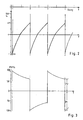
- Fig. 3 shows the pressure conditions in the hydrostatic branch.
- the pressures (P1) and (P2) on both sides of the switching point are related to each other like the control ratio.
- this is fed with a predeterminable current from the control device (ST).
- This current is preferably reported back to the control device (ST) by a current sensor (IS), so that the current strength reported in the presence of synchronous conditions on a clutch to be closed can be stored there as a value of the position signal because of its proportionality and can later be evaluated as a default value.
- IS current sensor
- a position indicator e.g. of a potentiometer (P) on the wiper side
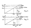
- the dependence of the displacer volume and the associated positions of the control means is shown schematically, ie enlarged in the switching range of the displacer volume when shifting up.
- the old displacer volume (Valt) is larger than the theoretical displacer volume (Vth) by the leakage volume (DValt).
- the new displacer volume (Vneu), in which the old gearbox is load-free, is smaller by a leakage volume difference (DValt xk) than the theoretical displacer volume (Vth) by the leakage volume factor (k).
- the old and new settings (Salt, Sneu) are higher and lower than the theoretical position (Sth) by a smaller or a larger amount.
- the leakage volume factor is in principle greater than 1, since different pressure conditions prevail in the old and new condition, which lead to the differences. As you can see, this gives the formula (1).
- the leakage conditions change during operation, i.e. with different loads, e.g. with train or push operation, i.e. during braking, and can change with the temperature
- the respective values of the position sensor signal (Salt, Salt ') which are in the synchronous case with only one clutch engaged, are stored as the position setpoint signals to be specified for the setting control, so that the upshift signal (Salt) serves as the target signal (Sneu ') when downshifting and the signal (Salt') when downshifting serves as the target signal (Sneu) when upshifting.
- a target signal specification which adapts even further to changing conditions is achieved when a determined synchronous position (Salt, Salt ') is related to the corresponding stored previous synchronized position (Sg, Sg') and by means of the relationship via the leakage volume factor k the associated new one Decoupling position (Sneu, Sneu ') is calculated from the stored uncoupling position (Sg, Sg').
Landscapes
- Engineering & Computer Science (AREA)
- General Engineering & Computer Science (AREA)
- Mechanical Engineering (AREA)
- Control Of Transmission Device (AREA)
Claims (2)
- Dispositif de commande d'un engrenage de réglage hydrostatique (HG) d'une transmission hydrostaticomécanique à réglage continu avec division de puissance et manoeuvrable sous charge, dans le cadre duquel un volume de déplacement (Vneu, Vneu') est amorcé après chaque couplage d'un embrayage (K2, K3) d'une nouvelle vitesse et compte tenu d'un volume de fuite (DValt, DValt') se rapportant à un volume de déplacement théorique (Vth), ce après quoi l'embrayage (K3, K2) de la vitesse précédente, encore coactive, est désaccouplé, dans lequel
le nouveau volume de déplacement (Vneu, Vneu') est déterminé, avant et après chaque opération de couplage, à partir de l'ancien volume de fuite respectif (DValt, DValt'), conformément aux différentes conditions de pression hydraulique dans l'engrenage de réglage (HG), le réglage du nouveau volume de déplacement (Vneu, Vneu') se rapportant au volume de déplacement théorique (Vth) étant effectué selon un nouveau volume de fuite (DVneu, DVneu'), qui est déterminé sur la base de l'ancien volume de fuite (DValt, DValt') en fonction des conditions de pression hydraulique, moyennant quoi l'engrenage de réglage (HG) est raccordé, commandé, à une soupape proportionnelle (HGV), qui est soumise à l'action d'un jeu de soupapes de commande électro-hydrauliques, soumis à l'action d'un dispositif de commande électronique (ST), qui excite, par programme de commande, conformément au procédé, le jeu de soupapes de commande et les embrayages (K2, K3) à l'aide de soupapes électro-hydrauliques (V3, V2), moyennant quoi la soupape proportionnelle (HGV) est soumise, par le dispositif de commande (ST) à un courant prédéterminable, proportionnellement auquel elle est, chaque fois, réglée ou qu'un détecteur de position (P) est coordonné à la soupape proportionnelle (HGV) ou à l'engrenage de réglage (HG), le signal de position de ce détecteur étant conduit au dispositif de commande (ST) et servant, sous forme de signal de rétroactif, au réglage du volume de déplacement déterminé conformément au procédé, et moyennant quoi l'arbre d'entrée et l'arbre de sortie sont équipés de détecteurs tachométriques (S1, S2), dont les signaux, lancés au dispositif de commande (ST) sont contrôlés chacun aux fins de détection d'un état de synchronisation à un embrayage (K2, K3) à fermer, une valeur respective (as, as') du signal de position courant ou potentiomètre (Salt, Salt') afférent étant mémorisée et servant, directement ou indirectement, de nouveau signal de position de consigne (Sneu', Sneu) lors de chaque renversement de vitesse, c'est-à-dire lors de la séparation du même embrayage (K2, K3). - Dispositif selon la revendication 1, caractérisé en ce qu'à l'état de synchronisation, le signal de position respectif (Salt, Salt') est soustrait de la valeur afférente (Sg, Sg'), mémorisée jusqu'à présent, et que la nouvelle position de consigne (Sneu', Sneu) est calculée à partir de la différence (D, D') ainsi obtenue, compte tenu du facteur de volume de fuite (k), en provenance de l'autre valeur (Sg', Sg) respectivement mémorisée.
Applications Claiming Priority (2)
| Application Number | Priority Date | Filing Date | Title |
|---|---|---|---|
| DE4109884A DE4109884A1 (de) | 1991-03-26 | 1991-03-26 | Steuerung einer verdraengermaschine eines hydrostatisch-mechanischen lastschaltgetriebes |
| DE4109884 | 1991-03-26 |
Publications (3)
| Publication Number | Publication Date |
|---|---|
| EP0505688A1 EP0505688A1 (fr) | 1992-09-30 |
| EP0505688B1 EP0505688B1 (fr) | 1994-12-14 |
| EP0505688B2 true EP0505688B2 (fr) | 1997-02-05 |
Family
ID=6428223
Family Applications (1)
| Application Number | Title | Priority Date | Filing Date |
|---|---|---|---|
| EP92101406A Expired - Lifetime EP0505688B2 (fr) | 1991-03-26 | 1992-01-29 | Commande de machine à déplacement positif d'une transmission hydrostatique-mécanique manoeuvrable sous charge |
Country Status (3)
| Country | Link |
|---|---|
| US (1) | US5207736A (fr) |
| EP (1) | EP0505688B2 (fr) |
| DE (2) | DE4109884A1 (fr) |
Families Citing this family (18)
| Publication number | Priority date | Publication date | Assignee | Title |
|---|---|---|---|---|
| EP0557700B1 (fr) * | 1987-05-12 | 1995-08-09 | Friedrich Prof. Dr.-Ing. Jarchow | Boîte de vitesse hydrostatique-mécanique à réglage continu |
| GB2285842B (en) * | 1992-10-06 | 1997-04-16 | Bamford Excavators Ltd | Infinitely variable transmission with power splitting |
| GB9307821D0 (en) * | 1993-04-15 | 1993-06-02 | Greenwood Christopher J | Improvements in or relating to continuously-variable-ratio transmissions |
| US5683322A (en) * | 1993-04-21 | 1997-11-04 | Meyerle; Michael | Continuous hydrostatic-mechanical branch power split transmission particularly for power vehicles |
| DE4433488A1 (de) * | 1994-09-20 | 1996-03-21 | Claas Ohg | Steuerung einer Verdrängermaschine eines hydrostatisch-mechanischen Lastschaltgetriebes |
| DE19513032C1 (de) * | 1995-04-06 | 1996-08-14 | Brueninghaus Hydromatik Gmbh | Vorrichtung zum Verstellen des Fördervolumens einer Hydropumpe |
| US5575735A (en) * | 1995-04-06 | 1996-11-19 | Caterpillar Inc. | Integrated power transmitting system |
| US5682315A (en) * | 1995-05-31 | 1997-10-28 | Caterpillar Inc. | Method and system for controlling a split torque transmission |
| EP0897493B1 (fr) * | 1996-04-30 | 2000-03-15 | Steyr-Daimler-Puch Aktiengesellschaft | Procede pour commander les embrayages d'une transmission a division de puissance mecano-hydrostatique |
| JP3796916B2 (ja) * | 1997-08-25 | 2006-07-12 | マツダ株式会社 | トロイダル式無段変速機の制御装置 |
| US6042502A (en) * | 1999-04-08 | 2000-03-28 | Caterpillar Inc. | Method and apparatus for generating velocity commands in response to rapid changes in operator inputs |
| DE10001916A1 (de) * | 2000-01-19 | 2001-07-26 | Zahnradfabrik Friedrichshafen | Hydraulikkreislauf in einem stufenlos verstellbaren Getriebe |
| DE10001915A1 (de) * | 2000-01-19 | 2001-07-26 | Zahnradfabrik Friedrichshafen | Leistungsverzweigungsgetriebe |
| US6402660B1 (en) * | 2000-09-26 | 2002-06-11 | Caterpillar Inc. | Apparatus and method for adaptively shifting between ranges in a continuously variable transmission |
| DE10125259A1 (de) * | 2001-05-23 | 2002-11-28 | Zahnradfabrik Friedrichshafen | Getriebe mit einer bedarfsorientierten Ölversorgung |
| AT512941B1 (de) * | 2012-10-08 | 2013-12-15 | Avl List Gmbh | Getriebe |
| DE102014205039A1 (de) * | 2014-03-19 | 2015-09-24 | Robert Bosch Gmbh | Stufenloses Getriebe mit nichtsynchroner Kupplungsbetätigung |
| US9303760B2 (en) * | 2014-06-06 | 2016-04-05 | Cnh Industrial America Llc | System and method of controlling shifts of an electronically controlled mechanical transmission of a vehicle |
Family Cites Families (13)
| Publication number | Priority date | Publication date | Assignee | Title |
|---|---|---|---|---|
| US3212358A (en) * | 1962-01-16 | 1965-10-19 | Lalio George M De | Continuously variable power transmission |
| US3204486A (en) * | 1963-03-06 | 1965-09-07 | Lalio George M De | Infinitely variable power transmission |
| US4309917A (en) * | 1979-12-11 | 1982-01-12 | General Motors Corporation | Transmission and control system |
| DE3667836D1 (de) * | 1986-02-24 | 1990-02-01 | Shimadzu Corp | Hydromechanisches getriebe. |
| DE3713799A1 (de) * | 1987-04-24 | 1988-11-10 | Rexroth Mannesmann Gmbh | Hydrostatisches antriebssystem |
| DE3838767A1 (de) * | 1987-05-12 | 1989-06-08 | Jarchow Friedrich | Stufenlos wirkendes hydrostatisch-mechanisches lastschaltgetriebe mit hoher schaltqualitaet |
| EP0557700B1 (fr) * | 1987-05-12 | 1995-08-09 | Friedrich Prof. Dr.-Ing. Jarchow | Boîte de vitesse hydrostatique-mécanique à réglage continu |
| DE3807599A1 (de) * | 1988-03-08 | 1989-09-28 | Hydromatik Gmbh | Automotive antriebseinrichtung fuer maschinen und fahrzeuge |
| DE3836017A1 (de) * | 1988-10-22 | 1990-04-26 | Man Nutzfahrzeuge Ag | Antriebseinrichtung, insbesondere fuer ein extremgelaendegaengiges radfahrzeug |
| DE3903877C1 (fr) * | 1989-02-10 | 1990-09-13 | Friedrich Prof. Dr.-Ing. 4300 Essen De Jarchow | |
| CA2018248A1 (fr) * | 1989-06-07 | 1990-12-07 | Clyde W. Shearman | Anticorps monoclonaux contre le recepteur alpha-beta de cellules t humaines, leur production et leur utilisation |
| EP0444472A3 (en) * | 1990-02-13 | 1992-01-02 | Michael Meyerle | Control system, particularly for motor vehicle |
| DE4021643A1 (de) * | 1990-07-06 | 1992-01-16 | Claas Ohg | Hydrostatisch-leistungsverzweigtes mehrgang-lastschaltgetriebe |
-
1991
- 1991-03-26 DE DE4109884A patent/DE4109884A1/de not_active Withdrawn
-
1992
- 1992-01-29 EP EP92101406A patent/EP0505688B2/fr not_active Expired - Lifetime
- 1992-01-29 DE DE59200931T patent/DE59200931D1/de not_active Expired - Fee Related
- 1992-03-26 US US07/858,284 patent/US5207736A/en not_active Expired - Fee Related
Also Published As
| Publication number | Publication date |
|---|---|
| DE4109884A1 (de) | 1992-10-01 |
| EP0505688A1 (fr) | 1992-09-30 |
| EP0505688B1 (fr) | 1994-12-14 |
| US5207736A (en) | 1993-05-04 |
| DE59200931D1 (de) | 1995-01-26 |
Similar Documents
| Publication | Publication Date | Title |
|---|---|---|
| EP0505688B2 (fr) | Commande de machine à déplacement positif d'une transmission hydrostatique-mécanique manoeuvrable sous charge | |
| DE4031570C2 (de) | Anordnung zum selbsttätigen Schalten mittels Druckmittel-Hilfskraft eines Mehrwege-Zahnräderwechselgetriebes | |
| EP0650564B1 (fr) | Ensemble boite de vitesses a disposer entre un moteur d'entrainement et un recepteur | |
| EP0464413B1 (fr) | Transmission hydrostatique-mécanique à division de puissance à vitesses multiples et passages sous couple | |
| DE102004043017B4 (de) | Steuerungssystem eines hydromechanischen Getriebes | |
| DE69110241T2 (de) | Steuerverfahren zum Herunterschalten eines Getriebes im Schiebebetrieb. | |
| DE4424456A1 (de) | Verfahren zum Steuern eines Automatgetriebes | |
| EP0752545B1 (fr) | Entraínement hydrostatique avec transmission étagée reliée en aval | |
| WO2004033246A2 (fr) | Procede de commande des changements de rapports d'une boite couplable sous charge et boite de vitesses couplable sous charge | |
| EP0545298A1 (fr) | Train d'entraînement à contrôle hydraulique pour véhicules | |
| EP0703386B1 (fr) | Système de commande d'una machine volumétrique d'une transmission hydromécanique à changement de vitesse sous charge | |
| DE3447640C2 (fr) | ||
| WO1998045627A1 (fr) | Accroissement de la spontaneite d'une transmission automatique | |
| DE68929357T2 (de) | Mechanisch-hydraulisches Getriebesystem und Steuerverfahren für Leistungsgetriebe mit einem solchen System | |
| DE19751456A1 (de) | Verfahren zum Schalten eines Doppelkupplungsgetriebes | |
| DE10357500A1 (de) | Elektronisches Steuerungssystem für den Kupplungswechsel in einem Getriebe | |
| EP1482217B1 (fr) | Ensemble de transmission et son procédé de commande | |
| DE2307550A1 (de) | Schaltungsanordnung fuer ein hydraulisches getriebe und nachschaltgetriebe | |
| WO1990002059A1 (fr) | Agencement et procede pour faire fonctionner une unite de transmission a variation continue dans un vehicule a moteur | |
| WO1997024539A1 (fr) | Procede de commande d'une boite de vitesses hydrostatique-mecanique a derivation de puissance dans des positions indeterminees d'embrayage | |
| DE1021251B (de) | Hydraulischer Fahrzeugantrieb | |
| DE3838767C2 (fr) | ||
| DE1812931C3 (de) | Steuervorrichtung für ein automatisch schaltbares Wechselgetriebe für Fahrzeuge, insbesondere Kraftfahrzeuge | |
| DE3926716A1 (de) | Einrichtung und verfahren zum betrieb einer verstellbaren antriebseinheit | |
| DE2629977C3 (de) | Hydrostatischer Stellwandler mit einem Hydromotor, einer Hydropumpe und einem nachgeschalteten Lastschaltgetriebe |
Legal Events
| Date | Code | Title | Description |
|---|---|---|---|
| PUAI | Public reference made under article 153(3) epc to a published international application that has entered the european phase |
Free format text: ORIGINAL CODE: 0009012 |
|
| AK | Designated contracting states |
Kind code of ref document: A1 Designated state(s): DE FR GB IT NL SE |
|
| 17P | Request for examination filed |
Effective date: 19921119 |
|
| 17Q | First examination report despatched |
Effective date: 19940505 |
|
| GRAA | (expected) grant |
Free format text: ORIGINAL CODE: 0009210 |
|
| AK | Designated contracting states |
Kind code of ref document: B1 Designated state(s): DE FR GB IT NL SE |
|
| PG25 | Lapsed in a contracting state [announced via postgrant information from national office to epo] |
Ref country code: NL Effective date: 19941214 |
|
| REF | Corresponds to: |
Ref document number: 59200931 Country of ref document: DE Date of ref document: 19950126 |
|
| ITF | It: translation for a ep patent filed | ||
| PG25 | Lapsed in a contracting state [announced via postgrant information from national office to epo] |
Ref country code: SE Effective date: 19950314 |
|
| GBT | Gb: translation of ep patent filed (gb section 77(6)(a)/1977) |
Effective date: 19950221 |
|
| ET | Fr: translation filed | ||
| NLV1 | Nl: lapsed or annulled due to failure to fulfill the requirements of art. 29p and 29m of the patents act | ||
| PLBI | Opposition filed |
Free format text: ORIGINAL CODE: 0009260 |
|
| 26 | Opposition filed |
Opponent name: STEYR- DAIMLER- PUCH AKTIENGESELLSCHAFT Effective date: 19950907 |
|
| PLBF | Reply of patent proprietor to notice(s) of opposition |
Free format text: ORIGINAL CODE: EPIDOS OBSO |
|
| RAP2 | Party data changed (patent owner data changed or rights of a patent transferred) |
Owner name: CLAAS KOMMANDITGESELLSCHAFT AUF AKTIEN |
|
| PLAW | Interlocutory decision in opposition |
Free format text: ORIGINAL CODE: EPIDOS IDOP |
|
| PLAW | Interlocutory decision in opposition |
Free format text: ORIGINAL CODE: EPIDOS IDOP |
|
| PUAH | Patent maintained in amended form |
Free format text: ORIGINAL CODE: 0009272 |
|
| STAA | Information on the status of an ep patent application or granted ep patent |
Free format text: STATUS: PATENT MAINTAINED AS AMENDED |
|
| 27A | Patent maintained in amended form |
Effective date: 19970205 |
|
| AK | Designated contracting states |
Kind code of ref document: B2 Designated state(s): DE FR GB IT NL SE |
|
| GBTA | Gb: translation of amended ep patent filed (gb section 77(6)(b)/1977) | ||
| ET3 | Fr: translation filed ** decision concerning opposition | ||
| ITF | It: translation for a ep patent filed | ||
| REG | Reference to a national code |
Ref country code: GB Ref legal event code: 732E |
|
| REG | Reference to a national code |
Ref country code: GB Ref legal event code: IF02 |
|
| PGFP | Annual fee paid to national office [announced via postgrant information from national office to epo] |
Ref country code: GB Payment date: 20030113 Year of fee payment: 12 |
|
| PGFP | Annual fee paid to national office [announced via postgrant information from national office to epo] |
Ref country code: FR Payment date: 20030117 Year of fee payment: 12 |
|
| PG25 | Lapsed in a contracting state [announced via postgrant information from national office to epo] |
Ref country code: GB Free format text: LAPSE BECAUSE OF NON-PAYMENT OF DUE FEES Effective date: 20040129 |
|
| GBPC | Gb: european patent ceased through non-payment of renewal fee |
Effective date: 20040129 |
|
| PG25 | Lapsed in a contracting state [announced via postgrant information from national office to epo] |
Ref country code: FR Free format text: LAPSE BECAUSE OF NON-PAYMENT OF DUE FEES Effective date: 20040930 |
|
| REG | Reference to a national code |
Ref country code: FR Ref legal event code: ST |
|
| PG25 | Lapsed in a contracting state [announced via postgrant information from national office to epo] |
Ref country code: IT Free format text: LAPSE BECAUSE OF NON-PAYMENT OF DUE FEES;WARNING: LAPSES OF ITALIAN PATENTS WITH EFFECTIVE DATE BEFORE 2007 MAY HAVE OCCURRED AT ANY TIME BEFORE 2007. THE CORRECT EFFECTIVE DATE MAY BE DIFFERENT FROM THE ONE RECORDED. Effective date: 20050129 |
|
| PGFP | Annual fee paid to national office [announced via postgrant information from national office to epo] |
Ref country code: DE Payment date: 20071204 Year of fee payment: 17 |
|
| PG25 | Lapsed in a contracting state [announced via postgrant information from national office to epo] |
Ref country code: DE Free format text: LAPSE BECAUSE OF NON-PAYMENT OF DUE FEES Effective date: 20090801 |