EP0505313A2 - Vorrichtung zur Herstellung von spiralförmigen Scheiben - Google Patents
Vorrichtung zur Herstellung von spiralförmigen Scheiben Download PDFInfo
- Publication number
- EP0505313A2 EP0505313A2 EP92630015A EP92630015A EP0505313A2 EP 0505313 A2 EP0505313 A2 EP 0505313A2 EP 92630015 A EP92630015 A EP 92630015A EP 92630015 A EP92630015 A EP 92630015A EP 0505313 A2 EP0505313 A2 EP 0505313A2
- Authority
- EP
- European Patent Office
- Prior art keywords
- knife
- blades
- assembly
- blade
- feed
- Prior art date
- Legal status (The legal status is an assumption and is not a legal conclusion. Google has not performed a legal analysis and makes no representation as to the accuracy of the status listed.)
- Withdrawn
Links
Images



Classifications
-
- B—PERFORMING OPERATIONS; TRANSPORTING
- B23—MACHINE TOOLS; METAL-WORKING NOT OTHERWISE PROVIDED FOR
- B23Q—DETAILS, COMPONENTS, OR ACCESSORIES FOR MACHINE TOOLS, e.g. ARRANGEMENTS FOR COPYING OR CONTROLLING; MACHINE TOOLS IN GENERAL CHARACTERISED BY THE CONSTRUCTION OF PARTICULAR DETAILS OR COMPONENTS; COMBINATIONS OR ASSOCIATIONS OF METAL-WORKING MACHINES, NOT DIRECTED TO A PARTICULAR RESULT
- B23Q11/00—Accessories fitted to machine tools for keeping tools or parts of the machine in good working condition or for cooling work; Safety devices specially combined with or arranged in, or specially adapted for use in connection with, machine tools
- B23Q11/12—Arrangements for cooling or lubricating parts of the machine
- B23Q11/126—Arrangements for cooling or lubricating parts of the machine for cooling only
-
- B—PERFORMING OPERATIONS; TRANSPORTING
- B26—HAND CUTTING TOOLS; CUTTING; SEVERING
- B26D—CUTTING; DETAILS COMMON TO MACHINES FOR PERFORATING, PUNCHING, CUTTING-OUT, STAMPING-OUT OR SEVERING
- B26D3/00—Cutting work characterised by the nature of the cut made; Apparatus therefor
- B26D3/10—Making cuts of other than simple rectilinear form
- B26D3/11—Making cuts of other than simple rectilinear form to obtain pieces of spiral or helical form
-
- B—PERFORMING OPERATIONS; TRANSPORTING
- B26—HAND CUTTING TOOLS; CUTTING; SEVERING
- B26D—CUTTING; DETAILS COMMON TO MACHINES FOR PERFORATING, PUNCHING, CUTTING-OUT, STAMPING-OUT OR SEVERING
- B26D7/00—Details of apparatus for cutting, cutting-out, stamping-out, punching, perforating, or severing by means other than cutting
- B26D7/06—Arrangements for feeding or delivering work of other than sheet, web, or filamentary form
- B26D7/0625—Arrangements for feeding or delivering work of other than sheet, web, or filamentary form by endless conveyors, e.g. belts
-
- B—PERFORMING OPERATIONS; TRANSPORTING
- B26—HAND CUTTING TOOLS; CUTTING; SEVERING
- B26D—CUTTING; DETAILS COMMON TO MACHINES FOR PERFORATING, PUNCHING, CUTTING-OUT, STAMPING-OUT OR SEVERING
- B26D7/00—Details of apparatus for cutting, cutting-out, stamping-out, punching, perforating, or severing by means other than cutting
- B26D7/08—Means for treating work or cutting member to facilitate cutting
- B26D7/10—Means for treating work or cutting member to facilitate cutting by heating
-
- B—PERFORMING OPERATIONS; TRANSPORTING
- B26—HAND CUTTING TOOLS; CUTTING; SEVERING
- B26D—CUTTING; DETAILS COMMON TO MACHINES FOR PERFORATING, PUNCHING, CUTTING-OUT, STAMPING-OUT OR SEVERING
- B26D1/00—Cutting through work characterised by the nature or movement of the cutting member or particular materials not otherwise provided for; Apparatus or machines therefor; Cutting members therefor
- B26D1/0006—Cutting members therefor
- B26D2001/0046—Cutting members therefor rotating continuously about an axis perpendicular to the edge
-
- B—PERFORMING OPERATIONS; TRANSPORTING
- B26—HAND CUTTING TOOLS; CUTTING; SEVERING
- B26D—CUTTING; DETAILS COMMON TO MACHINES FOR PERFORATING, PUNCHING, CUTTING-OUT, STAMPING-OUT OR SEVERING
- B26D1/00—Cutting through work characterised by the nature or movement of the cutting member or particular materials not otherwise provided for; Apparatus or machines therefor; Cutting members therefor
- B26D1/0006—Cutting members therefor
- B26D2001/0053—Cutting members therefor having a special cutting edge section or blade section
-
- B—PERFORMING OPERATIONS; TRANSPORTING
- B26—HAND CUTTING TOOLS; CUTTING; SEVERING
- B26D—CUTTING; DETAILS COMMON TO MACHINES FOR PERFORATING, PUNCHING, CUTTING-OUT, STAMPING-OUT OR SEVERING
- B26D1/00—Cutting through work characterised by the nature or movement of the cutting member or particular materials not otherwise provided for; Apparatus or machines therefor; Cutting members therefor
- B26D1/0006—Cutting members therefor
- B26D2001/006—Cutting members therefor the cutting blade having a special shape, e.g. a special outline, serrations
-
- Y—GENERAL TAGGING OF NEW TECHNOLOGICAL DEVELOPMENTS; GENERAL TAGGING OF CROSS-SECTIONAL TECHNOLOGIES SPANNING OVER SEVERAL SECTIONS OF THE IPC; TECHNICAL SUBJECTS COVERED BY FORMER USPC CROSS-REFERENCE ART COLLECTIONS [XRACs] AND DIGESTS
- Y10—TECHNICAL SUBJECTS COVERED BY FORMER USPC
- Y10S—TECHNICAL SUBJECTS COVERED BY FORMER USPC CROSS-REFERENCE ART COLLECTIONS [XRACs] AND DIGESTS
- Y10S83/00—Cutting
- Y10S83/929—Particular nature of work or product
- Y10S83/932—Edible
-
- Y—GENERAL TAGGING OF NEW TECHNOLOGICAL DEVELOPMENTS; GENERAL TAGGING OF CROSS-SECTIONAL TECHNOLOGIES SPANNING OVER SEVERAL SECTIONS OF THE IPC; TECHNICAL SUBJECTS COVERED BY FORMER USPC CROSS-REFERENCE ART COLLECTIONS [XRACs] AND DIGESTS
- Y10—TECHNICAL SUBJECTS COVERED BY FORMER USPC
- Y10T—TECHNICAL SUBJECTS COVERED BY FORMER US CLASSIFICATION
- Y10T83/00—Cutting
- Y10T83/02—Other than completely through work thickness
- Y10T83/0207—Other than completely through work thickness or through work presented
-
- Y—GENERAL TAGGING OF NEW TECHNOLOGICAL DEVELOPMENTS; GENERAL TAGGING OF CROSS-SECTIONAL TECHNOLOGIES SPANNING OVER SEVERAL SECTIONS OF THE IPC; TECHNICAL SUBJECTS COVERED BY FORMER USPC CROSS-REFERENCE ART COLLECTIONS [XRACs] AND DIGESTS
- Y10—TECHNICAL SUBJECTS COVERED BY FORMER USPC
- Y10T—TECHNICAL SUBJECTS COVERED BY FORMER US CLASSIFICATION
- Y10T83/00—Cutting
- Y10T83/202—With product handling means
- Y10T83/2074—Including means to divert one portion of product from another
-
- Y—GENERAL TAGGING OF NEW TECHNOLOGICAL DEVELOPMENTS; GENERAL TAGGING OF CROSS-SECTIONAL TECHNOLOGIES SPANNING OVER SEVERAL SECTIONS OF THE IPC; TECHNICAL SUBJECTS COVERED BY FORMER USPC CROSS-REFERENCE ART COLLECTIONS [XRACs] AND DIGESTS
- Y10—TECHNICAL SUBJECTS COVERED BY FORMER USPC
- Y10T—TECHNICAL SUBJECTS COVERED BY FORMER US CLASSIFICATION
- Y10T83/00—Cutting
- Y10T83/485—Cutter with timed stroke relative to moving work
- Y10T83/494—Uniform periodic tool actuation
- Y10T83/501—With plural tools on a single tool support
-
- Y—GENERAL TAGGING OF NEW TECHNOLOGICAL DEVELOPMENTS; GENERAL TAGGING OF CROSS-SECTIONAL TECHNOLOGIES SPANNING OVER SEVERAL SECTIONS OF THE IPC; TECHNICAL SUBJECTS COVERED BY FORMER USPC CROSS-REFERENCE ART COLLECTIONS [XRACs] AND DIGESTS
- Y10—TECHNICAL SUBJECTS COVERED BY FORMER USPC
- Y10T—TECHNICAL SUBJECTS COVERED BY FORMER US CLASSIFICATION
- Y10T83/00—Cutting
- Y10T83/869—Means to drive or to guide tool
- Y10T83/8789—With simple revolving motion only
- Y10T83/8791—Tool mounted on radial face of rotor
Definitions
- the invention relates to an apparatus for slicing objects, such as potatoes, into helical or spiral-shaped portions.
- the apparatus of each of these patents transports potatoes between a set of top, bottom, and side conveyors to a set of spring biased feed rollers 150, 151, and 152.
- Each potato is then translated horizontally between the feed rollers into contact with a rotating knife assembly 12.
- the knife assembly has two radially oriented rows of horizontally protruding knife blades 180 for scoring the potato, and a vertically oriented blade 182 for severing helical slices from the scored potato.
- the knife assembly of U.S. 4,979,418 (and of a first embodiment disclosed in U.S. 4,926,726) is driven by drive gear 188 which engages the knife assembly's drive teeth 231 (shown in Figure 11 of U.S. 4,926,726).
- the knife assembly is driven by drive belt 360 (shown in Figure 13), which engages teeth 320 of knife assembly member 316.
- the present invention is an improved apparatus for producing helical slices of an object, which includes an improved knife assembly drive means employing water to cool and clean its bearings, an improved knife assembly having knife blades arranged in a spiral pattern to reduce the torque needed to slice objects, and an improved, vertically oriented feed roller and feed chain assembly for translating objects into contact with the knife assembly.
- the invention is an apparatus for producing helical slices of an object.
- potatoes are an important example of an object that can be sliced in accordance with the invention.
- the specification will describe the invention in the context of slicing potatoes, although the claimed invention is not limited to a method or apparatus for slicing potatoes.
- the apparatus of the invention includes a rotatably mounted knife assembly having one or more sets of knife blades arranged in a spiral pattern. Each set of knife blades produces a set of helically shaped potato slices. The spiral arrangement of each blade set reduces the torque needed to slice a potato using the inventive knife assembly.
- the arrangement of scoring and slicing blades in the inventive apparatus produces helical slices in a single, continuous cutting action, rather than by a scoring cutting action followed by a subsequent slicing action to produce helical slices, as in conventional devices such as those described in above-discussed U.S. Patents 4,926,726 and 4,979,418.
- the invention includes two sets of slicing blades, for producing two sets of intertwined helical product slices.
- a curved separator tube which extends downward from the slicing blade area, disentangles the pair of intertwined slices having the smallest radius, as the blade assembly and the separator tube rotates as a unit.
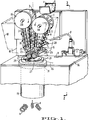
- Figure 1 is a perspective view of a preferred embodiment of the apparatus of the invention.
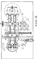
- Figure 2 is a cross-sectional view of the Figure 1 apparatus, taken along line 2-2.
- Figure 3 is a cross-sectional view of the Figure 2 apparatus, taken along line 3-3.
- Figure 4 is a front cross-sectional view of the product feed assembly of the Figure 1 apparatus.
- Figure 5 is a cross-sectional view of a portion of the Figure 4 apparatus, taken along line 5-5 of Figure 4.
- Figure 6 is a is a cross-sectional view of a gear box portion of the Figure 2 apparatus, taken along line 6-6 of Figure 2.
- Figure 7 is a side cross-sectional view of a portion of the Figure 1 apparatus.
- Figure 8 is an exploded perspective view of gear components of the Figure 1 apparatus.
- Figure 9 is an exploded perspective view of the knife assembly of the Figure 1 apparatus.
- Figure 10 is a cross-sectional view of the assembled Figure 9 assembly, taken along line 10-10 of Figure 9.
- Figure 11 is an exploded side view of a portion of the knife assembly of Figure 9.
- Figure 12 is a cross-sectional view of a knife portion of the Figure 11 apparatus, taken along line 12-12 of Figure 11.
- Figure 13 is a cross-sectional view of the knife of Figure 12, taken along line 13-13 of Figure 12.
- Figure 14 is a top view of a portion of the Figure 11 apparatus.
- Figure 15 is a side view of a portion of a knife template, of a type which can be processed (by bending and sharpening) to produce the knife component shown in Figure 14.
- Figure 16 is a top view of an alternative preferred embodiment of a knife assembly, suitable for mounting in the Figure 1 apparatus.
- Figure 17 is a cross-sectional view of the Figure 16 assembly, taken along line 17-17 of Figure 16.
- Figure 18 is a cross-sectional view of a portion of the Figure 16 assembly, taken along line 18-18 of Figure 17.
- Figure 19 is a cross-sectional view of a portion of the Figure 16 assembly, taken along line 19-19 of Figure 17.
- Figure 20 is a perspective view of another alternative preferred embodiment of a knife assembly, suitable for mounting in the Figure 1 apparatus,
- Figure 21 is a cross-sectional view of a portion of Figure 20 assembly, engaged with a potato.
- Figure 22 is a perspective view of a helical slice of the type that can be produced using the Figure 20 assembly.
- Figure 23 is a top view of a portion of the Figure 20 assembly.
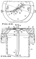
- Figure 24 is a cross-sectional view of a portion of the Figure 23 assembly, taken along line 24-24 of Figure 23.
- the apparatus produces helical slices (such as slices 4) from objects (such as potato 2 on shaker table 1, and potato 3 shown falling between feed chain 5 and gripper chain 7).
- objects such as potato 2 on shaker table 1, and potato 3 shown falling between feed chain 5 and gripper chain 7.
- helical slices such as slices 4
- objects such as potato 2 on shaker table 1, and potato 3 shown falling between feed chain 5 and gripper chain 7.
- unsliced potatoes fall from shaker table 1 they are guided into the space between feed chain 5 and gripper chain 7 by spindles 11 and 13, each potato is gripped by chains 5 and 7 and conveyed downward to set of feed rolls 27.
- Feed chain 5 is mounted around spindle 11 and drive sprocket
- gripper chain 7 is mounted around spindle 13 and drive sprocket 17.
- spindle 13 preferably has a smaller radius than spindle 11, and spindles 11 and 13 are both preferably composed of durable plastic.
- the centerline of spindle 13 is offset vertically above the centerline of spindle 11, so that spindles 11 and 13 act together to divert potatoes 2 from a generally horizontal path to a vertical downward path between chains 5 and 7.
- each potato As each potato is conveyed downward between chains 5 and 7, it is constrained by one of cleats 9 of gripper chain 7 and aligned by guides 6 of feed chain 5, so that it reaches feed rolls 27 in a generally vertical alignment (with its long axis oriented generally vertically).
- Feed rolls 27 are mounted at the ends of rotatable shafts 23 and 25, sprocket 15 is mounted at the end of rotatable shaft 28, and sprocket 17 is mounted at the end of rotatable shaft 26 (shown in Figure 3, but not in Figure 1).
- Each of shafts 23, 25, 26, and 28 is mounted (in a manner to be described below with reference to Figures 2, 3, and 6) with freedom to move horizontally. This freedom to move horizontally permits sprockets 15 and 17 (and rolls 27) to be displaced away from each other when necessary to allow large potatoes to pass between them.
- the teeth of feed rolls 27 grip each potato and force the potato vertically against knife 21. Knife 21 rotates in a horizontal plane to slice each potato forced against it by feed rolls 27.
- the teeth of feed rolls 27 have a triangular cross-section (as shown in Figure 4).
- Such a triangular cross-section in combination with a clearance slot in the center portion of each feed roll (best shown in Figure 2), allows feed rolls 27 to be positioned in very close proximity (i.e., one-sixteenth of an inch or less) to slicing knife 21.
- Knife 21 is mounted on knife carrier 29, which is attached to bearing 31.
- the outer cylindrical surface of bearing 31 has teeth, which engage corresponding teeth of idler gear 35.
- Bearing 31, gear 35, and the other components of the inventive apparatus for driving knife 21, will be described in detail below with reference to Figures 2, 3, 7, and 8.
- Chute 19 is rigidly mounted to frame 36 and its inner diameter is such that it adds a slight drag to the cut helical slices as they disengage from rotating knife 22. This drag against chute or tube 19 will stop the uncut end portion from spinning and breaking off after disengaging feed rolls 27. The result is a completely cut potato.
- the falling slices can be collected in a bin or conveyor belt (not shown in Figure 1).
- Housing 18 (which is shown in phantom view in Figure 1) is removably mounted around the feed assembly of the apparatus (chains 5 and 7 and feed rolls 27) to prevent potato slices from escaping from the area, and to prevent contaminants from reaching the knife area during slicing operations.
- Water line 8 directs a stream of water to the area of sprockets 15 and 17, and feed rolls 27, and water line 9 directs a stream of water to the area of knife 21, to rinse the components in these respective areas when desired.
- housing 18 has a channel extending through its sidewall through which water line 8 can be inserted. Additional water lines 10 and 10a, shown in Figures 2 and 7 but not in Figure 1, supply water to cool and flush gear idler 35 and knife bearing 31 (in a manner to be explained in greater detail below with reference to Figures 2 and 7).
- Gear box 49 (best shown in Fig. 6) includes worm gears for translating the vertical rotation of shaft 47 into counterclockwise rotation of shafts 63a and clockwise rotation of shafts 65a.
- Lubricating oil flows downward through gear box 49, and is forced by pumping screw 49b to recirculate back to the top of gear box 49 through oil line 49a.
- Upper and lower shafts 65a are connected to upper and lower universal joint couplers 65 (shown in Figure 2), and upper and lower shafts 63a are connected to upper and lower universal joint couplers 63 (upper coupler 63 is shown in Figure 3).
- Upper and lower couplers 65 are connected, respectively, to shafts 28 and 25.
- Upper and lower couplers 63 are connected, respectively, to shafts 26 and 23.
- Shafts 28 and 25 are supported by adjustable upper and lower slide blocks 79.
- Shafts 26 and 23 are supported by upper and lower slide blocks 77.
- Each of couplers 63 and 65 transmits rotational motion from one shaft connected thereto to the other shaft connected thereto.
- the inventive apparatus is designed so that shafts 23, 25, 26, and 28 are mounted with freedom to pivot toward each other or away from each other in a horizontal plane (i.e., in the direction of the arrows shown adjacent shafts 26 and 28 in Figure 3, and in the direction of the arrows shown adjacent shafts 23 and 25 in Figure 1) while they rotate.
- mounting member 69 is rigidly connected to shaft 28 and to one end of rigid member 75
- mounting member 71 is rigidly connected to shaft 26 and to one end of rigid member 73.
- Members 69 and 71 are connected together by pivot 67, so that the assembly comprising shaft 26 and members 71 and 73 is free to pivot in a horizontal plane about pivot 67, with respect to the assembly comprising shaft 28 and members 69 and 75.
- a second end of member 73 is attached to slide block 77, and a second end of member 75 is attached to adjustable slide block 79.
- An adjustable screw 78 is attached to each block 79 to limit the minimum distance between that block 79 and the adjacent slide block 77.
- Each pair of adjacent slide blocks 77 and 79 is free to slide toward (and away from) each other along the axis of screw 78 as shafts 26 and 28 pivot, while at the same time shafts 26 and 28 rotate about their respective axes relative to the slide blocks 77 and 79.
- Slide plate 81 (shown in Figures 1, 2, and 3) separates the knife and feed assemblies from the drive assembly.
- Slide plate 81 (which is preferably made of durable plastic) has four horizontally oriented linear openings 81a (one for each of the upper and lower slide blocks 77 and the upper and lower slide blocks 79). Shafts 23, 25, 26, and 28 extend through the openings 81a, and slide blocks 77 and 79 slide along the openings 81a. Openings 81a thus function as linear tracks which constrain the slide blocks to translate along . horizontal linear paths. Slide plate 81 also prevents product fragments from the knife area from contaminating the drive assembly.
- One end of rigid shaft 41 is connected to member 73, and spring 43 is compressed between member 75 and the other end of shaft 41.
- Spring 43 thus biases members 73 and 75 together.
- shafts 26 and 28 are forced apart (for example, by a potato passing between them)
- the outward force exerted on members 73 and 75 by the outward sliding slide blocks 77 and 79 will further compress spring 43.
- spring 43 will relax back to its original length.
- spring 43 relaxes to its original length, it causes members 73 and 75 to push slide blocks 77 and 79 together and to rotate members 69 and 71 about pivot 67 back to their original positions.
- Couplers 63 and 65 are capable of flexing in a horizontal plane to accommodate pivoting motion of shafts 26 and 28 with respect to fixedly mounted gear box 49.
- Adjustable screws 80 limit the pivoting motion of member 71. Screws 80 can be independently advanced or retracted to control the angular range through which member 71 is free to pivot.
- the apparatus includes two identical shaft drive assemblies, but only the upper assembly (for driving shafts 26 and 28) is visible in Figure 3.
- the lower assembly (for driving shafts 23 and 25) includes a lower adjustable slide block 79 (shown in Figure 2), a lower slide block 77 (positioned below upper slide block 77 of Fig. 3), shafts 25 and 23 (positioned, respectively, below shaft 28 and shaft 26 of Fig. 3), and a second assembly comprising couplers 69 and 71, slide blocks 77 and 79, members 73 and 75, shaft 41, spring 43, and screws 80 (positioned below the corresponding assembly shown in Figure 3, and partially visible in Figure 2).
- the lower assembly operates in the same way as does the upper assembly described with reference to Figure 3, so that a potato passing between shafts 23 and 25 will temporarily displace the shafts (thereby compressing spring 43), and then (after the potato has been sliced by knife 21) spring 43 will urge shafts 23 and 25 back to their original positions as spring 43 relaxes back to its original length.
- wear shim 34 (preferably made of stainless steel), bearing housing 33, and idler gear mount 35a, are fixedly attached to frame 36.
- Knife 21 is fixedly attached to knife carrier 29, and knife carrier 29 is fixedly attached to knife bearing 31.
- the assembly comprising knife 21, carrier 29, and bearing 31 is rotatably mounted within bearing housing 33, so that it is free to rotate as a unit with respect to fixedly mounted housing 33.
- Bearing 31 is preferably made of durable plastic (such as UHMW plastic), and housing 33 is preferably made of bronze.
- Idler gear 35 is rotatably attached to idler gear mount 35a. Teeth protrude from the outer, generally cylindrical, surface of knife bearing 31. These teeth engage corresponding teeth which protrude from the outer, generally cylindrical, surface of idler gear 35.
- drive gear mount 37a is fixedly attached to drive shaft 39, and drive gear 37 is fixedly mounted to member 37a.
- Gear teeth dimensioned to engage the teeth of idler gear 35 protrude from the outer surface of drive gear 37.
- Drive shaft 39 extends between motor 39a and drive gear 37, and is rotatably mounted to frame 36. When motor 39a rotates shaft 39, shaft 39 not only rotates belt 45 (to cause shaft 47 to rotate) but also rotates drive gear 37. The rotational motion of gear 37 is transmitted through gear 35 to bearing 31 (to cause knife 21 to rotate).
- a user of the inventive apparatus can control the thickness of the helical slices produced, by varying the rate at which shaft 47 rotates (and hence the rate at which potatoes are fed by feed rolls 27 to the knife assembly), or changing the rate at which gear 35 drives the knife bearing 31 (for example, by replacing gear 35 or gear 37 with a substitute gear), or both.
- channel 12 extends through bearing housing 33, and channel 12a extends through idler gear mount 35a.
- Channel 12 has an inlet for receiving water (or some other flushing liquid) from water line 10
- channel 12a has an inlet for receiving water (or some other flushing liquid) from water line 10a (line 10a can be a branch line connected to line 10).
- Channel 12 has annular outlets 14a and 14b (or, alternatively, a series of pinhole outlets arranged along annulus 14a and along annulus 14b).
- a flushing liquid can flow (in the direction of the arrows shown in Figure 7 in channel 12) from water line 10, through channel 12, and out from outlets 14a and 14b into the space between stationary bearing housing 33 and rotatable knife bearing 31.
- a channel 14c also extends through bearing 31, so that a flushing liquid (such as water) can flow from outlet 14b, through channel 14c, into region 14e between stationary bearing housing 33 and rotatable bearing 31.
- a flushing liquid such as water
- the liquid flowing out from outlets 14a and 14b (and the outlet of channel 14c) serves to flush contaminants (such as starchy potato fragments) from between bearing 31 and housing 33 and from between bearing 31 and gear 35, and to cool and reduce wear on bearing 31.
- Channel 12a also has annular outlet 14d, so that a flushing liquid (such as water) can flow (in the direction of the arrows shown in channel 12a) from water line 10a, through channel 12a, and out from outlet 14d into the space between stationary gear mount 35a and rotatable gear 35.
- a flushing liquid such as water
- the liquid flowing out from outlet 14d serves to flush contaminants from between mount 35a and gear 35 and from between bearing 31 and gear 35, and to cool and reduce wear on bearing 31 and gear 35.
- the flow of liquid within lines 10 and 10a is preferably monitored by a flow sensor.
- a motor control switch is also provided.
- the motor control switch can be manually operable. However, in a preferred embodiment, the motor control switch can be switched off automatically in response to a control signal from the flow sensor. For example, when the flow sensor detects inadequate flow of fluid through lines 10 and 10a, it sends a signal to the motor control switch, to cause the motor control switch to shut off motor 39a.
- knife 21 comprises knife sections 21a and 21b. Knife sections 21a and 21b are fixedly attached to knife carrier 29, such as by screws inserted into holes 29a (of sections 21a and 21b) and holes 29b of carrier 29 (when holes 29b are aligned with holes 29a).
- Knife section 21b includes central cylindrical blade 20. Knife 21 and carrier 29 are mounted so that the axis of blade 20 is aligned with vertical axis 20a (shown in Figure 4). As feed rolls 27 push potato 3 downward along axis 20a, blade 20 of the rotating knife assembly impales the potato, and severs the central cylindrical core portion from the remainder of the potato.
- Knife section 21a includes a set of blades, which consists of vertical blades 22 and horizontal blades 24. As the knife assembly rotates in a counterclockwise direction (the direction indicated by arrow 20b of Figure 9) and rolls 27 feed a potato against knife sections 21a and 21b, blades 22 and 24 sever helical slices from the potato in a single, simultaneous cutting action. In conventional potato slicing devices, the end of the potato is scored by a set of scoring blades during a first cutting action, and then helical slices are cut away from the scored potato by a separate slicing blade in a second, subsequent cutting action.
- knife carrier 29 As shown in Figure 9, the upper surface of knife carrier 29 is not flat, but instead has a ramped profile. Vertical shoulder 29d of carrier 29 separates the lowest and highest portions of carrier 29's ramped surface.
- knife section 21b has an upper portion (adjacent edge 21b) and a lower portion (opposite edge 21b), and knife section 21a has an upper portion (including blades 22 and 24) and a lower portion (opposite blades 22 and 24).
- section 21a occupies position 21a' (shown in phantom view in Figure 11) in relation to section 21b.
- FIG 10 is a view from below of assembled knife sections 21a and 21b. With reference to Figures 9 and 10, it will be appreciated that as knife 21 rotates (in a clockwise direction in Fig. 10), knife section 21a rotates above the potato slices that have been severed by blades 22 and 24, while the unsliced potato portion presses downward against the upper surface of section 21a.
- each of the four vertical blades 22 has a sharpened leading edge 22a.
- the first step in a preferred technique for manufacturing blades 22 is to produce an appropriately shaped flat template (a portion of which is shown in Figure 15) for knife section 21a. Then, in order to form each blade 22, a portion of the template is bent along a hinge segment 22b (for example, into the position of blade 22 shown in phantom view in Figure 15). Finally, sharp edges 22a and blades 24 are produced by sharpening desired portions of the leading edge of knife section 21a.
- blades 22 and corresponding blades 24 are arranged in a spiral (or "curvilinear") pattern.
- the innermost blade 24 coincides with a first radius of the knife assembly, and each other blade 24 coincides with a different knife assembly radius.
- the midpoint of each of vertical edges 22a also coincides with a different knife assembly radius.
- Rotating knife 21 is capable of producing as many as five helical potato slices, each having a different radius, and each corresponding to one of regions A, B,C, D, and E of Figure 14. Less than five helical slices would be produced from a potato having radius less than the radius of region D.
- central cylindrical blade 20 produces a cylindrical slice (the potato core portion that is severed by, and pushed through, central blade 20).
- the spiral pattern of blades 22 reduces the torque that the inventive apparatus must generate to slice each potato.
- This can be understood by recognizing that the outermost blade 22 and the outermost blade 24 (the two blades farthest from central knife 20) sever the outermost helical portion of each potato before the other blades engage the potato.
- the entire force exerted by knife 21 on the potato is exerted by the outermost pair of blades only; not simultaneously by all blades 22 and 24. Indeed, no pair of adjacent blades 22 and 24 engages the potato until after all blades 22 and 24 outside such pair have severed portions of the potato.
- FIG 14 embodiment has four vertical blades 22 and five horizontal blades 24, it is contemplated that alternative embodiments of knife section 21a may include more (or less) than four curvilinearly arranged vertical blades 22, and more (or less) than five curvilinearly arranged horizontal blades 24.
- Knife 51 of Figures 16-19 is a variation on knife 21 of Figures 9-15, having two identical sets of blades which produce two identical sets of helical slices (unlike knife 21, which produces only one set of helical slices). Knife 51 is dimensioned to be mounted on knife carrier 29′ and carrier 29′ is dimensioned to serve as a substitute for knife carrier 29 of Figures 1-10.
- Knife 51 consists of central coring blade 50, and identical blade pieces 51a and 51b rigidly connected to central blade 50.
- Blade piece 51a is attached to knife carrier 29 by screw 60, or the like, and blade piece 51b is attached to knife carrier 29′ by screw 62, or the like.
- Knife 51 and carrier 29′ are mounted so that the axis of blade 50 is aligned vertically (as is the axis of blade 20 in Figure 4). As the feed rolls push a potato downward against rotating knife 51, blade 50 impales the potato and severs the potato's central cylindrical core portion from the remainder of the potato.
- Blade piece 51a includes three vertical blades 52 and four horizontal blades 54
- blade piece 51b includes three vertical blades 53 and four horizontal blades 55.
- blades 52 and 54 sever a first set of up to four helical (spiral-shaped) slices from the potato.
- Each helical slice in the first set has a different radius, with each radius corresponding to the radial distance between the center of blade 50 the midpoint of the blade 54 which severed the slice. Also while the knife assembly of Figure 16 rotates, blades 53 and 55 sever a second set of up to four helical slices from the potato. Each helical slice in the second set has a radius matching that of one of the helical slices in the first set. The first and second sets of slices are intertwined, so that the loops of each slice in the first set occupy the spaces between the loops of a corresponding slice in the second set.
- the severed potato slices fall downward through the volume beneath inner inclined surface 30′ of carrier 29′ into a chute (such as chute 19 of Figure 1).
- a means (not shown) is mounted within (or below) the chute to disentangle the intertwined loops of the first and second sets of helical slices as they fall from the Figure 16 knife assembly.
- each of the outermost blades 52, 53, 54, and 55 is lower than the corresponding innermost ones of blades 52, 53, 54, and 55 (as shown in Figures 17-19).
- Blades 52 and 54 are curvilinearly arranged, so that the outermost pair of adjacent blades 52 and 54 of rotating knife 51 will engage the potato before the innermost pair of adjacent blades 52 and 54, thus reducing the torque needed to slice the potato.
- blades 53 and 55 are curvilinearly arranged, so that the outermost pair of adjacent blades 53 and 55 of rotating knife 51 will engage the potato before the innermost pair of adjacent blades 53 and 55.
- Knife 81 of Figures 20, 21, 23, and 24, is also a variation on knife 21 of Figures 9-15, and also has two identical sets of blades which produce two identical sets of helical slices (unlike knife 21, which produces only one set of helical slices). Knife 81 is dimensioned to be mounted on knife carrier 129 and carrier 129 is dimensioned to serve as a substitute for knife carrier 29 of Figures 1-10.
- Knife 81 consists of central coring blade 80, identical blade pieces 81a and 81b (rigidly connected to coring blade 80), knife-edged support tube 86 (rigidly connected to blade pieces 81a and 81b), and separator tube 100 (rigidly connected to coring blade 80).
- Blade piece 81a is attached to knife carrier 129 by screw 94, or the like
- blade piece 81b is attached to knife carrier 129 by screw 92, or the like.
- Knife 81 and carrier 129 are mounted so that the axis of blade 80 is aligned vertically (as is the axis of blade 20 in Figure 4). As the feed rolls push a potato downward against rotating knife 81, blade 80 impales the potato and severs the potato's central cylindrical core portion from the remainder of the potato. As best shown in Figure 23, separator tube 100 is coaxially aligned with (and connected to) blade 80. The potato's central cylindrical core portion is pushed downward through the channel which extends through blade 80 and tube 100, until the core portion emerges from the lower end of tube 100.
- knife carrier 129 rotates relative to fixed housing 133.
- Chute 119 is attached to housing 133. Chute 119 confines the potato's core portion, and helical slices of the potato (to be described below), as these potato fragments fall away from the rotating assembly comprising knife 81 and carrier 129.
- Blade piece 81a includes two vertical blades 82 and four horizontal blades 84, and blade piece 81b includes two vertical blades 83 and four horizontal blades 85.
- Support tube 86 has sharpened, vertically oriented, knife blade portions 86a and 86b. As knife 81 rotates about the axis of blade 80, each set of blades 84 and 85 produces a helical potato slice from a potato 90 (shown in Figure 21).
- blades 86a and 82 divide the helical slice produced by blades 84 into a first set of four (or less) helical portions (each having a different radius), and blades 86b and 83 divide the helical slice produced by blades 85 into a second set of four (or less) helical portions (each having a different radius).
- the radius of each helical slice in the first (or second) set corresponds to the radial distance between the central axis of blade 80 the midpoint of the horizontal blade 84 (or 85) which severed the slice.
- Each helical slice in the first set is intertwined with a corresponding slice in the second set, with the loops of each slice in the first set occupying spaces between the loops of a corresponding slice in the second set.
- helical slice 95 (the slice having smallest radius from the first set of slices of potato 90) is initially intertwined with helical slice 96 (the corresponding slice from the second set of slices of potato 90), immediately after slices 95 and 96 disengage from rotating knife 81.
- intertwined slices 95 and 96 are shown in phantom view (identified by reference numerals 95′ and 96′) in the positions they would initially occupy just after disengaging from knife 81.
- tube 100 disentangles the intertwined loops of slices 95 and 96 (as a result of the centrifugal force produced by its end portion 101 turning at high speed).
- the curved end portion 101 of tube 100 is shown in Figure 24.
- a pin 104 protrudes outward from end portion 101. As shown in Figure 21, as knife assembly 81 rotates, pin 104 will momentarily restrain one of the slices (i.e., slice 95) while the action of rotating curved end portion 101 on slices 95 and 96 disengages these two slices from each other.
- Each of the resulting disengaged helical slices will have spaces between its loops (which spaces were formerly occupied by the slice with which the disengaged slice had initially been intertwined).
- disengaged slice 95 shown in Figure 22 has spaces 95a between its loops.
- tube 100 is formed by bending an end portion of a length of straight metal tubing.
- the end portion (end portion 101, best shown in Figure 24) is bent into a curved shape.
- the end of the straight tubing opposite the curved end is fitted around an end of cylindrical blade 80 (as shown in Figure 24).
- a small hole is machined partially through the sidewall of the tubing's bent end portion, and pin 104 is mounted (i.e., welded) in such hole.
- blades 82, 84, and 86a are curvilinearly arranged, so that the outermost pair of adjacent blades 82 and 84 of rotating knife 81 will engage a potato before the innermost pair of adjacent blades 84 and 86a, thus reducing the torque needed to slice the potato.
- blades 83, 85, and 86b are curvilinearly arranged, so that the outermost pair of adjacent blades 83 and 85 of rotating knife 81 will engage the potato before the innermost pair of adjacent blades 85 and 86b.
- the method of the invention can be implemented using the above-described apparatus, and includes the steps of: (a) rotating a set of curvilinearly arranged knife blades in a substantially horizontal plane, by driving the blades with a gear means positioned below the blades (which can include knife bearing 31 and idler gear 35); (b) while performing step (a), forcing the object downward against the set of curvilinearly arranged knife blades, so that the knife blades sequentially engage the object; and (c) while performing step (a), directing a stream of flushing liquid (such as water) onto the gear means to flush fragments of the object from the gear means (for example, from between the meshing teeth of bearing 31 and gear 35, and from between bearing 31 and housing 33 which surrounds it).
- a stream of flushing liquid such as water
- the blades will commence to sever a largest diameter helical slice from the object before commencing to sever smaller diameter helical slices from the object. If the object has an elliptical shape (the typical shape of a potato), a smaller diameter portion of the object will engage the blades before the largest diameter portion of the object. In this case, the blades will commence to sever a small diameter helical slice from the object before commencing to sever a maximum diameter helical slice from the object.
- step (b) includes the operations of: gripping the object between a pair of chains and counter-rotating the chains to translate the object downward into engagement with a pair of feed rolls; and then gripping the object between the feed rolls and counter-rotating the feed rolls to force the object gripped between them against the rotating set of curvilinearly arranged knife blades.
- the pair of chains is mounted around a pair of slidably mounted chain sprockets (i.e., sprockets 15 and 17, which are mounted at the end of slidably mounted shafts 26 and 28), and an inward biasing force is applied to the chain sprockets (i.e., by upper spring 43), so that as the object advances downward past the chain sprockets the object exerts an outward force against the chain sprockets which temporarily overcomes the inward biasing force and displaces the chain sprockets outward, and so that the inward biasing force restores the chain sprockets to their original position after the object advances downward beyond the chain sprockets.
- sprockets 15 and 17 which are mounted at the end of slidably mounted shafts 26 and 28
- the feed rolls are also slidably mounted (as are the above-described rolls 27, which are mounted at the end of slidably mounted shafts 23 and 25), and an inward biasing force is applied to the feed rolls (i.e., by lower spring 43), so that as the object advances downward between the feed rolls, the object exerts an outward force against the feed rolls which temporarily overcomes the inward biasing force and displaces the feed rolls outward, and so that the inward biasing force restores the feed rolls to their original position when the object has been sliced by the rotating set of curvilinearly arranged knife blades.
Landscapes
- Engineering & Computer Science (AREA)
- Mechanical Engineering (AREA)
- Life Sciences & Earth Sciences (AREA)
- Forests & Forestry (AREA)
- Physics & Mathematics (AREA)
- Optics & Photonics (AREA)
- Apparatuses For Bulk Treatment Of Fruits And Vegetables And Apparatuses For Preparing Feeds (AREA)
- Preparation Of Fruits And Vegetables (AREA)
Applications Claiming Priority (4)
| Application Number | Priority Date | Filing Date | Title |
|---|---|---|---|
| US67203791A | 1991-03-19 | 1991-03-19 | |
| US672037 | 1991-03-19 | ||
| US07/722,600 US5224409A (en) | 1991-03-19 | 1991-06-27 | Apparatus for producing helical slices |
| US722600 | 1991-06-27 |
Publications (2)
| Publication Number | Publication Date |
|---|---|
| EP0505313A2 true EP0505313A2 (de) | 1992-09-23 |
| EP0505313A3 EP0505313A3 (en) | 1992-12-16 |
Family
ID=27100670
Family Applications (1)
| Application Number | Title | Priority Date | Filing Date |
|---|---|---|---|
| EP19920630015 Withdrawn EP0505313A3 (en) | 1991-03-19 | 1992-02-13 | Apparatus for producing helical slices |
Country Status (5)
| Country | Link |
|---|---|
| US (1) | US5224409A (de) |
| EP (1) | EP0505313A3 (de) |
| AU (1) | AU645657B2 (de) |
| CA (1) | CA2060668A1 (de) |
| RU (1) | RU2060153C1 (de) |
Cited By (13)
| Publication number | Priority date | Publication date | Assignee | Title |
|---|---|---|---|---|
| EP0540909A1 (de) * | 1991-10-18 | 1993-05-12 | Ashlock Company | Vorrichtung mit federbelastetem Zuführmechanismus zur Herstellung von Scheiben |
| EP0655244B2 (de) † | 1993-10-28 | 2008-06-11 | Societe Des Produits Nestle S.A. | Zusammensetzungen aus Aminosäure zur Behandlung von Infektionen |
| GB2520011A (en) * | 2013-11-05 | 2015-05-13 | Frito Lay Trading Co Gmbh | Method of, and apparatus for, cutting potatoes |
| USD895360S1 (en) | 2019-05-02 | 2020-09-08 | Lamb Weston, Inc. | Cutter for food products |
| USD896031S1 (en) | 2019-06-13 | 2020-09-15 | Lamb Weston, Inc. | Cutter for food products |
| USD896033S1 (en) | 2019-06-13 | 2020-09-15 | Lamb Weston, Inc. | Cutter for food products |
| USD896032S1 (en) | 2019-06-13 | 2020-09-15 | Lamb Weston, Inc. | Cutter for food products |
| USD922143S1 (en) | 2019-12-20 | 2021-06-15 | Lamb Weston, Inc. | Cutter for food products |
| USD922142S1 (en) | 2019-12-20 | 2021-06-15 | Lamb Weston, Inc. | Cutter for food products |
| USD924019S1 (en) | 2019-08-02 | 2021-07-06 | Lamb Weston, Inc. | Cutter for food products |
| USD1003123S1 (en) | 2020-07-07 | 2023-10-31 | Lamb Weston, Inc. | Cutter for food products |
| USD1007949S1 (en) | 2021-11-15 | 2023-12-19 | Lamb Weston, Inc. | Cutter for food products |
| USD1007950S1 (en) | 2021-12-09 | 2023-12-19 | Lamb Weston, Inc. | Cutter for food products |
Families Citing this family (11)
| Publication number | Priority date | Publication date | Assignee | Title |
|---|---|---|---|---|
| EP0759837B1 (de) * | 1994-05-31 | 2003-03-05 | Urschel Laboratories, Inc. | Schneidmesser für ein Rotationsgerät zum Schneiden eines Nahrungsmittels und Rotationschneidgerät |
| WO1996037349A1 (en) * | 1995-05-24 | 1996-11-28 | Mccain Foods Limited | 2-piece cutter blade for producing helical vegetable strips |
| US5950515A (en) * | 1997-10-17 | 1999-09-14 | Wetzel; Clifford C. | Apparatus for slicing vegetables |
| US7537023B2 (en) * | 2004-01-12 | 2009-05-26 | Masco Corporation Of Indiana | Valve body assembly with electronic switching |
| DE602004007236D1 (de) * | 2004-04-09 | 2007-08-09 | Fam | Schneidrad zum Schneiden von Nahrungsmitteln |
| US9089987B2 (en) * | 2011-10-11 | 2015-07-28 | J.R. Simplot Company | Rotary knife fixture for cutting spiral, textured potato pieces |
| US9943978B2 (en) * | 2011-10-11 | 2018-04-17 | J.R. Simplot Company | System for cutting spiral shaped pieces |
| CA145687S (en) * | 2011-11-22 | 2013-01-28 | Kenwood Ltd | Food processor disc |
| US20150273719A1 (en) | 2014-04-01 | 2015-10-01 | Mccain Foods Limited | Blade assembly and food cutting device incorporating the same |
| USD766542S1 (en) | 2015-10-29 | 2016-09-20 | J.R. Simplot Company | Twisted potato piece |
| CN108629906A (zh) * | 2017-03-17 | 2018-10-09 | 深圳市祈飞科技有限公司 | 吸管取用装置 |
Family Cites Families (18)
| Publication number | Priority date | Publication date | Assignee | Title |
|---|---|---|---|---|
| US419364A (en) * | 1890-01-14 | Vegetable cutter or slicer | ||
| GB191514519A (en) * | 1915-10-14 | 1916-02-10 | William Henry Junior Walton | Improvements in and relating to Disk Cutting Machines for Roots and other Articles. |
| FR2109032A5 (de) * | 1970-04-09 | 1972-05-26 | Brignard Francois | |
| DE2228633B2 (de) * | 1972-06-13 | 1977-04-14 | Beiras AG, Rorschach (Schweiz) | Raspelscheibe fuer mit stueckseife arbeitende seifenspender |
| US3874259A (en) * | 1973-04-09 | 1975-04-01 | Said James Whiteley And Said S | Potato cutting machine |
| US3952621A (en) * | 1974-12-06 | 1976-04-27 | James Chambos | Potato cutting machine |
| US4198887A (en) * | 1978-02-02 | 1980-04-22 | Wilson Research & Development, Inc. | Julienne cutter tool |
| US4256265A (en) * | 1979-09-06 | 1981-03-17 | General Electric Company | Rotary cutter blade |
| DE3025093C2 (de) * | 1980-07-02 | 1982-11-04 | Gernot 6973 Boxberg Müllender | Bandförmiges, aus knollenartigen Gewächsen geschnittenes Nahrungsmittel |
| US4367667A (en) * | 1981-02-27 | 1983-01-11 | Cuisinarts, Inc. | French fry cutter for food processors |
| US4644838A (en) * | 1983-09-20 | 1987-02-24 | Rogers Walla-Walla, Inc. | Apparatus for helical cutting of potatoes |
| CA1225910A (en) * | 1983-09-20 | 1987-08-25 | Rogers Walla Walla, Inc. | Method and apparatus for helical cutting of potatoes |
| AT386374B (de) * | 1983-09-20 | 1988-08-10 | Simon Nicola Carlo | Schneidevorrichtung |
| US4619192A (en) * | 1984-12-07 | 1986-10-28 | Cycyk Michael A | Potato cutter |
| US4704959A (en) * | 1986-01-22 | 1987-11-10 | Scallen David J | Apparatus for cutting potatoes and onions |
| US4979418A (en) * | 1987-11-12 | 1990-12-25 | Lamb-Weston, Inc. | Food processing apparatus |
| US5042342A (en) * | 1987-11-12 | 1991-08-27 | Lamb-Weston, Inc. | Food processing apparatus |
| US4926726A (en) * | 1987-11-12 | 1990-05-22 | Lamb-Weston, Inc. | Food processing apparatus |
-
1991
- 1991-06-27 US US07/722,600 patent/US5224409A/en not_active Expired - Fee Related
-
1992
- 1992-02-05 CA CA002060668A patent/CA2060668A1/en not_active Abandoned
- 1992-02-12 AU AU10924/92A patent/AU645657B2/en not_active Ceased
- 1992-02-13 EP EP19920630015 patent/EP0505313A3/en not_active Withdrawn
- 1992-03-18 RU SU5011230 patent/RU2060153C1/ru active
Cited By (14)
| Publication number | Priority date | Publication date | Assignee | Title |
|---|---|---|---|---|
| EP0540909A1 (de) * | 1991-10-18 | 1993-05-12 | Ashlock Company | Vorrichtung mit federbelastetem Zuführmechanismus zur Herstellung von Scheiben |
| EP0655244B2 (de) † | 1993-10-28 | 2008-06-11 | Societe Des Produits Nestle S.A. | Zusammensetzungen aus Aminosäure zur Behandlung von Infektionen |
| GB2520011A (en) * | 2013-11-05 | 2015-05-13 | Frito Lay Trading Co Gmbh | Method of, and apparatus for, cutting potatoes |
| GB2520011B (en) * | 2013-11-05 | 2015-10-28 | Frito Lay Trading Co Gmbh | Method of, and apparatus for, cutting potatoes |
| USD895360S1 (en) | 2019-05-02 | 2020-09-08 | Lamb Weston, Inc. | Cutter for food products |
| USD896033S1 (en) | 2019-06-13 | 2020-09-15 | Lamb Weston, Inc. | Cutter for food products |
| USD896031S1 (en) | 2019-06-13 | 2020-09-15 | Lamb Weston, Inc. | Cutter for food products |
| USD896032S1 (en) | 2019-06-13 | 2020-09-15 | Lamb Weston, Inc. | Cutter for food products |
| USD924019S1 (en) | 2019-08-02 | 2021-07-06 | Lamb Weston, Inc. | Cutter for food products |
| USD922143S1 (en) | 2019-12-20 | 2021-06-15 | Lamb Weston, Inc. | Cutter for food products |
| USD922142S1 (en) | 2019-12-20 | 2021-06-15 | Lamb Weston, Inc. | Cutter for food products |
| USD1003123S1 (en) | 2020-07-07 | 2023-10-31 | Lamb Weston, Inc. | Cutter for food products |
| USD1007949S1 (en) | 2021-11-15 | 2023-12-19 | Lamb Weston, Inc. | Cutter for food products |
| USD1007950S1 (en) | 2021-12-09 | 2023-12-19 | Lamb Weston, Inc. | Cutter for food products |
Also Published As
| Publication number | Publication date |
|---|---|
| AU1092492A (en) | 1992-09-24 |
| US5224409A (en) | 1993-07-06 |
| CA2060668A1 (en) | 1992-09-20 |
| RU2060153C1 (ru) | 1996-05-20 |
| EP0505313A3 (en) | 1992-12-16 |
| AU645657B2 (en) | 1994-01-20 |
Similar Documents
| Publication | Publication Date | Title |
|---|---|---|
| US5224409A (en) | Apparatus for producing helical slices | |
| US5167177A (en) | Apparatus for producing slices with biased spring-loaded feed mechanism | |
| US5167178A (en) | Method and apparatus for producing helical slices | |
| EP0377075B1 (de) | Gemüseschneidvorrichtung | |
| US4979418A (en) | Food processing apparatus | |
| US5042342A (en) | Food processing apparatus | |
| US5343791A (en) | Food processing apparatus | |
| US5211098A (en) | Apparatus for forming a helical spiral food product | |
| DE69432195T2 (de) | Schlagentkernungsvorrichtung | |
| US6460444B2 (en) | Rotary apparatus for cutting a food product | |
| JP3167028B2 (ja) | 切断アセンブリ | |
| US5168784A (en) | Hydro-cutter | |
| EP0609258A1 (de) | Aufwickelvorrichtung mit zentral angetriebener wickeltrommel. | |
| EP0157817A1 (de) | Schneidevorrichtung. | |
| CA2080789A1 (en) | Apparatus for producing slices with biased spring-loaded feed mechanism | |
| CA2005268C (en) | Method of and apparatus for extracting juice and meat from a fruit | |
| US5174181A (en) | Food processing apparatus and method | |
| CN108497514B (zh) | 一种多功能菠萝削皮机 | |
| EP0377451B1 (de) | Nahrungsmittel Schneidvorrichtung | |
| US5009909A (en) | Coring method | |
| CN115946160A (zh) | 一种豆制品生产用切片机 | |
| KR101739237B1 (ko) | 물결무늬 감자스틱을 제조하기 위한 감자절단장치 | |
| CN215660818U (zh) | 一种鼓式植物切片机 | |
| CN109288368A (zh) | 一种可调式甘蔗削皮装置 | |
| KR200203287Y1 (ko) | 오징어 세절장치 |
Legal Events
| Date | Code | Title | Description |
|---|---|---|---|
| PUAI | Public reference made under article 153(3) epc to a published international application that has entered the european phase |
Free format text: ORIGINAL CODE: 0009012 |
|
| AK | Designated contracting states |
Kind code of ref document: A2 Designated state(s): AT BE CH DE DK ES FR GB GR IT LI LU MC NL PT SE |
|
| PUAL | Search report despatched |
Free format text: ORIGINAL CODE: 0009013 |
|
| AK | Designated contracting states |
Kind code of ref document: A3 Designated state(s): AT BE CH DE DK ES FR GB GR IT LI LU MC NL PT SE |
|
| 17P | Request for examination filed |
Effective date: 19930322 |
|
| 17Q | First examination report despatched |
Effective date: 19941205 |
|
| 18D | Application deemed to be withdrawn |
Effective date: 19950419 |